Assembly, tilt angle
We will briefly describe the installation itself, how to connect solar panels, since fastenings and other nuances are also separate topics.
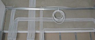
Installation consists of fastening the panels to the frame; there are several types of fasteners and brackets: on slate, on metal, tiles, hidden on the roof sheathing. Support rails, clamps, clamps (end and central) guides are purchased or included in the kit for the selected installation option.
The connecting butt elements create a frame from fixing slats. Terminal elements and conductor holders are also used - they combine aluminum frames and ground them, fixing cables.
If installation is carried out on a roof with a slope, then the optimal angle for panels is 30... 40° in northern latitudes, for example, 45°. In general, for self-cleaning of modules by rain, the angle should be at least 15°.
These positions are created with support profiles, often making a convenient, collapsible, adjustable, rotating structure.
When the array is illuminated unevenly, the panel in a brighter place produces more current, which is partially spent on heating the less loaded solar panels. To eliminate this phenomenon, cut-off diodes are used, soldered between the planes from the inside.
Principle of operation
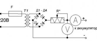
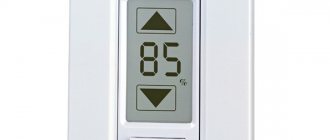
If there is no current from the solar battery, the controller is in sleep mode. It doesn't use a single watt from the battery. After sunlight hits the panel, electric current begins to flow to the controller. It should turn on. However, the indicator LED along with 2 weak transistors turns on only when the current voltage reaches 10 V.
Once this voltage is reached, current will flow through the Schottky diode to the battery. If the voltage rises to 14 V, amplifier U1 will start working, which will open the MOSFET transistor. As a result, the LED will go out and two low-power transistors will close. The battery will not charge. At this time, C2 will be discharged. On average this takes 3 seconds. After capacitor C2 discharges, the hysteresis of U1 will be overcome, the MOSFET will close, and the battery will begin to charge. Charging will continue until the voltage rises to the switching level.
Charging occurs periodically. Moreover, its duration depends on the charging current of the battery and how powerful the devices connected to it are. Charging continues until the voltage reaches 14 V.
The circuit turns on in a very short time. Its activation is influenced by the charging time of C2 with current, which limits transistor Q3. The current cannot be more than 40 mA.
Operating principle of the battery charge controller
Without an intelligent energy distribution system, the generated current will flow to the battery terminals constantly, which will inevitably lead to an increase in voltage. Each battery has its own limit value - this parameter depends on the type of battery design and the ambient temperature.
When the voltage exceeds the recommended level, overcharging will occur, which will lead to a sharp increase in the temperature of the electrolyte. The battery will begin to boil and intensely release distilled water vapor into the air. If you do nothing, the battery life will be halved. In practice, there are cases where storage containers have completely dried out after a while. To avoid this, manufacturers of modular photo panels offer two alternative options:
- measure voltage manually and independently control the process of generation and accumulation of electric current;
- install a controller for solar panels - in this case, the switching device automatically adapts the performance of the solar system to the needs of the consumer.
At night, the battery controller is in “sleep” mode. Once the sun's rays hit the photocells, the generated direct current will flow through the switching device. When the voltage becomes more than 10 V, the electric current will be redirected to the Schottky diode, and then only enter the battery.
If the voltage exceeds 14 V, the amplifier will automatically turn on, which will open the MOSFET - an insulated gate transistor. At this moment the batteries will not be charged. After the capacitor is completely discharged, the MIS transistor will close and the battery will automatically charge. The charging process itself lasts until the voltage rises again to the maximum level.
What controller parameters need to be taken into account
The controller for the solar panel can receive voltage simultaneously from several solar systems, which are connected according to different circuits. In order for the battery charge controller to work correctly, it is extremely important to take into account the total input voltage and current ratings.
It is also advisable to provide a reserve of technical characteristics at the level of 20–25%. What is it for? Firstly, manufacturers often overestimate the actual operating parameters of photocells on solar panels. Secondly, solar radiation is unstable - during abnormal activity, solar energy indicators can easily exceed the permissible design limit.
The formula for approximate calculations is 1.2P ≤ I×U, where:
- P – total power of photopanels;
- I – current at the output of the switching device;
- U – output voltage under load.
It is not advisable to use controllers for solar panels as universal power sources - it is not recommended to connect household electronic devices to them, since by default these modules are designed exclusively for “direct contact” with batteries.
Where should the regulator be installed?
The device is mounted directly between the battery and the active solar system. When using household appliances (washing machine, TV, etc.), it is necessary to add 1-2 inverters to the connection diagram, which are necessary to convert direct current (12 V) into alternating current at 220V. The inverter is connected to the system immediately after the battery.
Additionally, you will need to install a fuse to reliably protect the equipment from overloads and short circuits. If several photo panels are used at once, it is recommended to install automatic fuses between each working unit of the system, starting installation from the solar battery.
Types
On/Off
This type of device is considered the simplest and cheapest. Its only and main task is to turn off the charge supply to the battery when the maximum voltage is reached to prevent overheating.
However, this type has a certain disadvantage, which is that it switches off too early. After reaching the maximum current, you need to maintain the charging process for a couple more hours, and this controller will immediately turn it off.
As a result, the battery charge will be around 70% of the maximum. This has a negative impact on the battery.
PWM
This type is an improved On/Off. The modernization lies in the fact that it has a built-in pulse width modulation (PWM) system. This function allowed the controller, when the maximum voltage was reached, not to turn off the current supply, but to reduce its strength.
Because of this, it became possible to charge the device almost 100%.
MRRT
This type is considered the most advanced at present. The essence of its work is based on the fact that it is able to determine the exact value of the maximum voltage for a given battery. It continuously monitors the current and voltage in the system. Due to the constant acquisition of these parameters, the processor is able to maintain the most optimal current and voltage values, which allows it to create maximum power.
Main functions
When it comes to a mobile device, the controller:
- monitors the charging process. From 0 to 10% the capacity is pre-accumulated, and from 10 to 70 – 80% the filling speed is increased due to direct current. Recharging is slower because the resistance in the circuit is increased;
- regulates drawdowns. When executed
Swelling of the lithium-ion battery.
charging the power source, the controller protects the electrical circuit from short circuits and also protects against voltage surges; - blocks recharge. Each battery is characterized by a maximum voltage limit. In the case of Li-Ion products, this is approximately 4.2 V. When the voltage reaches this mark, the controller turns off the power. If this does not happen, the battery may swell or even explode;
- protects against “deep discharge”. If the cell voltage drops below a critical level (for lithium batteries this is 3 V), the rated capacity will decrease and autonomy will decrease;
- balances. One of the functions of the controller is to ensure that all parts of the electrical circuit are charged evenly. This increases the service life of the battery;
- monitors temperature. In case of overheating or hypothermia, a thermistor is activated, the task of which is to turn off the power going to the battery.
The parameters specific to the controller are set during its manufacture.
Instructions for use
Before studying the instructions for using the controller, you need to remember three parameters that must be observed when operating these electronic devices, these are:
- The input voltage of the device should be 15 - 20% higher than the open circuit voltage of the solar panel.
- For PWM (PWM) devices, the rated current must exceed by 10% the short circuit current in the lines connecting energy sources.
- MPPT - the controller must match the system power, plus 20% of this value.
To successfully operate the device, you must study the operating instructions, which are always included with such electronic devices.
The instruction informs the consumer about the following:
Safety requirements - this section defines the conditions under which operation of the device will not lead to electric shock or other negative consequences to the consumer.
Here are the main ones:
- Before installing and configuring the controller, it is necessary to disconnect the solar panels and batteries from the device using switching devices;
- Prevent water from entering the electronic device;
- The contact connections must be tightly tightened to avoid heating them during operation.
- Technical characteristics of the device - this section allows you to select a device according to the requirements for it in a specific circuit and installation location.
Typically this is:
- Types of adjustments and settings of the device;
- Operating modes of the device;
- The control and display elements of the device are described.
- Methods and place of installation - each controller is mounted in accordance with the requirements of the manufacturer, which allows you to operate the device for a long time and with guaranteed quality.
Information is provided on:
- The location and spatial placement of the device;
- The overall dimensions of utility networks and devices, as well as elements of building structures, are indicated in relation to the mounted device;
- Installation dimensions are given for the mounting locations of the device.
- Methods of inclusion in the system - this section explains to the consumer which terminal and how the connection should be made in order to put the electronic device into operation.
Reported:
- In what sequence should the device be connected to the operating circuit?
- Inadmissible actions and measures when turning on the device are indicated.
- Setting up the device is an important operation on which the operation of the entire solar power plant circuit and its reliability depend.
This section tells you how to:
- What indicators and how do they signal the operating mode of the device and its malfunctions;
- Information is provided on how to configure the desired operating mode of the device by time of day, load conditions and other parameters.
- Types of protection – this section tells you which emergency modes the device is protected from.
Alternatively it could be:
- Protection against short circuit in the line connecting the device to the solar panel;
- Overload protection;
- Protection against short circuit in the line connecting the device to the battery;
- Incorrect connection of solar panels (reverse polarity);
- Incorrect battery connection (reverse polarity);
- Protection against device overheating;
- Protection against high voltage caused by thunderstorms or other atmospheric phenomena.
- Errors and malfunctions - this section explains what to do if for some reason the device does not work correctly, or does not work at all.
The connection is considered: malfunction - possible cause of the malfunction - method of eliminating the malfunction.
- Checking and maintenance – this section provides information on what preventive measures need to be taken to ensure trouble-free operation of the device.
- Warranty - indicates the period during which the device can be repaired at the expense of the device manufacturer, subject to proper operation, in accordance with the operating instructions.
Controller connection methods
Considering the topic of connections, it should immediately be noted: for the installation of each individual device, a characteristic feature is working with a specific series of solar panels.
So, for example, if a controller is used that is designed for a maximum input voltage of 100 volts, a series of solar panels should output a voltage no greater than this value.
Any solar power installation operates according to the rule of balancing the output and input voltages of the first stage. The upper limit of the controller voltage must correspond to the upper limit of the panel voltage
Before connecting the device, you need to decide on the location of its physical installation. According to the rules, the installation location should be chosen in dry, well-ventilated areas. Avoid the presence of flammable materials near the device.
The presence of sources of vibration, heat and humidity in the immediate vicinity of the device is unacceptable. The installation site must be protected from precipitation and direct sunlight.
Connection technology for PWM models
Almost all manufacturers of PWM controllers require that the devices be connected in the exact sequence.
The technique of connecting PWM controllers to peripheral devices is not particularly difficult. Each board is equipped with labeled terminals. Here you simply need to follow the sequence of actions
Peripheral devices must be connected in full accordance with the designations of the contact terminals:
- Connect the battery wires to the battery terminals of the device in accordance with the indicated polarity.
- Switch on the protective fuse directly at the point of contact of the positive wire.
- Attach the conductors coming from the solar panel battery to the controller contacts intended for the solar panel. Observe polarity.
- Connect a test lamp of the appropriate voltage (usually 12/24V) to the load terminals of the device.
The specified sequence must not be violated. For example, connecting solar panels first when the battery is not connected is strictly prohibited. By doing this, the user runs the risk of “burning” the device. This material describes in more detail the assembly diagram of solar panels with a battery.
Also, for PWM series controllers, it is not permissible to connect a voltage inverter to the controller load terminals. The inverter should be connected directly to the battery terminals.
Procedure for connecting MPPT devices
The general physical installation requirements for this type of device do not differ from previous systems. But the technological setup is often somewhat different, since MPPT controllers are often considered more powerful devices.
For controllers designed for high power levels, it is recommended to use large cross-section cables equipped with metal end caps for power circuit connections.
For example, for powerful systems, these requirements are supplemented by the fact that manufacturers recommend using a cable for power connection lines designed for a current density of at least 4 A/mm2. That is, for example, for a controller with a current of 60 A, you need a cable to connect to the battery with a cross-section of at least 20 mm2.
Connecting cables must be equipped with copper lugs, tightly crimped with a special tool. The negative terminals of the solar panel and battery must be equipped with adapters with fuses and switches.
This approach eliminates energy losses and ensures safe operation of the installation.
Block diagram of connecting a powerful MPPT controller: 1 – solar panel; 2 – MPPT controller; 3 – terminal block; 4.5 – fuses; 6 – controller power switch; 7.8 – earth bus
Before connecting solar panels to the device, you should make sure that the voltage at the terminals is equal to or less than the voltage that can be supplied to the controller input.
Connecting peripherals to the MTTP device:
- Switch the panel and battery switches to the “off” position.
- Remove the protective fuses on the panel and battery.
- Connect the battery terminals with a cable to the controller terminals for the battery.
- Connect the terminals of the solar panel with a cable to the controller terminals indicated by the corresponding sign.
- Connect the ground terminal to the ground bus with a cable.
- Install the temperature sensor on the controller according to the instructions.
After these steps, you need to reinsert the previously removed battery fuse and turn the switch to the “on” position. A battery detection signal will appear on the controller screen.
Next, after a short pause (1-2 minutes), replace the previously removed solar panel fuse and turn the panel switch to the “on” position.
The device screen will show the voltage value of the solar panel. This moment indicates the successful launch of the solar energy installation.
Varieties
Today there are several types of charge controllers. Let's look at some of them.
MPPT controller
This abbreviation stands for Maximum Power Point Tracking, that is, monitoring or tracking the point where power is maximum. Such devices are capable of lowering the voltage of the solar battery to the voltage of the battery. In this situation, the current strength in the solar battery decreases, as a result of which the cross-section of the wires can be reduced and the design reduced in cost. Also, using this controller allows you to charge the battery when there is not enough sunlight, for example, in bad weather conditions or in the early morning and evening. It is the most common due to its versatility. Used for serial connection. The MPPT controller has a fairly wide range of settings, which ensures the most efficient charging.
Device characteristics:
- The cost of such devices is high, but it pays off when using solar panels over 1000 W.
- The total input voltage to the controller can reach 200 V, which means that several solar panels can be connected in series to the controller, on average up to 5. In cloudy weather, the total voltage of the series-connected panels remains high, which ensures an uninterrupted supply of electricity.
- This controller can operate with non-standard voltage, for example, 28 V.
- The efficiency of MPPT controllers reaches 98%, which means that almost all solar energy is converted into electrical energy.
- Possibility of connecting batteries of various types, such as lead, lithium iron phosphate and others.
- The maximum charge current is 100 A; at this current value, the maximum power output by the controller can reach 11 kW.
- Basically, all models of MPPT controllers are capable of operating at temperatures from -40 to 60 degrees.
- To start charging the battery, a minimum voltage of 5 V is required.
- Some models have the ability to simultaneously work with a hybrid inverter.
Controllers of this type can be used both in commercial enterprises and in country houses, since there are various models with different indicators. For a country house, an MPPT controller with a maximum power of 3.2 kW and a maximum input voltage of 100 V is suitable. In large volumes, much more powerful controllers are used.
PWM controller
The technology of this device is simpler than MPPT. The principle of operation of such a device is that while the battery voltage is below the limit of 14.4 V, the solar battery is connected to the battery almost directly, and the charge occurs quite quickly; after the value is reached, the controller will lower the battery voltage to 13 .7 V, as a result of which the battery will be fully charged.
Device characteristics:
- Input voltage no more than 140 V.
- Works with 12 and 24 V solar panels.
- The efficiency is almost 100%.
- Ability to work with many different types of batteries.
- The maximum input current reaches 60 A.
- Operating temperature from –25 to 55 ºC.
- Possibility to charge the battery from scratch.
Thus, PWM controllers are used most often when the load is not very large and solar energy is sufficient. Such devices are more suitable for owners of small country houses where low-power solar panels are installed.
The MPPT controller, as mentioned above, is the most popular today because it has high efficiency and is capable of operating even in conditions of lack of sunlight. The MPPT controller is also capable of operating at higher powers, ideal for a large country house. However, when choosing a specific type, you need to take into account the amount of input and output current, as well as the degree of power and voltage ratings.
Installing an MPPT controller in small areas is impractical, since it will not pay for itself. If the total voltage of the solar battery is more than 140 V, then an MPPT controller should be used. PWM controllers are the most affordable, as their price starts from 800 rubles. There are models for 10 thousand, when the cost of an MPPT controller is approximately 25 thousand.
Inverters and BPS
| Model | Specifications | Instructions |
| Prosolar PV Hybrid 3 kW | Russian.English | |
| Communication board for Prosolar PV Hybrid 3 kW | English | |
| Latest firmware update for Prosolar PV Hybrid 3 kW | Version from April 2014 | |
| Prosolar Combi PWM | rus. | |
| Prosolar Combi MPPT | rus. | |
| Studer Innotec | ||
| Xtender | English | English rus. |
| Compact and XP Compact | English | English XPC English C |
| HP Compact | English | |
| A.J. | English | English |
| Schneider Electric | ||
| Conext XW | Announcement Installation Guide Conext Multi-Cluster Power System Planning Guide | |
| EPSolar | ||
| STI-500 | rus. | rus. |
| Samil Power | ||
| Solar River 1100-5200TL | rus. English | |
| Solar River 3400-5200TL-D | English | rus. English |
Homemade controller: features, components
The device is designed to work with only one solar panel, which creates a current of no more than 4 A. The capacity of the battery, the charging of which is controlled by the controller, is 3,000 A*h.
To manufacture the controller, you need to prepare the following elements:
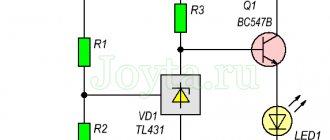
- 2 microcircuits: LM385-2.5 and TLC271 (is an operational amplifier);
- 3 capacitors: C1 and C2 are low-power, have 100n; C3 has a capacity of 1000u, designed for 16 V;
- 1 indicator LED (D1);
- 1 Schottky diode;
- 1 SB540 diode. Instead, you can use any diode, the main thing is that it can withstand the maximum current of the solar battery;
- 3 transistors: BUZ11 (Q1), BC548 (Q2), BC556 (Q3);
- 10 resistors (R1 – 1k5, R2 – 100, R3 – 68k, R4 and R5 – 10k, R6 – 220k, R7 – 100k, R8 – 92k, R9 – 10k, R10 – 92k). They can all be 5%. If you want greater accuracy, you can use 1% resistors.
Where and how is solar energy used?
Flexible panels are used in various fields. Before drawing up a project for powering your home using these solar panels, find out where they are used and what are the features of their use in our climate.
Application area of solar panels
The use of flexible solar panels is very wide. They are successfully used in electronics, building electrification, automobile and aircraft manufacturing, and space facilities.
In construction, such panels are used to provide residential and industrial buildings with electricity.
Portable chargers based on flexible solar cells are available to everyone and are sold everywhere. Large flexible tourist panels for generating electricity in any corner of the globe are very popular among travelers.
A very unusual but practical idea is to use the road surface as a basis for flexible batteries. Special elements are protected from impacts and are not afraid of heavy loads.
This idea has already been implemented. The “solar” road provides energy to the surrounding villages without taking up a single extra meter of land.
Features of the use of flexible amorphous panels
Those who plan to start using flexible solar panels as a source of electricity for their home should know the specifics of their operation.
Solar panels with a flexible metal base are used where increased demands are placed on the wear resistance of mini-power plants:
First of all, users are concerned with the question: what to do in winter, when daylight hours are short and there is not enough electricity to operate all the devices?
Yes, in cloudy weather and short daylight hours, the performance of the panels decreases. It’s good when there is an alternative in the form of the possibility of switching to a centralized power supply. If you don’t have it, you need to stock up on batteries and charge them on days when the weather is favorable.
An interesting feature of solar cells is that when the solar cell heats up, its efficiency decreases significantly.
The number of clear days per year depends on the region. Of course, in the south it is more rational to use flexible batteries, since the sun shines there longer and more often.
Since the Earth changes its position relative to the Sun during the day, it is better to place the panels universally - that is, on the south side at an angle of about 35-40 degrees. This situation will be relevant both in the morning and evening hours, and at noon.
Block diagrams of controllers
Schematic diagrams of PWM and MPPT controllers to consider them with a layman's eye are too complex a point associated with a subtle understanding of electronics. Therefore, it is logical to consider only structural diagrams. This approach is understandable to a wide range of people.
PWM
The voltage from the solar panel travels through two conductors (positive and negative) to the stabilizing element and the separating resistive circuit. Due to this piece of the circuit, potential equalization of the input voltage is obtained and, to some extent, they organize protection of the controller input from exceeding the input voltage limit.
It should be emphasized here: each individual device model has a specific input voltage limit (indicated in the documentation).
This is approximately what the block diagram of devices made on the basis of PWM technologies looks like. For operation as part of small household stations, this circuit approach provides quite sufficient efficiency
Next, the voltage and current are limited to the required value by power transistors. These circuit components are in turn controlled by the controller chip through the driver chip. As a result, the output of a pair of power transistors sets the normal value of voltage and current for the battery.
The circuit also contains a temperature sensor and a driver that controls the power transistor, which regulates the load power (protection against deep discharge of the battery). The temperature sensor monitors the heating status of important elements of the PWM controller.
Usually the temperature level inside the case or on the heatsinks of power transistors. If the temperature goes beyond the limits set in the settings, the device turns off all active power lines.
MPPT
The complexity of the circuit in this case is due to its addition to a number of elements that build the necessary control algorithm more carefully, based on operating conditions.
Voltage and current levels are monitored and compared by comparator circuits, and based on the comparison results, the maximum output power is determined.
- MPPT Controller for Solar Cells
Circuit design in structural form for charge controllers based on MPPT technologies. A more complex algorithm for monitoring and controlling peripheral devices is already noted here.
The main difference between this type of controller and PWM devices is that they are able to adjust the solar energy module to maximum power, regardless of weather conditions.
The circuitry of such devices implements several control methods:
- disturbances and observations;
- increasing conductivity;
- current sweep;
- constant voltage.
And in the final segment of the overall action, an algorithm for comparing all these methods is also used.
Why should you control the charge and how does a solar charge controller work?
Main reasons:
- Will allow the battery to last longer! Overcharging may cause an explosion.
- Each battery operates with a certain voltage. The controller allows you to select the desired U.
The charge controller also disconnects the battery from consumer devices if it is very low. In addition, it disconnects the battery from the solar cell if it is fully charged.
In this way, insurance occurs and the operation of the system becomes safer.
The operating principle is extremely simple. The device helps maintain balance and does not allow tension to drop or rise significantly.
Types of controllers for charging solar batteries
- Homemade.
- MPRT.
- On/Of.
- Hybrids.
- PWM types.
Below we will briefly describe these options for lithium and other battery devices.
DIY controllers
When you have experience and skills in radio electronics, you can make this device yourself. But it is unlikely that such a device will have high efficiency. A homemade device is most likely suitable if your station has low power.
To build this charging device, you will have to find its circuit. But keep in mind that the error should be 0.1.
Here is a simple diagram.
MRRT
Capable of tracking the highest charging power limit. Inside the software there is an algorithm that allows you to monitor voltage and current levels. It finds a certain balance in which the entire installation will operate with maximum efficiency.
The mppt device is considered one of the best and most advanced today. Unlike PMW, it increases system efficiency by 35%. This device is suitable when you have a lot of solar panels.
ONOF type device
It is the simplest one on sale. It doesn't have as many features as others. The device turns off battery charging as soon as the voltage rises to the maximum.
Unfortunately, this type of charge controller for solar panels is unable to charge up to 100%. As soon as the current jumps to the maximum, a shutdown occurs. As a result, an incomplete charge reduces its service life.
Hybrids
The device data is used when there are two types of current sources, for example, the sun and the wind. Their design is based on PWM and MPPT. Its main difference from similar devices is the characteristics of current and voltage.
Its purpose: to equalize the load going to the battery. This happens due to the uneven flow of current from the wind generators. Because of this, the life of energy storage devices can be significantly reduced.
PWM or PWM
The operation is based on pulse width modulation of current. Allows you to solve the problem of incomplete charging. It reduces the current and thereby brings recharging to 100%.
As a result of pwm operation, the battery does not overheat. As a result, this solar control unit is considered very effective.
ON/OFF type controllers
This module performs the function of turning off the batteries from the source under extreme loads. Today, these controllers are used quite rarely and are considered one of the most primitive. The operating principle of the controller is based on constant monitoring of certain values of the generator and the arm of the storage device. The controller turns on when the battery voltage is below the nominal value or is within the voltage parameters. The device turns off if the voltage exceeds the load limit that the controller can withstand. Such controllers are widely used in systems with predictable load, for example, in emergency lighting and alarm systems (HCX-2366 charge-discharge controller).
Types of controllers for solar batteries
In the modern world, there are three types of controllers:
– On-Off;
– PWM;
– MPPT controller;
On-Off is the simplest charging solution; such a controller directly connects the solar panels to the battery when its voltage reaches 14.5 volts. However, this voltage does not indicate that the battery is fully charged. To do this, you need to maintain the current for some time so that the battery gains the energy necessary for a full charge. As a result, you get chronic undercharging of batteries and a reduction in their service life.
PWM controllers maintain the required voltage to charge the battery simply by “cutting off” the excess. Thus, the device is charged regardless of the voltage supplied by the solar battery. The main condition is that it be higher than necessary for charging. For 12 V batteries, the voltage in a fully charged state is 14.5 V, and in a discharged state it is about 11. This type of controller is simpler than MPPT, however, it has lower efficiency. They allow you to fill the battery to 100% of its capacity, which gives a significant advantage over “On-Off” systems.
MPPT controller - has a more complex device that can analyze the operating mode of a solar battery. Its name in full sounds like “Maximum power point tracking”, which in Russian means “Tracking the point of maximum power”. The power a panel produces is highly dependent on the amount of light that falls on it.
The fact is that the PWM controller does not analyze the state of the panels in any way, but only generates the necessary voltages for charging the battery. MPPT monitors it, as well as the currents supplied by the solar panel, and generates output parameters that are optimal for charging storage batteries. Thus, the current in the input circuit is reduced: from the solar panel to the controller, and energy is used more efficiently.
Controller platform
One of the best options is the Arduino platform. There are quite a lot of advantages. The main advantage is accessibility, because the software shell is free. Printed circuit boards are freely available. Thanks to the open architecture of the system, there will be no problems with adding to the line. These controllers support motors with voltages up to 12 volts; you can connect a relay. Arduino also produces other hardware and software. For example, microcontrollers that require 5 volts or 3.3 volts to power them. In addition, programmers have access to special port capabilities (PWM, ADC).
Many improvements can be done yourself. But in 2008, the company split into two parts, which left the same name, but different websites (arduino.cc and arduino.org). When choosing products, you need to pay attention to this, because despite the common past, now Arduino products are different.
What are the different types of controller modules?
Before choosing a charge controller, it is a good idea to understand the basic technical characteristics of the devices. The main difference between popular models of solar battery charge regulators is the method of bypassing the limit voltage limitation. There are also functional characteristics on which the practicality and ease of use of smart electronics directly depends. Let's consider popular and popular types of controllers for modern solar systems.
1) On/Off controllers
The most primitive and unreliable way to distribute energy resources. Its main disadvantage is that the storage capacity is charged to 70–90% of the actual rated capacity. The primary task of On/Off models is to prevent overheating and overcharging of the battery. The controller for the solar battery blocks recharging when the limit value of the voltage supplied “above” is reached. This usually happens at 14.4V.
Such solar controllers use a rather outdated function of automatically turning off the recharging mode when the maximum generated electric current is reached, which does not allow the battery to be charged 100%. Because of this, there is a constant shortage of energy resources, which negatively affects the battery life. Therefore, it is not advisable to use such solar controllers when installing expensive solar systems.
2) PWM controllers (PWM)
Control block circuits operating using the pulse-width modulation method cope with their direct responsibilities much better than On/Off type devices. PWM controllers prevent excessive overheating of the battery in critical situations, increase the ability to accept an electrical charge and control the process of energy exchange within the system. The PWM controller additionally performs a number of other useful functions:
- equipped with a special sensor for recording the electrolyte temperature;
- calculates temperature compensation at different charge voltages;
- supports work with different types of storage tanks for the home (GEL, AGM, liquid acid).
As long as the voltage is below 14.4 V, the battery is connected directly to the solar panel, making the charging process very fast. When the readings exceed the maximum permissible value, the solar controller will automatically lower the voltage to 13.7 V - in this case, the charging process will not be interrupted and the battery will be charged to 100%. The operating temperature of the device ranges from -25℃ to 55℃.
3) MPRT controller
This type of regulator constantly monitors the current and voltage in the system; the operating principle is based on detecting the “maximum power” point. What does this mean in practice? Using an MPPT controller is beneficial because it allows you to get rid of excess voltage from the photocells.
These models of regulators use pulse-width conversions in each individual cycle of the battery recharging process, which allows increasing the output of solar panels. On average, savings are about 10–30%
It is important to remember that the current output from the battery will always be higher than the input current that comes from the photocells
MPRT technology ensures battery charging even in cloudy weather and insufficient solar radiation. It is more expedient to use such controllers in solar systems with a power of 1000 W and higher. The MPPT controller supports work with non-standard voltages (28 V or other values). The efficiency remains at 96–98%, which means that almost all solar resources will be converted into direct electric current. The MPPT controller is considered the best and most reliable option for household solar systems.
4) Hybrid charge controllers
This is the best option if a combined power supply scheme, which consists of a solar power plant and a wind generator, is used as a power plant for a private home. Hybrid devices can operate using MPPT or PWM technology, but the current-voltage characteristics will be different.
Wind generators produce electricity unevenly, which leads to an inconsistent load on the batteries - they operate in the so-called “stress mode”. When a critical load occurs, the hybrid solar controller discharges excess energy using special heating elements that are connected to the system separately.
Controller selection criteria
The battery charging controller for solar panels is a very important element of the power supply system. The varied range of models can make it a little confusing when choosing a device.
It’s easier to choose the right model if you take into account the following criteria when purchasing:
- Input voltage indicator. This value of the selected device should be higher by approximately 20% of the voltage of the batteries that generate converters of sunlight into current.
- Total battery power value. It should not be higher than the output current.
Modern models have a number of additional features designed to increase safety when using charging process regulators. Devices that control charging and discharging processes may be protected from weather conditions, excessive load, short circuits, overheating, and also from incorrect connection (this concerns non-compliance with polarity). Therefore, you should select a device not only depending on the described criteria, but also taking into account the protection functions that will best ensure the safe operation of the device.
Controller requirements.
If solar panels need to provide energy to a large number of consumers, a homemade hybrid battery charge controller will not be a good option - it will still be significantly inferior in reliability to industrial equipment. However, it is possible to assemble a microcircuit for domestic use - its circuitry is simple.
It performs only two tasks:
- prevents batteries from being overcharged, which could lead to an explosion;
- eliminates the complete discharge of batteries, after which it becomes impossible to charge them again.
After reading any review of expensive models, it is easy to see that this is exactly what is hidden behind the big words and advertising slogans. Giving the microcircuit the appropriate functionality yourself is a feasible task; The main thing is to use high-quality parts so that the hybrid battery charge controller from the panels does not burn out during operation.
The following requirements apply to high-quality hand-made equipment:
- it should work according to the formula 1.2P≤UxI, where P is the total power of all photocells, I is the output current, and U is the voltage in the network with empty batteries;
- the maximum U at the input should be equal to the total voltage in all batteries at idle.
When assembling the device with your own hands, you need to read the review of the found option and make sure that its circuit meets these parameters.
Assembling a simple controller.
While a hybrid charge controller allows you to connect multiple voltage sources, a simple charge controller is suitable for systems that only include solar panels. It can be used to power networks with a small number of energy consumers. Its circuit consists of standard electrical elements: switches, capacitors, resistors, a transistor and a comparator for adjustment.
The principle of operation of the device is simple: it determines the charge level of the connected batteries and stops charging when the voltage reaches the maximum value. When it drops, the charging process resumes. Current consumption stops when U reaches a minimum value (11 V) - this prevents the cells from being completely discharged when there is not enough solar energy.
The characteristics of such equipment for solar panels are as follows:
- standard input current U is 13.8 V, can be adjusted;
- battery disconnection occurs when U is less than 11 V;
- charging resumes when the battery voltage is 12.5 V;
- comparator TLC 339 is used;
- at a current of 0.5 A, the voltage drops by no more than 20 mV.
DIY hybrid option.
The advanced hybrid solar controller allows you to use energy around the clock - when there is no sun, direct current comes from the wind generator. The device circuit includes trimming resistors, which are used to adjust the parameters. Switching is carried out using a relay, which is controlled by transistor switches.
Otherwise, the hybrid version is no different from the simple one. The circuit has the same parameters, the principle of its operation is similar. You will have to use more parts, so it is more difficult to assemble; It’s worth reading a review for each element used to make sure of its quality.
Reasons for blocking the battery by the controller
If the controller blocks the battery, the reason may be the following:
- short circuit inside the battery;
- deep discharge – critical voltage drop across the cells.
A discharged battery should be charged as soon as possible. If you store it in this condition, further self-discharge will lead to complete discharge, and it will not be possible to charge the battery. For safety reasons, the controller simply will not allow the charging process to start.
This is explained by the fact that when storing discharged batteries, irreversible degradation processes occur in their structure, lithium crystals are formed, dangerous contact between the poles and the danger of explosion arise. The controller’s task is to prevent such consequences, so it blocks the further use of batteries with a voltage that has fallen below a critical minimum.
The previous VirtusTec blog article is devoted to lithium batteries for forklifts, stackers, and other types of warehouse equipment.
When do you need a controller?
Solar energy is so far limited (at the household level) to the creation of photovoltaic panels of relatively low power. But regardless of the design of the photoelectric converter of solar light into current, this device is equipped with a module called a solar battery charge controller.
Indeed, the solar photosynthesis installation includes a rechargeable battery - a storage device for the energy received from the solar panel. It is this secondary energy source that is primarily served by the controller.
Next, we will understand the structure and operating principles of this device, and also talk about how to connect it.
The need for this device can be reduced to the following points:
- Multi-stage battery charging;
- Adjusting the battery on/off when charging/discharging the device;
- Connecting the battery at maximum charge;
- Connecting charging from photocells in automatic mode.
A battery charge controller for solar devices is important because the performance of all its functions in proper mode greatly increases the service life of the built-in battery.
Conclusions and useful video on the topic
The industry produces devices that are multifaceted in terms of circuit designs. Therefore, it is impossible to give unambiguous recommendations regarding the connection of all installations without exception.
However, the main principle for any type of device remains the same: without connecting the battery to the controller buses, connection to photovoltaic panels is unacceptable. Similar requirements apply for inclusion in a voltage inverter circuit. It should be considered as a separate module connected to the battery via direct contact.