Balancing board for li-ion battery 18650
What is the function of the balancer in lithium batteries? If several cells are connected in series, their voltage adds up to a total sum, and the battery capacity is equal to the lowest of all cells.
To prevent the laziest part from overcharging, it is disconnected from power, allowing the remaining parts to continue charging. The balancer controls the uniformly distributed charge, so it is included in circuits with a series connection of elements. With a parallel connection, there is no need for balancing: there is an even charge distribution. The balancing board is usually included in the general protective housing of the MBS and is called a “balancing cable”.
↑ Device design
Since I am a fan of packing all the parts into the smallest possible case, I came up with the idea of testing the “bourgeois” method of producing cases from Alexey’s textolite (AlexD). :yahoo:
I found the production process somewhat tedious, but the result is impressive. After painting the body looked just like the factory one! But, perhaps, I will use this method only for small cases; after all, the price of PCB is high. Don't mind the special textures on my walls, I'm undergoing renovations!
Why does the charge drop?
All batteries have a certain capacity, stated in Ah. In passenger cars, batteries of 60-80 Ah are most often found. That is, at 60 Ah, the device can produce a current of 1 Ampere for 60 hours. But this is in theory.
In practice, everything is different. As soon as the engine starts, the charge drops significantly. But it is compensated by the operation of the generator. Not all drivers drive a lot and often, and therefore the generator simply does not have time to replenish the entire charge. It has been proven that in most cases, cars are operated with constant undercharging.
Capacity can decrease under the influence of various factors:
- poor fastening, mechanical damage;
- electrical problems;
- violation of the integrity of electrical wiring;
- sulfation processes;
- driving around the city on short trips;
- low ambient temperature, etc.
Since most drivers drive in such conditions, it is imperative to periodically check the condition and charge of the battery.
How to charge a 18650 battery
18650 battery
Well-known charger manufacturers use a two-stage battery charging method.
The two-stage charging method includes:
- The task of the charger at the first stage is reduced to charging with a stabilized current. The charging current is determined by the nominal capacity of the battery with a coefficient of the order of 0.2 to 0.5. During charging, the voltage automatically increases to maintain a stable current. At a voltage of 4.2V, the charging process stops at this stage. By this point, the battery manages to replenish its capacity by 70-80%. In order to reduce charging time, a rapid charging process is used for lithium batteries. In this case, the charging current is taken with a coefficient of 0.5-1.0;
- Charging 18650 in the second stage takes place with a constant voltage. The 18650 charging board supports Ucharge ~ 4.15-4.25V and controls the current value. The current value during charging gradually decreases to a value of 0.05-0.01 of the battery capacity. Accordingly, the charging process is considered complete.
In addition to the above-mentioned charging stages, a preparatory battery charge is applicable for 18650 li-ion batteries. Charging is carried out with a reduced current until the voltage on the battery reaches 2.8V.
Behavior of current and voltage during charging
Despite its indispensability, the two-stage charging system has some disadvantages. Since the voltage on the battery is measured while a large charging current passes through it, depending on the internal resistance of the battery, such measurements may vary. In this regard, the voltage can reach 4.3-4.4V, which has an extremely negative effect on the battery. In practice, it is better to use chargers with current pulses if there are gaps between them. During these intervals, the voltage on the battery is measured. The closer the voltage is to the value of a fully charged battery, the shorter the pulse the charger produces. Accordingly, when the measured voltage reaches 4.15V, the supply of pulses will stop.
Stages of pulse charging AK
Circuit diagram of a simple charger for a car battery
The formula for a normal charge is as simple as 5 kopecks - the basic battery capacity divided by 10. The charging voltage should be a little over 14 volts (we are talking about a standard 12 volt starter battery).
A simple circuit diagram of a car charger consists of three components: power supply, regulator, indicator.
Classic - resistor charger
The power supply is made of two winding “trans” and a diode assembly.
The output voltage is selected by the secondary winding. The rectifier is a diode bridge; a stabilizer is not used in this circuit. The charging current is controlled by a rheostat. Important! No variable resistors, even those with a ceramic core, will withstand such a load.
A wire rheostat is necessary to counteract the main problem with such a circuit - excess power is released in the form of heat. And this happens very intensively.
Of course, the efficiency of such a device tends to zero, and the service life of its components is very low (especially the rheostat). Nevertheless, the scheme exists, and it is quite workable. For emergency charging, if you don’t have ready-made equipment at hand, you can literally assemble it “on your knees.” There are also limitations - a current of more than 5 amperes is the limit for such a circuit. Therefore, you can charge a battery with a capacity of no more than 45 Ah.
DIY charger, details, diagrams - video
Quenching capacitor
The operating principle is shown in the diagram.
Thanks to the reactance of the capacitor included in the primary winding circuit, the charging current can be adjusted. The implementation consists of the same three components - power supply, regulator, indicator (if necessary). The circuit can be configured to charge one type of battery, and then the indicator will not be needed.
The highlight of the charger is the capacitor battery. The peculiarity of circuits with a quenching capacitor is that by adding or decreasing capacitance (simply connecting or removing additional elements) you can regulate the output current. By selecting 4 capacitors for currents of 1A, 2A, 4A and 8A, and switching them with ordinary switches in various combinations, you can adjust the charge current from 1 to 15 A in 1 A steps.
At the same time, there is no parasitic heating (except for the natural one generated by the bridge diodes), the efficiency of the charger is high.
DIY lithium batteries for screwdrivers
We advise owners of high-quality hand tools with nickel-cadmium batteries to switch the device to lithium-ion cells after their service life has expired. If you have the skills to read schematics and solder thin wires, you can make a new lithium battery with your own hands from high-current batteries. It is necessary to strictly follow the step-by-step instructions, both during installation and in the selection of components.
Assembly and testing
The case is selected individually. You can glue it yourself from plastic, or buy something more or less suitable. The locations for the output of LEDs and manual control buttons are determined after fixing the board. If desired, you can make a hole for a trim resistor.
Do not try to immediately take a very small case.
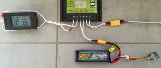
To test the battery charge controller, you will need an adjustable DC\DC converter, which will simulate the voltage at the battery terminals.
The normally open output of the relay is connected to the multimeter in dial mode.
When the battery is charged and the load is connected to it, the multimeter emits a continuous signal, and the blue LED lights up on the controller.
As soon as the voltage drops below the set limit, charging starts. The red LED on the charge controller lights up, and the indication on the multimeter display changes.
That's it, the battery charge controller is ready, you can use it.
You might also like the following materials:
Thank you for reading to the end! Also Don't forget if you liked the article!
Follow us on Twitter:
Share with friends, leave your comments
Add to our group on VK:
ALTER220 Portal about alternative energy
and suggest topics for discussion, together it will be more interesting!!!
Conclusions and useful video on the topic
The desire to make equipment for home use with your own hands is sometimes stronger than the simpler solution - buying an inexpensive device. See what came out of this in the video:
Assessing the prospects for manufacturing electronics on our own, regardless of its purpose, we have to face the idea that the age of “homemade” is coming to an end.
The market is oversaturated with ready-made electronic devices and modular components for almost every household product. Amateur electronics engineers now have only one thing left to do - to assemble home construction kits.
Do you have anything to add, or do you have any questions about assembling and using controllers for a wind generator? You can leave comments, ask questions and add photos of your homemade products - the contact form is in the lower block.
Indication of symbols on the display
- V - measured voltage on battery
- Vs(max) - voltage up to which the charge will be made
- Vmin(m) - minimum voltage on the battery at which the discharge will be turned off
- I - measured charge current
- Is - set charge current
- Id—measured discharge current
- Ii - discharge current set in the menu (discharge current stabilization)
- Imin - minimum current at which the charge will be completed
- H - timer time. For all modes.
- Hi - remaining time before shutdown by timer
- P -capacitance AB-Ah
- LED backlight
1.When the device is connected to the network, display information if the battery is connected
1.1. Voltage to which the charge will be made. Default Vs=14.2 (Selection range in the menu is 1-30 volts.)
1.2.Set charge current. By default Is=0.5A. (selection range in the menu 0.5 -10A. resolution 0.5A.)
1.3. Real voltage on the battery. For example - V=13.7
1.4.Default mode - charging (the mode can be changed in the menu. Names of modes. charge . discharge. kts battery.)
MODE 1.charge
If the battery is not connected, instead of voltage on the battery, display the inscription - no bat. Everything else is the same as when the battery is connected.
Example 1.0. battery not connected
Vs=14.2 Is=0.5A ? Battery Charge
When you press the start button, start the set mode. When pressed again, stop. when the mode is running, the name of the selected mode flashes. When stopped, it lights up constantly.
Example 1.1. battery is connected.
Vs=14.2 Is=0.5AV=13.7 Charge
When the mode is running, instead of the set voltage to which the charge will be made, the real charge current is displayed. Example I = 3.6 A
Example 1.2. charging is in progress.
I=3.6A Is=0.5AV=13.7 charge
After the charging is complete (by a timer or when the set voltage on the battery is reached or the charging current drops to I=min), turn off the charge and remove it - the charge is turned off.
If the charging current exceeds the one set in the menu. And also the voltage on the battery exceeded the one set in the menu - turn off the charge and display the inscription - ERROR.
MODE 2. digit
2. When selecting the discharge mode (when starting this mode, automatically charge the battery to the set voltage and then start discharging.
Example 2.0. Indication in the main mode window. If the mode is not running, the name of the mode (digit) does not blink. When the mode is running, the name of the mode currently used (charge or discharge) flashes.
If the mode is running. AB is not charged. There is an automatic charge, after which the discharge will begin.
I=0.5A charge P=0Ah
2.1 Default discharge current Id = 0.5 A. Selection range in the menu 0.5-10 A. resolution 0.5 A.
2.2. Hi — Time remaining until the end of the discharge, after which the discharge will be disabled by default.
2.3. Measured battery capacity P=????Ah (example P = 45.4Ah). Example 2.1. window during discharge
Id=0.5A Hi=10 P=45.4Ah discharge
After the end of the discharge, give a signal with a pause of 1 second. And so on until another mode is turned on. Apply the signal to pin 4 of the MK. LED out. Display the inscription at the top - P=????Ah. Vm=11.0 at the bottom - OFF digit.
Example 2.2. the discharge is over
P=100.3Ah Vm=11.0 Discharge off
MODE 3. Kts battery. Desulfation.
In the main mode window, if the mode is running, the mode name (KTC) flashes. If it is not running, it does not blink.
3.1. The default charge current is Is = 5A. Range 0.5-10 A
3.2. Discharge current Id = 0.5A. Range 0.5-10 A.
3.3. Voltage on the battery. Frequency 1 Hz.
Example 3.0. desulfation occurs.
I=5.0A Id=0.5A V=14.2 KTTs-AB
After the charging is completed (by a timer or when the set voltage is reached, turn off the mode), display the message - CTC OFF. And the voltage on the battery.
Example 3.1. end of work.
V=14.7 CTC OFF
Discuss the article CAR CHARGER ON CONTROLLER
RoboCraft
A short introduction. 1- Anticipating in advance statements and “advice” such as “why is this needed”, “It’s easier to lay the cable”, “buy ready-made and don’t worry”, I’ll say right away that this whole project is of academic interest rather than economic.
2 - You can read this “opus” “diagonally”, i.e., go directly to the practical parts. Namely, “Converting a UPS into a 220 Volt inverter” and “Independent production of a PWM battery charge controller.” The thing is, I didn't want to ruin the integrity of the story, and I was interested!
Summer. The summer season is in full swing. All sorts of planting and major work have been done, now it’s just barbecue, rest and waiting for the harvest :). And my next attempt to combine business with pleasure. Namely, I wanted to try my hand at organizing the power supply to the second floor of the dacha (as of yet it is not there in principle, only with the help of an extension cord).
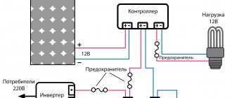
After googling a little and reading the relevant resources, I outlined the “cubes” of the future project. Typical block diagram of the organization of “solar power supply”.
“Large checkered” - it’s simple! It is very convenient that any such cube can be replaced/upgraded in the future. For example, it will be possible to add another battery in parallel. Or install a solar panel if this power is not enough, and so on. In short, I decided to try it.
As they say, “For a big ship, a long voyage,” and “For a serious project, scientific and careful calculation!”