What is a capacitor
A capacitor is an electrical element that is capable of storing a certain electrical charge. The main parameter of the element is the capacitance, which is calculated in farads. 1 farad is quite a large value. Modern capacitors have the following capacitance designations:
- picofarad is denoted pF or pF;
- nanofarad is denoted nF or nF;
- microfarad is denoted mF or mF.
The principle of operation of the device is quite simple. The operation and delivery of a pulse differs only from the current in the circuit to which it is connected.
Capacitor charging process
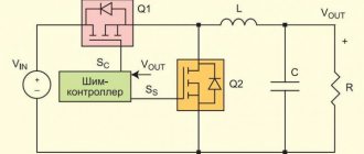
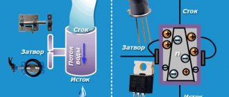
The diagram shows an RC (integrating) circuit powered from a constant power source. When the key is closed to position 1, the capacitor is charged. The current passes through the circuit: “plus” of the source – resistor – capacitor – “minus” of the source.
The voltage on the capacitor plates changes exponentially. The current flowing through the capacitor also changes exponentially. Moreover, these changes are reciprocal; the higher the voltage, the less current flowing through the capacitor. When the voltage on the capacitor is equal to the source voltage, the charging process will stop and the current in the circuit will stop flowing.
Now, if we switch the key to position 2, then the current will flow in the opposite direction, namely through the circuit: capacitor - resistor - “minus” of the source. This will discharge the capacitor. The process will also be exponential.
An important characteristic of this circuit is the product RC, which is also called the time constant τ. During time τ the capacitor is charged or discharged by 63%
In 5 τ, the capacitor gives up or receives the charge completely.
Let's move on from theory to practice. Let's take a 0.47 uF capacitor and a 10 kOhm resistor.
Let's calculate the approximate time for which the capacitor should charge.
Now let's assemble this circuit in multisim and try to simulate
The assembled circuit is powered by a 12 V battery. By changing the position of switch S1, we first charge and then discharge the capacitor through a resistance R = 10 KOhm. To clearly see how the circuit works, watch the video below.
A capacitor is an element capable of storing electrical energy.
The name comes from the Latin word “condensare” - “to thicken”, “to compact”.
The first capacitor was created in 1745 by Pieter van Musschenbroek. In honor of the city of Leiden, in which it was created, the invention was later called the “Leyden jar”.
The capacitor consists of metal electrodes - plates, between which there is a dielectric. Compared to the plates, the dielectric has a small thickness. This determines the capacitor’s ability to accumulate charge: positive and negative charges on its plates hold each other, interacting through a thin non-conducting layer.
Capacitor capacity
depends on:
- plate areas (S);
- distances between them (d);
- dielectric constant of the dielectric material between the plates (ԑ).
They are related to each other by the formula (capacitor formula):
To increase the area of the plates, the plates of some capacitors are made from strips of foil, separated by a strip of dielectric and twisted into a roll. The capacity can also be increased by reducing the thickness of the dielectric between the plates and using materials with a higher dielectric constant. Solid, liquid substances and gases, including air, are placed between the plates of capacitors.
Small capacitors are produced on printed circuit boards by placing two tracks opposite each other.
No matter how high-quality the dielectric in a capacitor is, it still has resistance. Its value is large, but in the charged state of the capacitor there is still a current between the plates. This leads to the phenomenon of “ self-discharge”
": a charged capacitor loses its charge over time.
Characteristics
As an element of an electrical circuit, a capacitor has the following parameters:
- Electric capacitance, which is characterized by the property of accumulating electric charge.
- Rated voltage. The voltage value on the plates at which the element retains its parameters during its service life.
When working with electrical circuits, it is necessary to take into account parasitic parameters that are undesirable:
- Leakage current, which appears due to the imperfection of the dielectric and the quality of the insulation of the plates.
- Series equivalent resistance, which consists of the resistance of the leads, the resistance of the lead-plate contact, and the internal properties of the dielectric.
- Equivalent inductance, which includes the inductance of the leads and plates.
- Dielectric loss tangent, characterizing electrical losses in a capacitor at high frequencies.
- The temperature coefficient of a capacitance, showing how it changes with temperature.
- Parasitic piezoelectric effect, manifested as the generation of voltage during physical impact on the dielectric (shaking, vibration).
Equivalent circuit
CONTENT
The serviceability of electrolytic capacitors is checked by external inspection and leakage resistance measurement.
When checking the appearance of the capacitor, find out:
1) are the values of the nominal capacity and operating voltage, month and year of manufacture indicated;
2) whether the surface of the condenser is dirty, whether it has nicks and dents more than 0.2 mm deep;
3) whether the capacitor terminals are tinned and do not have breaks, cracks or nicks.
After inspecting the capacitor, check the output contact assembly. This is done by applying a small force directed along the axis of the lead to the contact petal or to the wire leads. Stretching the assembly should not cause any damage.
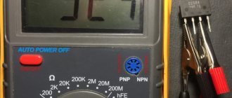
Electrical tests consist of observing the charge of the capacitor on the galvanic cells feeding the ohmmeter and measuring the leakage resistance of the capacitor (see Fig. 1.18).
If the capacitor is in good condition, then the arrow of the device first quickly deflects to the right, reaching the 0 mark of the scale (depending on the capacitance of the capacitor), and then moves relatively slowly to the left and is set above one of the marks on the scale section -> ∞.
If the capacitor has lost its capacity or has a significant leak, then in the first case the instrument needle almost does not deviate to the right, in the second case it deviates to zero or almost to zero, and then sets against the mark located at section 0 of the scale.
The smaller the capacitance of the capacitor, the smaller the angle the arrow deviates to the right at the moment the tester is connected to the capacitor, and the greater the leakage, the more slowly the arrow moves to the left after its return, and, secondly, the further it is set at the end charge from the sign ∞.
A visual representation of the amount of capacitor leakage is given by its recharging current. If you charge a capacitor and then disconnect it from the voltage source, then due to imperfect insulation between the plates, the voltage across the capacitor decreases over time.
To achieve the previous voltage value, it is necessary to recharge the capacitor. The greater the current required to restore the original voltage on the capacitor, the more energy, obviously, the capacitor lost during its self-discharge and, therefore, the greater its leakage current.
Capacitor device
The simplest capacitor consists of two metal plates (plates) separated by a dielectric layer. Capacitance (the ability to accumulate electrical charge) increases with increasing plate area and decreasing thickness of the insulating layer.
The parameters of the simplest design are too small. There are two ways to increase it:
- An increase in the area of the plates, which leads to an increase in dimensions.
- Reducing the thickness of the dielectric, leading to a decrease in the rated operating voltage due to electrical breakdown.
In order to avoid these problems, special designs have been developed. For example, if you make plates of small width and long length, they can be rolled together with a flexible dielectric into a dense cylinder, resulting in a cylindrical capacitor. By placing the dielectric plates alternately, in the form of a layer cake, and alternating connections to the terminals, a rectangular component with a large effective plate area is obtained.
Different types of construction
Another way is to use a thin oxide layer on the surface of a metal foil as a dielectric and a conducting electrolyte solution as a second plate. This produces an electrolytic capacitor whose design has the largest capacity.
Important! Such devices have the disadvantage of maintaining the polarity of the connection, which limits their use: it is only possible in DC circuits as smoothing filters.
AC circuit
In an AC circuit, a capacitor is a resistance. It quickly accumulates a certain charge and gradually releases it. Accumulation and full release occurs during a change in the electric wave.
DC circuit
In a DC circuit, charge accumulates on the plates, increasing the potential difference across the plates. The potential difference increases to the voltage value. As soon as it becomes equal to the voltage, the common circuit is broken.
Types of capacitors
To start powerful compressor engines, oil-filled non-polar capacitors are used.
The housing is filled with oil inside for good heat transfer to the surface of the housing. The body is usually metal or aluminum. The most affordable capacitors of this type are CBB65.
To start less powerful loads, such as fan motors, dry capacitors are used, the housing of which is usually plastic.
The most common capacitors of this type are CBB60, CBB61.
The terminals are double or quadruple for ease of connection.
Capacitor
A capacitor is an electronic component designed to store electrical charge. The ability of a capacitor to accumulate electrical charge depends on its main characteristic - capacitance . The capacitance of a capacitor (C) is defined as the ratio of the amount of electrical charge (Q) to voltage (U).
The capacitance of a capacitor is measured in farads (F), a unit named after the British physicist Michael Faraday. A capacitance of one farad (1F) is equal to the amount of charge of one coulomb (1C) creating a voltage across the capacitor of one volt (1V). Recall that one coulomb (1C) is equal to the amount of charge passing through the conductor in one second (1sec) with a current of one ampere (1A).
However, a pendant is a very large amount of charge relative to how much charge most capacitors can store. For this reason, microfarads (µF or uF), nanofarads (nF) and picofarads (pF) are commonly used to measure capacitance.
- 1nF = 0.000000001 = 10-9 F
- 1pF = 0.000000000001 = 10-12 F
Flat capacitor
There are many types of capacitors with different shapes and internal structures. Let's consider the simplest and most fundamental - a flat capacitor. A flat capacitor consists of two parallel conductor plates (plates), electrically insulated from each other by air or a special dielectric material (for example, paper, glass or mica).
Capacitor charge. Current
In terms of its purpose, a capacitor resembles a battery, but it is still very different in its operating principle, maximum capacity, and charging/discharging speed.
What is capacity
If you remove a single electrical conductor infinitely far, eliminating the influence of charged bodies on each other, then the potential of the remote conductor will become proportional to the charge. But conductors of different sizes do not have the same potential.
The SI unit of capacitance for a capacitor is the farad. The proportionality coefficient is denoted by the letter C - this is the capacitance, which is affected by the size and external structure of the conductor. The material and phase state of the electrode substance do not play a role - the charges are distributed on the surface. Therefore, in the international GHS rules, capacity is measured not in farads, but in centimeters.
A solitary sphere with a radius of 9 million km (1400 Earth radii) contains 1 farad. A separate conductive element holds charges in quantities insufficient for technical use. According to technologies of the 21st century. a capacitance of capacitors with units of measurement higher than 1 farad is created.
A structure of at least 2 electrodes and a separating dielectric is capable of accumulating the amount of electricity required for the operation of electronic circuits. In this design, positive and negative particles are mutually attracted and support themselves. The dielectric between the electron-positron pair does not allow annihilation. This state of charge is called bound.
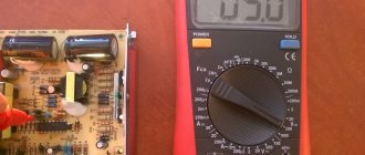
Previously, bulky equipment that was not very accurate was used to measure electrical quantities. Now even a novice radio amateur knows how to measure capacitance with a tester.
Capacitance of the capacitor
Further experiments with the distribution of electricity over the surface of an electrified conductor, carried out by Coulomb and other naturalists, made it possible to establish that a uniform distribution of electricity occurs only on a regular spherical surface.
In general, the charge is uneven and depends on the shape of the conductor, being greater in places of greater curvature. The ratio of the amount of electricity on part of the surface of a conductor to the size of this surface is called the density (thickness) of the electrical layer. It was experimentally established that the electrical density and electrical force are especially high in areas of the surface that have the greatest curvature, especially at the tips. The value characterizing the dependence of the potential of an electrified conductor on its size, shape and environment is called the electrical capacity of the conductor and is designated by the letter C. The electrical capacity of a conductor is measured by the amount of electricity required to increase the potential of this conductor by one:
It will be interesting All about Ohm's law: in simple words with examples for dummies
С = q/ϕ.
The unit of electrical capacity in the SI system is 1 farad (1 F). A farad is the electrical capacitance of a conductor, to which one coulomb of electricity must be supplied to increase its potential by one volt. A ball with a radius of 9·10 6 km would have an electrical capacity equal to 1 F, which is 23 times the distance from the Earth to the Moon. If a conductor is connected to a source of electricity of a certain potential, the conductor will receive an electrical charge depending on the capacitance of the conductor. Its capacity, and, consequently, the amount of electricity with which it is charged, increases if a second conductor connected to the ground is brought closer to it.
A structure consisting of two conductors separated by an insulator, with an electric field between them, all the lines of force of which begin on one conductor and end on the other, was called an electric capacitor. In this case, both conductors are called plates, and the insulating pad is called a dielectric. The process of accumulating charges on the plates of a capacitor is called charging. When charging, charges of equal magnitude and opposite sign accumulate on both plates.
Since the electric field of a charged capacitor is concentrated in the space between its plates, the electrical capacity of the capacitor does not depend on the surrounding bodies. The electrical capacity of a capacitor is measured by the ratio of the amount of electricity on one of the plates to the potential difference between the plates:
C = q/U.
1 F is the electrical capacity of such a capacitor, which can be charged with an amount of electricity equal to 1 C, up to a potential difference between the plates equal to 1 V. For example, the electrical capacitance of a flat capacitor in the SI system is determined by the relation:
С =εε 0 S/ d, where ε is the dielectric constant of the material located between the plates of the capacitor; ε 0 – dielectric constant of vacuum; S is the surface area of the plate (smaller if they are not equal); d – distance between plates.
- Electrical capacity. capacitors
If the plates of a charged capacitor are connected by a conductor, then the charges will move from one plate to another and neutralize each other. This process is called capacitor discharge. Each capacitor is designed for a specific voltage. If the voltage between the plates becomes too high, then discharge can occur directly through the dielectric (without a connecting conductor), i.e. This will result in a breakdown of the dielectric.
It will be interesting What is static electricity and how to get rid of it
A broken capacitor is not suitable for further use. To obtain the electrical capacity of the required value, capacitors are connected into a battery. In practice, there are both parallel and series connections of capacitors.
The structure of a capacitor.
Markings on capacitors
Knowledge of the characteristics of electronic devices is required for accurate and safe operation.
Determining the capacitance of a capacitor involves measuring the value with instruments and reading the markings on the case. The indicated values and those obtained during measurements differ. This is caused by imperfect production technologies and operational variations in parameters (wear, temperature influence).
The body indicates the nominal capacity and parameters of permissible deviations. In household devices, devices with a deviation of up to 20% are used. In the space industry, military equipment and automation of dangerous objects, a spread of characteristics of 5-10% is allowed. Work plans do not contain tolerance values.
The rated capacity is coded according to IEC standards - the International Electrotechnical Commission, which unites national standards organizations in 60 countries.
The IEC standard uses the notation:
- 3 digit encoding. 2 signs at the beginning - the number of pF, the third - the number of zeros, 9 at the end - the value is less than 10 pF, 0 at the front - no more than 1 pF. Code 689 - 6.8 pF, 152 - 1500 pF, 333 - 33000 pF or 33 nF, or 0.033 µF. To make it easier to read, the decimal point in the code is replaced by the letter "R". R8=0.8 pF, 2R5 - 2.5 pF.
- 4 digits in marking. The last one is the number of zeros. The first 3 are the value in pF. 3353 - 335000 pF, 335 nF or 0.335 µF.
- Using letters in code. The letter µ is μF, n is nanofarad, p is pF. 34p5 - 34.5 pF, 1µ5 - 1.5 µF.
- Planer ceramic products are coded with the letters AZ in 2 registers and a number indicating the power of 10. K3 - 2400 pF.
- Electrolytic SMD devices are marked in 2 ways: numbers - the rated capacity in pF and next to it or in the 2nd line if there is space - the value of the rated voltage; a letter encoding the voltage and next to it there are 3 numbers, 2 determine the capacity, and the last one - the number of zeros. A205 means 10 V and 2 µF.
- Surface mount products are marked with a code of letters and numbers: CA7 - 10 µF and 16 V.
- Encodings - by body color.
Calculation using formulas
Calculation of the nominal capacity of an element is required in 2 cases:
- Electronic equipment designers calculate the parameter when creating circuits.
- In the absence of capacitors of suitable power and capacity, craftsmen use element calculations to select from available parts.
RC circuits are calculated using the value of impedance - complex resistance (Z). Ra - current losses due to heating of circuit participants. Ri and Re — take into account the influence of inductance and capacitance of the elements. At the resistor terminals in the RC circuit, the voltage Uр is inversely proportional to Z.
Thermal resistance increases the potential across the load, and reactive resistance decreases. Operating a capacitor at frequencies above resonant frequencies, when the reactive component of the complex resistance increases, leads to voltage losses. The resonance frequency is inversely proportional to the ability to accumulate charge. From the formula for determining Fр, they calculate what values of C (capacitor capacitance) are required for the operation of the circuit.
To calculate pulse circuits, the circuit time constant is used, which determines the effect of RC on the pulse structure. If the circuit resistance and capacitor charging time are known, the capacitance is calculated using the time constant formula. The truth of the result is influenced by the human factor.
Craftsmen use parallel and series connections of capacitors. The calculation formulas are the reverse of the formulas for resistors. A series connection makes the capacitance smaller in the connection of elements; a parallel circuit adds up the values.
Capacitance of a parallel plate capacitor
The capacitance of a solitary conductor is rarely used in practice. In normal situations, guides are not solitary. A charged conductor interacts with surrounding bodies and induces charges on them, and the potential of the field of these induced charges (according to the principle of superposition!) changes the potential of the conductor itself. In this case, it can no longer be argued that the potential of the conductor will be directly proportional to its charge, and the concept of the capacitance of the conductor itself actually loses its meaning.
It is possible, however, to create a system of charged conductors, which, even if a significant charge accumulates on them, almost does not interact with surrounding bodies. Then we can talk about capacitance again - but this time about the capacitance of this system of conductors.
The simplest and most important example of such a system is a parallel-plate capacitor. It consists of two parallel metal plates (called plates) separated by a layer of dielectric. In this case, the distance between the plates is much less than their own dimensions.
First, let's look at an air capacitor with air between the plates.
Let the charges of the plates be equal and . This is exactly what happens in real electrical circuits: the charges of the plates are equal in magnitude and opposite in sign. The quantity - the charge of the positive plate - is called the charge of the capacitor.
Let be the area of each plate. Let's find the field created by the plates in the surrounding space.
Since the dimensions of the plates are large compared to the distance between them, the field of each plate far from its edges can be considered a uniform field of an infinite charged plane:
Difficulties of verification
The process of determining the capacitance of a capacitor directly on the board is complicated by the presence of other circuit components - they distort the readings of the device.
First of all, this applies to elements with low resistance to direct current: fuses, inductors, transformer windings. Determining the capacitance of a capacitor without soldering is possible only in the absence of the mentioned components. Semiconductor devices - diodes and transistors - also have an effect.
When checking a capacitor for breakdown by measuring resistance, the multimeter will display the resistance of the Pn junction instead of infinity (on the display “1”). As a result, the state of the capacitor will remain unknown.
Check Features
The capacitor is checked for serviceability using various methods. The main method is by desoldering it from the circuit. Sometimes you can check the functionality without soldering. But the results of the study will not be accurate - it is influenced by other components. To check the circuit, testers with tiny voltages on the probes are used. Low voltage prevents damage to other components of the board.
Regardless of the features of the models, all electrolytic capacitors have high power. When the test is performed, they are recharged. Its duration is only a few seconds. During the charging process, an increase in the resistance level is observed, with the movement of the tester needle or a change in the digital indicators in the electronic multimeter.
Polar capacitors
These electrolytic conductors are polarized. When connecting to the network, it is necessary to check the correct connection. We connect pluses with pluses, and minuses with minuses. Ignoring this rule leads to an explosion of the electrolyte.
Electrolyte can be solid or liquid. The capacitance of the elements is 0.1–100000 μF. The purpose of the elements is signal alignment and filtering. Marks “-” and “+” are marked on the body. The positive lead is longer. When the polarity is reversed, a breakdown of the dielectric occurs, as a result of which the electrolyte instantly evaporates and the housing ruptures. The dielectric is paper impregnated with electrolyte. Modern buildings are pressed in at the top and cut with a cross.
During an explosion, not the whole thing disintegrates, but only the upper part. Taking into account the specially weakened elements, in the event of a malfunction, swelling of the upper part is visible.
Non-polar capacitors
It is easy to visually distinguish non-polar from polar - it will not have polarity markings on the body. Non-polar ones have a different dielectric material. Consists of ceramics or glass. The self-discharge current is much lower, given the higher dielectric resistance than paper. The higher the resistance of the dielectric partition, the lower the leakage current.
It is not at all necessary to observe polarity when connecting to the circuit. Sometimes such conductors are made very small and included in the circuit in large quantities.
The capacity of the parts is small - from microfarads to picofarads.
How to test a capacitor with a multimeter
The industry produces several types of testing equipment for measuring electrical parameters. Digital ones are more convenient for measurements and give accurate readings. Arrow people prefer the visual movement of arrows.
If the conder appears to be absolutely intact, it is impossible to check it without instruments. It is better to carry out the check by desoldering it from the circuit. This way the indicators are read more accurately. Simple parts rarely fail. Dielectrics are often damaged mechanically. The main characteristic during testing is the passage of only alternating current. The constant passes exclusively at the very beginning for a short period of time. The resistance of the part depends on the existing capacitance.
The prerequisite for testing a polar electrolytic capacitor with a multimeter for performance is a capacity of more than 0.25 μF. Step-by-step verification instructions:
- Discharging the element. To do this, its legs are short-circuited with a metal object. A short circuit is characterized by the appearance of a spark and sound.
- The multimeter switch is set to the resistance value.
- Touch the legs of the capacitor with the probes, taking into account the polarity. Red to the positive leg, black to the negative leg. This is only necessary when working with a polarized device.
The capacitor begins to charge when the probes are connected. Resistance rises to its maximum. If the multimeter beeps when the probes are zero, it means a short circuit has occurred. If the value 1 is immediately displayed on the dial, then there is an internal break in the element. Such conductors are considered faulty - a short circuit and a break inside the element cannot be repaired.
If the value 1 appears after some time, the element is considered normal.
Testing a non-polar capacitor is even easier. On the multimeter we set the measurement to megaohms. After touching the probes, we look at the readings. If they turn out to be less than 2 MΩ, the part is faulty. More than that - serviceable. There is no need to observe polarity.
Electrolytic
As the name suggests, electrolytic conductors in an aluminum case are filled with electrolyte between the plates. The dimensions are very different - from millimeters to tens of decimeters. Technical characteristics can exceed those of non-polar ones by 3 orders of magnitude and reach large values - units of mF.
In electrolytic models, an additional defect appears associated with ESR (equivalent series resistance). This indicator is also abbreviated ESR. Such capacitors in high-frequency circuits filter the carrier signal from parasitic signals. But it is possible to suppress EMI by greatly reducing the level and playing the role of a resistor. This leads to overheating of the part structure.
Rated voltage
The second most important characteristic after capacitance is the maximum rated voltage of the capacitor
. This parameter indicates the maximum voltage that the capacitor can withstand. Exceeding this value leads to “punching” of the insulator between the plates and a short circuit. The rated voltage depends on the insulator material and its thickness (the distance between the plates).
It should be noted that when working with alternating voltage, it is the peak value (the highest instantaneous voltage value per period) that needs to be taken into account. For example, if the effective voltage of the power supply is 50V, then its peak value will be over 70V. Accordingly, it is necessary to use a capacitor with a rated voltage greater than 70V. However, in practice, it is recommended to use a capacitor with a voltage rating of at least twice the maximum possible voltage that will be applied to it.
How to check without desoldering
It is possible to ring the capacitor with a multimeter without desoldering. For such a check, we select a working specimen with similar characteristics and solder it into the circuit parallel to the one being tested. The working device will indicate a problem in the first element. The method is not applicable to high voltage circuits.
You can check a powerful starting capacitor with a multimeter without desoldering for the presence of a spark. The charged conductor is closed with a screwdriver or other tool with an insulated handle. A characteristic sound with a spark will indicate the functionality of the device.
It is not advisable to take measurements without special instruments. It is easy to get an electric shock on high-voltage samples, and the exact values cannot be determined.
First way
The first method is the simplest. The subject is checked by a tester and called with a multimeter. The device is put into resistance testing mode. It is also worth considering polarity. The multimeter probes are connected to the terminals of the capacitor and the resistance is measured. It is worth considering that the obtained value has no practical use, since it may be an indication of another element. In this way, you can check the capacitive part for a short circuit. If the values on the display begin to increase gradually, then the printed part is being charged by the tester and is in good condition.
Second way
The second method requires soldering a capacitor with the same values into the circuit next to the element under test. Soldering must be done in parallel. Both elements are measured on a de-energized board.
Important! Without soldering, you can only test parts that are part of low-voltage circuits. For high-voltage circuits, such testing is prohibited.
Third way
A situation often arises when there are several capacitors on the board, and it is very difficult to determine which one is faulty. Soldering each one is quite labor-intensive; they often fail when heated. In order to check without desoldering, it is necessary to measure the output voltage. It must be the same as indicated on the element body. If there is no voltage, then the part is broken or shorted. If the voltage is less than the optimal value, the element has lost part of its capacity.
Without desoldering, you can determine the faulty element visually. The capacitor may simply burst, have damage on the housing, carbon deposits or swelling.
Visual inspection
Sometimes one glance is enough to identify a faulty capacitor on the board. In such cases, there is no point in checking it with any instruments. The capacitor must be replaced if a visual inspection shows the presence of:
- even slight swelling, traces of leaks;
- mechanical damage, dents;
- cracks, chips (relevant for ceramics).
Capacitors that have any of the above characteristics CANNOT be used.
Device with capacitance measurement function
In the settings panel of such models there is a “CX” sector. The measuring range is smaller than that of an LC meter (up to 200 µF), but it is sufficient for the most common elements.
The check is simple:
- the multimeter switch is set in the “CX” sector to the position with a numerical value that is closest to the expected capacitance;
- the capacitor leads are brought to the contact pads in the “CX” sector or they are touched with probes inserted into sockets with the same mark (depending on the model);
- The display will show the capacity.
Test results
Electrolytic capacitors are polarity sensitive. "CX" sockets and pads are marked with "+" and "-" symbols. The negative terminal of the capacitor is indicated by a tick.
Devices without capacitance measurement function
Such models are used in ohmmeter mode.
Procedure:
- the black probe is plugged into the “COM” socket (negative potential), the red one into the “V/Ω” socket (positive potential);
- the switch is set in the “Ω” sector to the 2 MOhm position;
- Observing polarity, touch the terminals with the probes.
In ohmmeter mode, the multimeter supplies voltage to the probes. It charges the capacitor and the resistance of the latter, gradually increasing from minuscule to a value of over 2 MOhm or infinity (indicated by one on the display).
The increase in resistance is most objectively reflected by an analog (arrow) tester. A malfunction is indicated by the behavior of the device when the resistance:
- immediately became infinite: the conclusion was cut off;
- stopped at below 2 MOhm: the capacitor is broken.
Based on the time during which the resistance increases from minimum to maximum, by comparison with known-good capacitors, you can approximately determine the capacitance of the test item.
This method is not suitable for testing capacitors with low capacitance - 20 µF and below. They charge quickly and even with a working element, the resistance almost immediately becomes infinite.
To test for reversible breakdown, the capacitor is connected to a laboratory DC source with a voltage regulator, and a multimeter in ammeter mode is connected in series with it. The voltage is gradually increased to the maximum permissible. If during this process the tester displays a non-zero current strength, then a reversible breakdown has occurred.
Measuring capacitor resistance with a multimeter
Polar electrolytic capacitors have some features when measuring their internal resistance:
- It is usually at least 100 kOhm. If manufactured well, their leakage resistance can be at least 1 mOhm. As mentioned above, the element being measured must be completely discharged before testing. How this is done is described above.
- When measuring resistance, the measurement limit on the multimeter is set to more than 100 kOhm. After, observing the polarity of connecting the probes, we take measurements. Due to its relatively large capacity, during testing the capacitor will be charged within a short amount of time. The charging process will proceed with a simultaneous increase in resistance, displayed on the display of the device, after which the measured value will stop growing and will have a fixed and final value.
- If the indicator is no more than 100 kOhm , then with a greater degree of probability this is an indicator that the capacitor is working.
When checking with a dial multimeter, everything is done in a similar way:
- The capacitor is prepared (fixed and discharged).
- is set (resistance is not less than the maximum limit).
- A measurement is made, in some cases observing polarity.
- The result is recorded and compared with the operating values.
The peculiarity of measuring resistance using this method is that when it is charged, the parameter itself also grows proportionally and, accordingly, the pointer device indicating the resistance value itself moves from the zero mark to the final fixed one.
It was possible to visually estimate the capacity of the element being measured by the time the needle moved. Thus, the longer the arrow took to reach the final value, the greater the capacitance of the capacitor and vice versa.
The value of the internal resistance of a capacitor is not the main indicator of its performance, so only the capacitance measured with a multimeter can serve as a serious argument.
Determination of capacitor operating voltage
Strictly speaking, if there is no marking on the capacitor and the circuit in which it was installed is not known, then it is IMPOSSIBLE to find out its operating voltage using non-destructive methods.
However, having some experience, you can very roughly estimate the operating voltage based on the dimensions of the capacitor. Naturally, the larger the size of the capacitor and the smaller its capacity, the higher the voltage it is designed for.
Method No. 1: determining operating voltage through breakdown voltage
If there are several identical capacitors and you don’t mind sacrificing one of them, then you can determine the breakdown voltage, which is usually 2-3 times higher than the operating voltage.
The breakdown voltage of a capacitor is measured as follows. The capacitor is connected through a current-limiting resistor to an adjustable voltage source capable of delivering obviously more than the breakdown voltage. The voltage across the capacitor is controlled by a voltmeter.
Then the voltage is gradually increased until breakdown occurs (the moment when the voltage across the capacitor suddenly drops to zero). The operating voltage can be taken to be 2-3 times less than the breakdown voltage. But this is... You can have your own opinion on this matter.
Attention! Be sure to follow all safety precautions! When checking a capacitor for breakdown, it is necessary to use a protected stand, as well as personal eye protection.
The energy of a charged capacitor is enough to cause a small nuclear explosion right on your desktop. And some types of ceramic capacitors, during an electrical breakdown, can shatter into very small but hard fragments that can easily pierce the skin (not to mention the eyes).
Method No. 2: finding the operating voltage of the capacitor through the leakage current
This method of finding out the operating voltage of a capacitor is suitable for aluminum electrolytic capacitors (polar and non-polar). And the majority of such capacitors.
The point is to catch the moment at which its leakage current begins to increase nonlinearly. To do this, we assemble a simple circuit and measure the leakage current at various values of the applied voltage (from 5 volts onwards). The voltage should be increased gradually, in equal portions, recording the readings of the voltmeter and microammeter in the table.
I ended up with a sign like this (my instincts told me that this was a fairly high-voltage capacitor, so I immediately started adding 10V at a time):
| Capacitor voltage, V | Leakage current, µA | Current increase, µA |
| 10 | 1.1 | 1.1 |
| 20 | 2.2 | 1.1 |
| 30 | 3.3 | 1.1 |
| 40 | 4.5 | 1.2 |
| 50 | 5.8 | 1.3 |
| 60 | 7.2 | 1.4 |
| 70 | 8.9 | 1.7 |
| 80 | 11.0 | 2.1 |
| 90 | 13.4 | 2.4 |
| 100 | 16.0 | 2.6 |
As soon as it becomes noticeable that the same increase in voltage each time leads to a disproportionately larger increase in the leakage current, the experiment should be stopped, since we are not faced with the task of bringing the capacitor to an electrical breakdown.
If you build a graph from the obtained values, it will look like this: It can be seen that starting from 50-60 volts, the graph of the leakage current versus voltage acquires a pronounced nonlinearity. And if we take into account the standard range of voltages:
Standard range of rated operating voltages of capacitors, V
| 6.3 | 10 | 16 | 20 | 25 | 32 | 40 | 50 | 63 | 80 | 100 | 125 | 160 | 200 | 250 | 315 | 350 | 400 | 450 | 500 |
We can assume that for a given capacitor the operating voltage is either 50 or 63 V. I agree, the method is quite labor-intensive, but not mentioning it would be a mistake.
Physics laboratory No. 5 - assessing the leakage current of electrolytic capacitors
It all started, as it often happens, with the arrival of a radio amateur friend with the question “Is it true that the parameters of electrolytic capacitors change over time?” After clarifying what specific parameters were meant, we decided that the change in capacitor leakage current associated with time was interesting. More specifically, the task was expressed in the words: “here is a capacitor and, when placed in the cathode bias circuit of the first stage of the amplifier, it adds noise and crackling to the music. Can you find out what's going on in it? Or even watch?
Probably possible, but first
Some starting information
We look at the reference literature. For example, in the “Handbook of Electric Capacitors” edited by I.I. Chetvertkov. and Smirnova V.F. ( Fig. 1 ) and Dammer J.V.A. with Nordenberg G.M. in the book “Capacitors of constant and variable capacity” ( Fig. 2 ) we find places dedicated to leakage current.
Fig.1
Fig.2
In the reference book “Capacitors” by G.A. Goryacheva. and Dobromyslova E.R. It is also said that during the training process the polarity of the supplied voltage should be changed ( Fig. 3 ).
Fig.3
Looking at the publication dates of these sources, we can assume that these recommendations relate to old capacitors made in the last century, and now production technologies are probably different and everything is not so critical as to pay attention to it. But, looking at the reference data for fairly modern aluminum electrolytic capacitors EPCOS ( Fig. 4 ), we also find information about leakage current, storage time, molding (forming) of capacitors (see appendix to the text).
Fig.4
So, there is some information. Now the question is how to design the experiment.
Since this is not a fast matter, you can use the SpectraPLUS program and a sound card with open inputs - this will allow you to measure the DC voltage level for 1 hour and save the data. The test circuit itself consists of 3 resistors and is shown in Figure 5 . The value of resistor R3 was chosen to be excessively large in order to reduce the flowing current and “time-stretch” the processes taking place. The capacitors are connected using alligator clips - firstly, this speeds up the replacement, and secondly, if there is no soldering, then there is no heating of the element under test and there is no need to wait until it cools down.
Fig.5
Before installing the capacitor in the circuit, the output of the power source is set to a forming voltage equal to the voltage indicated on the capacitor body. Then the power source is turned off, the capacitor is clamped with alligator clips and the source is turned on. At this moment, two currents begin to flow through the capacitor - charging and leakage current, and the voltage corresponding to the sum of these currents “drops” across resistor R2. It is fed into the sound card and displayed in the Time Series window of SpectraPLUS as a voltage level that varies over time. The maximum level supplied to the card is determined by the ratio of the resistances of the divider R3/R2 and the selected voltage of the power supply - when set to 16 V, this will be about 0.23 V. After an hour, the power supply is turned off and the data is saved in the form of screenshots of graphs.
It is probably worth clarifying that the main task of the experiment is not to mold the capacitors, but to observe the process itself and find differences in its progress when installing different capacitors (if, of course, these differences exist).
In addition to the capacitor I brought, there were many others at home that were once located in old computer power supplies and motherboards ( Fig. 6 ). They can also be “measured” - all of them have not been energized for more than two or three years, and if the recommendations for mandatory molding after long-term inactivity are considered correct, then using the example of several selected specimens, after applying voltage to the capacitor, we should see changes in the leakage current.
Fig.6
So, yourself
Experiments
I repeat that the time for taking graphs is about 1 hour - this is the “X” scale (about 3600 seconds). The voltage values indicated on the “Y” scale should actually be divided by 10 times - i.e. o corresponds to an input voltage of 150 mV (this should be taken into account if you need to calculate the current flowing through R2).
First, graphs of currents through capacitors for a rated voltage of 16 V were obtained. They are shown in Figure 7 . From top to bottom – 3300×16 green TEAPO, 3300×16 brown Su`scon, 2200×16 black Fuhjyyu, 2200×16 black VENT, 2200×16 black SC (or CS), 1500×16 brown Elite. It can be seen that the appearance of the graphs cannot be strictly tied to the capacitive value of the capacitors being tested - a lot depends on the current and there are specimens with both low leakage current and large ones.
Fig.7
In Figure 8 – capacitor currents for a voltage of 10 V – 3900×10 green TEAPO, 3300×10 black OST IQ, 3300×10 brown LXJ, 2200×10 brown Su`scon. There is also no way to link the type of graphs to the capacity. TEAPO bursts are the result of processes occurring in the capacitor.
Fig.8
Currents through 6.3 V capacitors are shown in Figure 9 (3300×6 blue OST, 2200×6 green TEAPO, 2200×6 brown Nichicon, 1500×6 green SANYO, 1200×6 green CHOYO, 1000×6 blue TEAPO). Bursts in CHOYO are also the result of internal processes and this is exactly the same capacitor that was brought by a radio amateur I know and, one must assume, that it is these processes that cause noise and crackling in the amplifier.
Fig.9
After some time, a K50-35 4700x16 manufactured in 1994 was checked, having lain idle for more than 20 years. The graph turned out to be “not bad” ( Fig. 10 ), and after letting the capacitor stand under voltage for several hours, the result was a graph with a fairly low leakage current ( Fig. 11 ), which can be seen even in the first minute of testing.
Fig.10
Fig.11
Before molding the K50-35 for many hours, the effect of temperature on the leakage current was tested on it - the capacitor was heated with hot air from a soldering hair dryer for 4 minutes. In Figure 12 , this is the section up to the vertical line (with induced noise from the heating element fed through the triac regulator). Then, after the blowing stops, a slight increase in current is visible (most likely associated with internal heating of the capacitor), and then it decreases as the case cools. If we average the graph noise, then the increase in leakage current can be estimated by 3-4 times.
Fig.12
Also, following the recommendations for forming EPCOS capacitors, two measurements were taken with a higher forming current (the resistances of resistors R2 and R3 were reduced to 15 Ohms and 100 Ohms, respectively). The graphs ( Fig. 13 ) turned out to be different in current and similar to the graphs shown above, which indicates the fundamental correctness of the measurements carried out with a low current.
Fig.13
And finally
About noises
While the voltage graphs were being taken, the noise of these voltages was simultaneously analyzed. Since a sound card with a high intrinsic noise and an open input was used, the spectra were not very informative ( Fig. 14 ), but still showed a decrease in noise at low frequencies after an hour of shaping, even if it was not possible to obtain a low leakage current. Dark spectra were taken 2 minutes after voltage was applied, light spectra were taken at the end of an hour of molding.
Fig.14
To make sure that the “activity” of the leakage current can be assessed by the noise level, the spectrum analysis of the K50-35 capacitor was carried out on a less noisy card ( Fig. 15 ). Here the dark spectrum corresponds to the noise of a capacitor that has been molded for an hour, and the light spectrum is the noise after being under voltage for many hours.
Fig.15
About capacity
Before starting the experiments, the capacitances of all capacitors were measured with the RLC-meter program and all readings were close to those indicated on the cases. After the experiments, the measurements were repeated and for most capacitors the capacitance had approximately the same value, and for some it increased noticeably. For example, the K50-35 turned out to be even higher than the nominal - 4740 µF ( Fig. 16 ). The equivalent resistance, of course, is high, but considering that the capacitor is 25 years old, this can be considered normal, i.e. age-appropriate, meaning.
Fig.16
Summarizing
The result is simple - with a more or less responsible approach to the design of radio equipment, one should not neglect the molding (shaping/training) of electrolytic capacitors, as indicated in the technical literature.
You should also probably be more attentive to the equipment if it is new or has been idle for a long time. For example, if the VLF has been lying in the closet or under the table for six months or a year, then you should let it stand on for a while before listening. It is possible that the process of molding capacitors is part of what is called in the audiophile world the words “the device is playing around.”
Andrey Goltsov, r9o-11, Iskitim
Attached files:
- Alyuminievie_elektroliticheskie_kondensatori_EPCOS.rar (7495 Kb)
Tags:
- Spectrum analyzer
How to measure capacitor leakage current?
The method for measuring leakage current has already been described a little higher. I would just like to add that Iut is measured either at the maximum operating voltage of the capacitor or at the voltage at which the capacitor is planned to be used.
You can also calculate the leakage current of a capacitor by an indirect method - through the voltage drop across a previously known resistance. When checking polarized capacitors for leakage, it is necessary to observe the polarity of their connection. Otherwise, incorrect results will be obtained.
When measuring the leakage current of electrolytic capacitors after applying voltage, it is very important to wait some time (5-10 minutes) so that all electrochemical processes are completed. This is especially true for capacitors that have been out of service for a long time.
Testing the capacitor for the quality of contacts in the terminals is carried out as follows
Assemble the circuit shown in Fig. 1.19.
After assembling the circuit, connect conductors P1 and P2 to the radio pickup sockets, set the voltage divider R1 to approximately Urab , and lightly strike the capacitor under test several times with your finger. If the latter is working, then nothing can be heard in the loudspeaker, even if you move the “Volume” knob to the extreme right position. If the contacts in the terminals of the capacitor are bad, then crackling and rustling noises appear in the loudspeaker.
Rice. 1.19. Diagram of a device for testing an electrolytic capacitor for the quality of contacts in the terminals:
Z1 and 32 - terminals connected to a rectifier with a well-smoothed voltage equal to or exceeding the operating voltage ( Uwork of the capacitor under test; R1 - two-watt voltage divider with a resistance of 100 kOhm; V - DC voltmeter, designed to measure a voltage equal to the operating voltage of the capacitor; C1 - the capacitor being tested; R2 - a resistor with a resistance of 100 - 200 kOhm; C2 - a mica ceramic or paper capacitor with a capacity of 5000 pF to 0.1 μF.
Back to the main page … | |
Inspection Precautions
Discharging the capacitor is mandatory. This is especially true for high-voltage parts - they can damage the multimeter or shock a person. Discharge by touching the legs with a metal object or connecting a lamp. The second method makes the discharge process smoother.
During measurement, do not touch the open parts of the probe with your hands - the human body has low resistance and a high leakage rate. In this case, the measurement will be incorrect. The current will follow the path of least resistance and the readings will show a value that has nothing to do with the capacitor.
Measurements on high-voltage capacitors are carried out using rubber gloves and insulated instruments.
A properly functioning electronic component is capable of storing and releasing a certain amount of electricity. Breakdowns during operation are determined not only visually, but also using a multimeter. Testing with a measuring device can clarify the suitability of an element for further use.
Basic capacitor malfunctions
Capacitive elements play a large role in the circuit diagram of any device. Their main function is to charge a certain amount of current and pulse discharge into the circuit. The main malfunctions of capacitors include:
- Normal breakdown. A breakdown can be caused by an increase in operating voltage. Repair requires not only replacing the element, but also determining the cause of the high voltage.
- Internal break. If a radio component breaks, it loses its capacity, since both of its outputs become isolated. A break can occur when the device is dropped or the element itself is poorly assembled.
- A leak. This problem is due to the loss of some capacity. The smaller the permissible and optimal capacity, the smaller the charge size.