Paragraphs 1.7.120 to 1.7.177
Clauses 1.7.1 to 1.7.79 Clauses 1.7.80 to 1.7.119
APPROVED by the Ministry of Energy of the Russian Federation
Order of July 8, 2002 No. 204
Enters into force on January 1, 2003.
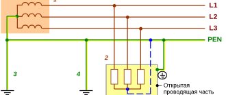
1.7.120. If the building has several separate inputs, the main grounding bus must be made for each input device. If there are built-in transformer substations, the main grounding bus must be installed near each of them. These buses must be connected by a potential equalization conductor, the cross-section of which must be at least half the PE
(
PEN
) - the conductor of that line among the substations extending from the switchboards of low voltage, which has the largest cross-section. Third-party conductive parts may be used to connect multiple main ground bars if they meet the electrical continuity and conductivity requirements of 1.7.122.
Protective conductors ( PE
- conductors)
1.7.121. As RE
-conductors in electrical installations with voltage up to 1
kV
can be used:
1) specially provided conductors:
cores of multi-core cables;
insulated or non-insulated wires in a common sheath with phase wires;
permanently laid insulated or non-insulated conductors;
2) open conductive parts of electrical installations:
aluminum cable sheaths
steel pipes for electrical wiring;
metal shells and supporting structures of busbars and complete prefabricated devices.
Metal boxes and trays of electrical wiring can be used as protective conductors, provided that the design of the boxes and trays provides for such use, as indicated in the manufacturer's documentation, and their location excludes the possibility of mechanical damage;
3) some third party conductive parts:
metal building structures of buildings and structures (trusses, columns, etc.);
reinforcement of reinforced concrete building structures, subject to the requirements of 1.7.122;
metal structures for industrial purposes (crane rails, galleries, platforms, elevator shafts, lifts, elevators, channel frames, etc.).
1.7.122. Use of exposed and third-party conductive parts as PE
- conductors are allowed if they meet the requirements of this chapter for conductivity and continuity of the electrical circuit.
Third party conductive parts can be used as PE
- conductors, if they, in addition, simultaneously meet the following requirements:
1) the continuity of the electrical circuit is ensured either by their design or by appropriate connections protected from mechanical, chemical and other damage;
2) their dismantling is impossible unless measures are taken to maintain the continuity of the circuit and its conductivity.
1.7.123. The following are not allowed to be used as PE conductors:
metal shells of insulating tubes and tubular wires, supporting cables for cable wiring, metal hoses, as well as lead sheaths of wires and cables;
gas supply pipelines and other pipelines of flammable and explosive substances and mixtures, sewerage and central heating pipes;
water pipes with insulating inserts.
.7.124. Neutral protective conductors of circuits are not allowed to be used as neutral protective conductors of electrical equipment powered by other circuits, and also to use open conductive parts of electrical equipment as neutral protective conductors for other electrical equipment, with the exception of shells and supporting structures of busbars and complete factory-made devices that provide the possibility connecting protective conductors to them in the right place.
1.7.125. The use of specially designed protective conductors for other purposes is not permitted.
1.7.126. The smallest cross-sectional areas of protective conductors must comply with table. 1.7.5.
The cross-sectional areas are given for the case when the protective conductors are made of the same material as the phase conductors. The cross-sections of protective conductors made of other materials must be equivalent in conductivity to those given.
Table 1.7.5
Preface
DEVELOPED taking into account the requirements of state standards, building codes and regulations, recommendations of scientific and technical councils for reviewing draft chapters. Draft chapters were reviewed by the working groups of the Coordination Council for the revision of the EMP
PREPARED BY Teploelektroproekt Institute OJSC
agreed in accordance with the established procedure with the Gosstroy of Russia, Gosgortekhnadzor of Russia, RAO UES of Russia (JSC VNIIE)
APPROVED by the Ministry of Energy of Russia, order dated June 20, 2003 N 242
Smallest cross-sections of protective conductors
| Section of phase conductors, mm2 | Minimum cross-section of protective conductors, mm2 |
| S ≤ 16 16 < S ≤ 35 S > 35 | S 16 S /2 |
It is allowed, if necessary, to take the cross-section of the protective conductor less than required if it is calculated according to the formula (only for shutdown time ≤ 5 s
):
where S
— cross-sectional area of the protective conductor,
mm2
;
I
- short circuit current, providing the time to disconnect the damaged circuit by the protective device in accordance with Table.
1.7.1 and 1.7.2 or in a time of no more than 5 s
in accordance with 1.7.79,
A
;
t
— response time of the protective device,
s
;
k
— coefficient, the value of which depends on the material of the protective conductor, its insulation, initial and final temperatures.
The values of k
for protective conductors under various conditions are given in table. 1.7.6-1.7.9.
If the calculation results in a cross section different from that given in table. 1.7.5, then you should select the nearest larger value, and when obtaining a non-standard cross-section, use conductors of the nearest larger standard cross-section.
The maximum temperature values when determining the cross-section of the protective conductor should not exceed the maximum permissible heating temperatures of the conductors during a short circuit
in accordance with Ch. 1.4, and for electrical installations in explosive areas must comply with GOST 22782.0 “Explosion-proof electrical equipment. General technical requirements and test methods".
1.7.127. In all cases, the cross-section of copper protective conductors that are not part of the cable or laid not in a common shell (pipe, box, on the same tray) with phase conductors must be no less than:
2,5 mm2
— with mechanical protection;
4 mm2
- in the absence of mechanical protection.
The cross-section of separately laid protective aluminum conductors must be at least 16 mm2
.
1.7.128. In the TN
To meet the requirements of 1.7.88, it is recommended that neutral protective conductors be laid together or in close proximity to phase conductors.
Table 1.7.6
Calculation of grounding device elements
Determination of the parameters of the conductors used in the design of any ground electrode is carried out taking into account the following considerations:
- The length of the metal rods or pins greatly determines the effectiveness of the entire protective grounding system.
- The length of the elements of metallic bonds is also of great importance.
- The linear dimensions of these structural components determine the material consumption, as well as the total costs of arranging the charger.
- The resistance of vertically driven electrodes is primarily determined by the length.
- Their transverse dimensions do not have a significant impact on the quality and effectiveness of the protection provided.
Please note: The procedure for selecting the cross-section of conductors is determined in the PUE, since this indicator characterizes resistance to corrosion (electrodes should last 5-10 years).
In addition, you should always remember the “golden” rule, according to which the more metal blanks are provided in the circuit, the better the safety characteristics of the circuit.
Installation diagram of a single vertical ground electrode
It should also be taken into account that measures to organize grounding cannot be called an easy task. With a large number of system components, the volume of excavation work increases. And the decision on the specific method to improve the quality of grounding (due to the length or number of electrodes) remains up to the performer himself.
In any case, when arranging a memory of any type, it is recommended to adhere to the following rules:
- the rods must be driven in to a mark at least 50 centimeters below the soil freezing level;
- this arrangement will allow us to take into account seasonal factors and eliminate their influence on the performance of the protective system;
- the distance between the vertically driven elements depends on the shape of the chosen structure and the length of the rods themselves.
To correctly select this indicator, it is recommended to use reference tables.
Table for determining the parameters of grounding electrodes
In order to reduce the volume of upcoming calculations (simplify them), it is first desirable to determine the value of the resistance to the flow of short-circuit currents for a single rod.
Taking into account the influence exerted on the desired value by horizontal structural elements, the resistance for vertical pins is calculated using the following formula:
If the mounted charger is installed in heterogeneous soil (its other name is two-layer), the resistivity can be determined as follows:
where Ψ is the so-called “seasonal” coefficient;
ρ1 and ρ2 – resistivity of soil layers (upper and lower layers, respectively), taken into account in calculations in Ohms per meter;
H – thickness of the soil layer in meters located in the upper part of the earth cover;
t – depth of vertical pins or rods (it corresponds to the depth of the prepared trench), equal to 0.7 meters.
The number of rods sufficient to obtain effective grounding (horizontal components are not taken into account yet) is determined as follows:
where Rн is the spreading resistance standardized by PTEEP.
Taking into account the horizontal elements of the charger, the formula for determining the number of vertical pins takes the following form:
where ηв is understood as the coefficient of utilization of the structure, indicating the mutual influence of the drainage currents of various individual elements on each other.
Additional information: When arranging a system of linearly arranged pins, it should be remembered that in this case their mutual influence is especially strong.
As the installation step of these elements of the protective circuit decreases, its overall resistance to current flow increases noticeably. The number of elements of the grounding structure obtained from the results of the described calculations should be rounded to a larger value.
Online grounding calculations can be automated if you use a special online calculator developed for this on our resource.
The value of the k coefficient for a protective conductor included in a multi-core cable
| Parameter | Insulation material | ||
| Polyvinyl chloride ( PVC ) | Cross-linked polyethylene, ethylene propylene rubber | Butyl rubber | |
| Initial temperature, °C | 70 | 90 | 85 |
| Final temperature, °C | 160 | 250 | 220 |
| k conductor: copper aluminum | 115 76 | 143 94 | 134 89 |
Table 1.7.8
Combined neutral protective and neutral working conductors (PEN conductors)
1.7.131. In multiphase circuits in a TN
for permanently laid cables, the conductors of which have a cross-sectional area of at least 10
mm2
for copper or 16
mm2
for aluminum, the functions of the neutral protective (
PE
) and neutral working (
N
) conductors can be combined in one conductor (
PEN
conductor).
1.7.132. It is not allowed to combine the functions of the neutral protective and neutral working conductors in single-phase and direct current circuits. A separate third conductor must be provided as a neutral protective conductor in such circuits. This requirement does not apply to branches from overhead lines
voltage up to 1
kV
to single-phase electricity consumers.
1.7.133. It is not allowed to use third party conductive parts as the only PEN
- conductor.
This requirement does not preclude the use of exposed and third-party conductive parts as an additional PEN
- conductor when connecting them to the potential equalization system.
1.7.134. Specially provided PEN
-conductors must comply with the requirements of 1.7.126 for the cross-section of protective conductors, as well as the requirements of Ch. 2.1 to the neutral working conductor.
PEN insulation
-conductors must be equivalent to the insulation of phase conductors.
It is not necessary to insulate the PEN
of the busbars of low-voltage complete devices.
1.7.135. When the neutral working and neutral protective conductors are separated starting from any point in the electrical installation, it is not allowed to combine them beyond this point along the distribution of energy. At the point where the PEN
- conductor for the neutral protective and neutral working conductors, it is necessary to provide separate clamps or busbars for the conductors, interconnected.
The PEN
conductor of the supply line must be connected to the terminal or bus of the neutral protective
PE
conductor.
Potential equalization system conductors
1.7.136. Open and third-party conductive parts specified in 1.7.121, or specially laid conductors, or a combination thereof, can be used as conductors of the potential equalization system.
1.7.137. The cross-section of the conductors of the main potential equalization system must be at least half the largest cross-section of the protective conductor of the electrical installation, if the cross-section of the potential equalization conductor does not exceed 25 mm2
for copper or equivalent from other materials.
The use of conductors of larger cross-sections is, as a rule, not required. In any case, the cross-section of the conductors of the main potential equalization system must be no less than: copper - 6 mm2
, aluminum - 16
mm2
, steel - 50
mm2
.
1.7.138. The cross-section of the conductors of the additional potential equalization system must be no less than:
when connecting two open conductive parts - the cross-section of the smaller of the protective conductors connected to these parts;
when connecting an open conductive part and a third-party conductive part - half the cross-section of the protective conductor connected to the open conductive part.
The cross-sections of additional potential equalization conductors that are not part of the cable must comply with the requirements of 1.7.127.
Overhead power lines
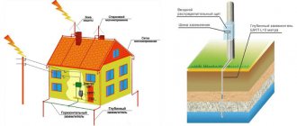
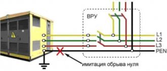
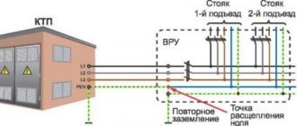
On power line (VL) supports, in accordance with the current provisions of the PUE, re-grounding of the PEN conductor laid from the transformer substation is mandatory. This can be explained by the need to increase the electrical safety of personnel working on overhead lines, as well as the creation of conditions for reliable operation of circuit breakers.
Scheme for re-grounding the neutral wire in the power supply system
Please note: The number and frequency of placement of repeated grounding conductors along the route of power transmission lines is determined by the power supply project prepared for it.
PZ must be established in the following places:
- On supports located at the end of the overhead line.
- On poles, immediately before introducing the “air” onto the object.
- Before any branch from the highway, the length of which is more than 200 meters.
Grounding an overhead line support
To install a grounding device, the underground part of an overhead line support is usually used. If it is not enough to obtain the required characteristics, an additional circuit is made. To design the descent from the top of the pillar, wire without insulation with a diameter of 6.0 or 8.0 mm is used. In addition to the PEN wire, all elements of the support structure made of metal must be grounded. According to the requirements of the PUE, the resistance of the repeat circuit should not exceed 30 Ohms.
On poles with street lighting devices, not only SIP wires are subject to mandatory grounding, but also lamp housings and other metal-based parts of the poles themselves. For these purposes, in urban areas with limited deepening capabilities, horizontal stripes are often used instead of typical vertical pins. After their installation, it is necessary to test the equipped system, checking the real resistance of the grounding device using special measuring tools. Without re-grounding the self-supporting wires and city lighting poles, this section of the route is not allowed for operation by the selection committee.
Portable electrical receivers
1.7.147. The Rules include portable electrical receivers that can be in the hands of a person during their operation (hand-held power tools, portable household electrical appliances, portable radio-electronic equipment, etc.).
1.7.148. Portable AC power receivers should be powered from a mains voltage not exceeding 380/220 V
.
Depending on the category of the room in terms of the level of danger of electric shock to people (see Chapter 1.1), automatic power off, protective electrical separation of circuits, ultra-low voltage, and double insulation can be used to protect against indirect contact in circuits feeding portable electrical receivers.
1.7.149. When using automatic power off, the metal housings of portable power receivers, with the exception of power receivers with double insulation, must be connected to the neutral protective conductor in the TN
or grounded in the
IT
, for which a special protective (
PE
) conductor must be provided, located in the same shell with the phase conductors (the third core of the cable or wire is for single-phase and direct current electrical receivers, the fourth or fifth core is for three-phase current electrical receivers), connected to the body of the electrical receiver and to the protective contact of the plug connector.
The PE
conductor must be copper, flexible, its cross-section must be equal to the cross-section of the phase conductors.
The use of a neutral working ( N
) conductor for this purpose, including one located in a common shell with phase conductors, is not permitted.
1.7.150. It is allowed to use stationary and separate portable protective conductors and potential equalization conductors for portable electrical receivers in testing laboratories and experimental installations, the movement of which is not intended during their operation. In this case, stationary conductors must meet the requirements of 1.7.121-1.7.130, and portable conductors must be copper, flexible and have a cross-section no less than that of phase conductors. When laying such conductors not as part of a cable common with phase conductors, their cross-sections must be no less than those specified in 1.7.127.
1.7.151. For additional protection against direct contact and indirect contact, socket outlets with a rated current of no more than 20 A
outdoor installation, as well as indoor installation, but to which portable electrical receivers can be connected, used outside buildings or in premises with increased danger and especially dangerous ones, must be protected by residual current devices with a rated residual current of no more than 30
mA
.
It is allowed to use hand-held power tools equipped with RCD
plugs.
When using protective electrical separation of circuits in cramped rooms with a conductive floor, walls and ceiling, as well as if there are requirements in the relevant chapters of the Electrical Code in other rooms with special danger, each outlet must be powered from an individual isolation transformer or from its separate winding.
When using ultra-low voltage, power supply of portable electrical receivers with voltages up to 50 V
must be carried out from a safety isolating transformer.
1.7.152. To connect portable electrical receivers to the power supply network, plug connectors should be used that meet the requirements of 1.7.146.
In plug connectors of portable power receivers, extension wires and cables, the conductor on the power source side must be connected to the socket, and on the power receiver side - to the plug.
.7.153. RCD
Protection of socket circuits is recommended to be placed in distribution (group, apartment) panels.
It is allowed to use RCD
sockets.
1.7.154. The protective conductors of portable wires and cables must be marked with yellow-green stripes.
Mobile electrical installations
1.7.155. The requirements for mobile electrical installations do not apply to: ship electrical installations;
electrical equipment located on moving parts of machines, machines and mechanisms;
electrified transport;
RVs.
For testing laboratories, the requirements of other relevant regulations must also be met.
1.7.156. An autonomous mobile power supply source is a source that allows consumers to be powered independently of stationary sources of electricity (power system).
1.7.157. Mobile electrical installations can be powered from stationary or autonomous mobile power sources.
Power supply from a stationary electrical network should, as a rule, be supplied from a source with a solidly grounded neutral using TN-S
or
TN-CS
.
Combining the functions of the neutral protective conductor PE
and the neutral working conductor N in one common conductor
PEN
inside a mobile electrical installation is not allowed.
The separation of the PEN
- supply line conductor into
PE
- and
N
- conductors must be performed at the point where the installation is connected to the power source.
When powered from an autonomous mobile source, its neutral, as a rule, must be isolated.
1.7.158. When powering stationary electrical receivers from autonomous mobile power sources, the neutral mode of the power source and protection measures must correspond to the neutral mode and protection measures taken for stationary electrical receivers.
1.7.159. In the case of powering a mobile electrical installation from a stationary power source, for protection against indirect contact, the power must be automatically turned off in accordance with 1.7.79 using an overcurrent protection device. In this case, the shutdown time given in table. 1.7.1, must be halved or, in addition to the overcurrent protection device, a residual current device must be used that responds to differential current.
In special electrical installations, the use of RCDs
, responding to the potential of the body relative to the ground.
When using RCD
, responding to the chassis potential relative to the ground, the setting for the shutdown voltage value should be equal to 25
V
with a shutdown time of no more than 5
s
.
1.7.160. At the point of connection of the mobile electrical installation to the power source, an overcurrent protection device and an RCD
, responding to differential current, the rated disconnecting differential current of which should be 1-2 steps greater than the corresponding
RCD
installed at the entrance to the mobile electrical installation
If necessary, protective electrical separation of circuits can be used at the entrance to a mobile electrical installation in accordance with 1.7.85. In this case, the isolation transformer, as well as the input protective device, must be placed in an insulating shell.
The device for connecting the power input to a mobile electrical installation must have double insulation.
1.7.161. When applying automatic power shutdown in an IT
To protect against indirect contact, the following must be done:
protective earthing combined with continuous insulation monitoring acting on the signal;
automatic power off, providing a shutdown time in the event of a two-phase short circuit to open conductive parts in accordance with table. 1.7.10.
Table 1.7.10
Grounding and zeroing: what is the difference?
Grounding electrical equipment is possible in two ways:
- Protective grounding: installing a grounding device and connecting a part of an electrical object to it.
- Grounding is the connection of parts of an electrical appliance or installation with a grounded neutral with a neutral wire. This type of protection shuts down the equipment if there is damage.
Grounding conductors are divided into two types: natural and artificial. The first include metal structures of structures that are connected to the ground.
Artificial grounding conductors are steel pins, pipes, and angles screwed into the ground. They have a system of connections between each other using steel strips or wire. The conductors between electrical equipment and grounding conductors are steel or copper busbars. They are connected by welding or bolts.
Protective grounding is required for equipment such as electrical machines, transformers, cabinets.
According to the Rules for the Construction of Electrical Installations (PUE), zeroing, as deliberate protection, is used only in industrial conditions, and should not be practiced in everyday life.
Working with the grounding circuit is designed to prevent short circuits. It is when such a situation occurs that automatic shutdown is triggered. In production, electrical installations have at least a common grounding circuit.
Protective grounding and grounding of electrical installations allows you to protect human life when interacting with electrical objects in the event of problems with their operation.
Electrical installations of animal premises
1.7.170. Electrical installations in livestock buildings should, as a rule, be powered from a 380/220 V
alternating current.
1.7.171. To protect people and animals from indirect contact, automatic power off must be performed using the TN-CS
.
The division of the PEN
conductor into neutral protective (
PE
) and neutral working (
N
) conductors should be done at the input panel.
TN-S
system must be used , and the neutral working conductor must have insulation equivalent to the insulation of the phase conductors along its entire length.
The time of protective automatic power off in premises for keeping animals, as well as in premises connected to them using third-party conductive parts, must comply with table. 1.7.11.
Table 1.7.11