Information from the Rules (PUE 1.7.102.): …….as well as at the overhead line inputs to electrical installations [in which automatic power off is used as a protective measure in case of indirect contact] the PEN conductor must be re-grounded.
Re-grounding of the neutral wire [pen-conductor] of an overhead line at the input to the electrical installation of a country house/building: - It should be noted that if the overhead line is made with non-insulated wires - re-grounding directly on the branch line from the overhead line to the house is not performed - in such cases the neutral wire is grounded only on support.
The QUESTION arises, what about the grounding of the house? ANSWER: If the overhead line wires are not insulated, then the electrical safety conditions when grounding the neutral wire of the electrical network at home cannot be ensured - in such cases, for protection from indirect contact, grounding of open conductive parts is carried out using a ground electrode not connected to the neutral (TT system) with mandatory use of RCDs (see PUE 1.7.59 and in more detail in - TECHNICAL CIRCULAR No. 31/2012 “ON RE-GROUNDING AND AUTOMATIC POWER DISCONNECTION AT THE INPUT OF INDIVIDUAL CONSTRUCTION FACILITIES.”
Theory is one topic, but based on our practice, we can state that the presence of SIP in dacha communities near Moscow and even the presence of cable lines in new, so-called cottage villages is not a reason to thoughtlessly connect the grounding device of an electrical installation without a preliminary assessment of the technical condition of the electrical network country house to the neutral wire of the power source.
What is re-grounding and how to do it correctly?
Re-grounding is an integral part of the overall grounding system.
It is used for grounding the neutral protective conductor of PE and PEN electrical networks up to 1000 Volts in a TN system with a solidly grounded transformer neutral. For re-grounding devices, natural grounding conductors are used. The resistance of natural grounding electrodes is not determined by anything and its value can change at any time, therefore artificial grounding with predetermined parameters is used.
Installation of such a device is necessary to reduce the risk of electric shock to people in close proximity to electrical installations. Repeated grounding is installed at the entrance to the building where the electrical installation is located.
With such a device in emergency situations, the voltage on the housings of electrical installations and electrical appliances is reduced. The potential difference between the ground and the body of the electrical installation is reduced, and a person touching the body of the electrical device becomes protected from electric shock.
Application of TN system
To supply the main part of industrial electrical installations up to 1000 Volts, residential buildings and apartments, the TN system is used. To ensure reliable operation of protection devices and increase electrical safety, it is necessary to ground the neutral wire.
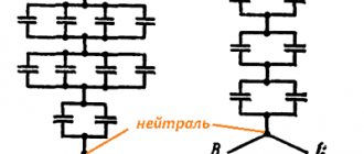
The TN system is divided into the following types:
- TN-C, when the neutral working conductor N is combined with the neutral protective conductor PE.
- TN-S, when the neutral working and neutral protective conductors at the substation are separated.
- TN-CS, when the neutral working and neutral protective conductors at the substation are combined, and when entering the building, the electrical installation is divided into two conductors.
Deaf neutral immersion
Grounding systems are divided into two large groups: with a solidly grounded neutral and with an isolated one.
In the first type of circuit, the neutral conductor (denoted N) is always grounded and can be independent of the protective PE conductor, or can be connected to it to form a PEN conductor. If the neutral wire is combined with a protective conductor, it forms a TN-C system, if carried out separately - a TN-S system, in the case when it is combined at a substation with a protective conductor, and at the entrance to the building it is divided into two conductors - protective PE and functional N , the TN-CS system is formed. Another type is a system in which the neutral conductor is grounded at the substation and three-phase current is supplied to the consumer through four wires, one of which is zero N. This is a TT system.
Application of the TN-C system
The TN-C system was widely used previously with the so-called two-wire network. In this case, there was no grounded contact in the sockets. In networks designed according to this system, the neutral wire was grounded, but if it broke, all devices remained energized. This forced the housing of each individual electrical appliance to be grounded. This system is not designed in modern buildings under construction. Only used in old buildings.
Application of the TN-S system
The TN-S system is more advanced, has a high degree of electrical safety, since it has a separate grounded conductor, but its cost is unreasonably high. With three-phase power, you have to lay five wires from the source - three phases, a neutral and a protective conductor PE.
To eliminate the shortcoming of the TN-S system, TN-CS was created. It provides one conductor PEN, which is a common wire grounded along the entire length from the power source to the entry into the building, and before entry it is divided into a neutral N and a protective conductor PE. This system also has a significant drawback. If the PEN conductor is damaged along the section from the substation to the building, all devices connected inside the building remain under dangerous voltage. For this system, the PUE (Electrical Installation Rules) require measures to provide additional protection for the PEN conductor from mechanical damage.
CT grounding type
The TT system is used to supply electricity outside the city and in rural areas through power lines installed on poles. Connecting electrical installations via this system is permitted only if it is impossible to ensure all electrical safety conditions in the TN system and avoid unjustified material costs. When contacting electrical appliances, protection against current must be carried out by turning off the power in the circuit. For this purpose, the rules prescribe special products - residual current devices - RCDs.
Protective grounding
During the existence of the Soviet electric power industry, many electrical installations, plants, factories were built, and residential and public buildings were electrified.
To power them, a system called TN-C is used, which, in addition to three phases, uses a conductor previously called “ zero ”. Now, according to the new PUE, it is called PEN . It combines the functions of a protective and working conductor.
At transformer distribution substations, at inputs to buildings and at overhead line supports, ground loops .
TN-C grounding system
The main circuit for grounding the PEN conductor is the circuit at the substation, the rest are called “ repeated ”. The requirement for them is milder: if at a transformer substation at a voltage of 380 V the resistance of the grounding loop does not exceed 4 Ohms, then on the supports it is 30 Ohms, and the resistance of the re-grounding loop at the entrance to the building is not standardized.
Important
It is impossible to work in the production shops of enterprises without a grounding loop. It is necessary to connect the housings of all electrical devices with it: distribution boards, electric motors, as well as metal structures that support and mechanically protect cable lines.
To do this, a steel strip is attached along the perimeter of the building along the wall, to which the grounded equipment is connected with the same strips or flexible connections.
This strip is connected to the ground loop, and the zero (and now PEN) bus of the switchgear at the entrance to the building is connected to it.
Ground strip in a building
In fact, it turns out very similar to the TN-S , in which the functions of protective and working conductors are separated. The neutral conductors of the cables supplying electrical equipment are used to conduct working current, and in the event of a short circuit of the phase working conductors to the housing, a steel strip comes into play, diverting life-threatening potential to the ground.
Deaf neutral immersion
Grounding systems are divided into two large groups: with a solidly grounded neutral and with an isolated one.
In the first type of circuit, the neutral conductor (denoted N) is always grounded and can be independent of the protective PE conductor, or can be connected to it to form a PEN conductor. If the neutral wire is combined with a protective conductor, it forms a TN-C system, if carried out separately - a TN-S system, in the case when it is combined at a substation with a protective conductor, and at the entrance to the building it is divided into two conductors - protective PE and functional N , the TN-CS system is formed. Another type is a system in which the neutral conductor is grounded at the substation and three-phase current is supplied to the consumer through four wires, one of which is zero N. This is a TT system.
Application of the TN-C system
The TN-C system was widely used previously with the so-called two-wire network. In this case, there was no grounded contact in the sockets. In networks designed according to this system, the neutral wire was grounded, but if it broke, all devices remained energized. This forced the housing of each individual electrical appliance to be grounded. This system is not designed in modern buildings under construction. Only used in old buildings.
Application of the TN-S system
The TN-S system is more advanced, has a high degree of electrical safety, since it has a separate grounded conductor, but its cost is unreasonably high. With three-phase power, you have to lay five wires from the source - three phases, a neutral and a protective conductor PE.
To eliminate the shortcoming of the TN-S system, TN-CS was created. It provides one conductor PEN, which is a common wire grounded along the entire length from the power source to the entry into the building, and before entry it is divided into a neutral N and a protective conductor PE. This system also has a significant drawback. If the PEN conductor is damaged along the section from the substation to the building, all devices connected inside the building remain under dangerous voltage. For this system, the PUE (Electrical Installation Rules) require measures to provide additional protection for the PEN conductor from mechanical damage.
CT grounding type
The TT system is used to supply electricity outside the city and in rural areas through power lines installed on poles. Connecting electrical installations via this system is permitted only if it is impossible to ensure all electrical safety conditions in the TN system and avoid unjustified material costs. When contacting electrical appliances, protection against current must be carried out by turning off the power in the circuit. For this purpose, the rules prescribe special products - residual current devices - RCDs.
Compatible with shutdown devices
To make a person’s work as safe as possible, the PUE recommends the use of RCDs or automatic devices. Such devices can be used in the TN-CS system, when the PEN wire is divided into PE and N conductors. This separation occurs in the incoming electrical panel on the main grounding bus. Moreover, the connection of the main grounding bus is made to repeated grounding or to a PEN conductor grounded at the entrance to the building.
An RCD or automatic circuit breaker reacts to leakage currents in the load. When a leak occurs in the insulation or when humidity increases, leakage currents appear. When a certain leakage current value is exceeded, the RCD de-energizes the protected circuit. The differential circuit breaker de-energizes the circuit when a short circuit occurs in the load.
The use of a secondary grounding device for the neutral wire affects the operation time of circuit breakers. The lower the grounding resistance, the faster and more reliably the circuit breaker will operate, which means the higher human safety in emergency situations in electrical networks.
Re-grounding of VLI on a concrete support
Repeated grounding is done on a pole or support outside the input device (input device) or VShch (input switchboard), before the input circuit breaker or general switch.
The PEN conductor should be connected to the reinforcement outlet at the top of the reinforced concrete support, both the main one and the braced one (if any). The following photo shows how re-grounding of a PEN-carrying conductor is done using a piercing clamp (4) on a pass-through support, without a tap. Such grounding is done on every third overhead line support and on the support of the outlet to your house.
How to properly connect zero to ground
Incorrect connection of zero to ground can cause tragedy, instead of protection. In a common house input device (IDU), the combined zero must be divided into working and protective conductors. Then the protective zero should be routed to the shields on the floors, and then to the apartments.
This results in a five-wire network:
- 3 phases;
- N;
- P.E.
PE must be connected to the third contact of the sockets. In old houses there is a four-wire network:
- 3 phases;
- combined zero
If the PE conductor is made in the form of an aluminum busbar, then its cross-section must be at least 16 mm², if the copper busbar (brass) is at least 10 mm2. This rule is valid for ASU; otherwise, you should be guided by the table below.
| Section of phase conductors, mm2 | Minimum cross-section of protective conductors, mm2 |
| S≤ 16 | S |
| 16 | 16 |
| S>35 | S/2 |
Circuit breakers and other disconnecting devices cannot be installed on the PE protective conductor; it must be non-switchable. It is necessary to separate the combined PEN zero before the machines and RCDs, after them they should not be connected anywhere!
Forbidden:
- Connect the protective and neutral contacts in the socket with a jumper, because if the zero is broken, dangerous phase voltage will appear on the housings of household appliances;
- connect the neutral and protective conductors with one screw (bolt) on the busbar in the shield;
- PE and N must be connected to different buses, and each wire from each apartment must be screwed with its own screw (bolt). It is necessary to take measures against loosening of bolts and protecting them from corrosion and mechanical damage (clause 1.7.139 of PUE 7).
This connection is used in modern power supply of residential premises or private houses. Which meets the requirements of PEU-7 (clause 7.1.13) for direct and alternating current networks with a voltage of 220/380 volts. After separation, combining them is strictly prohibited.
In a private house, we often receive two or four wires from overhead power lines. Most often there are 2 situations:
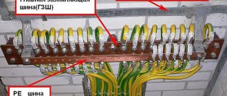
Situation #1 is a good case. Your electrical panel stands on a support, and a re-grounding is driven under it. There are two buses PE and N in the electrical panel. The zero from the support and the wire from the grounding conductor go to the PE bus. There is a jumper between the PE and N buses, from the N bus there is a working zero to the house, from the PE bus there is a protective zero to the house. Buses PE and N can be installed in the house in the distribution board, then the neutral is connected to the ground on one bus in the metering board as in the photo below.
The point is to connect the zero and grounding at the input to all RCDs and automatic circuit breakers, and from this point lead the phase, neutral and ground to the consumers.
Such boards are now often assembled when connecting new private houses to the power grid. In this case, the input circuit breaker is installed in phase, the zero from the overhead power line goes directly to the meter, and the division of the zero (connection to the grounding conductor) is made after it. Less often this is done before the meter, but energy sales are often against such a decision. Why? Nobody knows, they argue about the possibility of electricity theft (the question is how?).
Situation No. 2 - The metering board can be either on a support or in the house or on its facade, it doesn’t matter. You have a sealed input machine and a meter, respectively, you have one or three phases and zero. How to make grounding and is it necessary to connect it to zero? If the overhead power line is new, it is necessary. As in the previous case, you will receive a TN-CS system. Then: the zero from the meter is connected to the PE bus, to which is a wire from the ground electrode (which you will make yourself on your site).
If the overhead power line is old, there is no need to connect the neutral and the ground (Chapter 1.7. PUE clause 1.7.59). Make a TT system (without connecting PE to N). In this case, be sure to use an RCD!
In both situations, each wire on the busbars must be tightened with its own bolt - do not put multiple PE or N conductors under one bolt (or screw).
If you live in an apartment, we recommend reading this article: https://samelectrik.ru/kak-sdelat-bezopasnoe-zazemlenie-v-kvartire.html.
Grounding switches
1.Natural
- water pipes laid in the ground (HW)
- metal building structures and foundations securely connected to the ground
- metal cable sheaths
— casing pipes for artesian wells
— gas pipelines and pipelines with flammable liquids
— aluminum shells of underground cables
— pipes of heating mains and hot water supply
The connection to the natural ground electrode must be in at least two different places.
Artificial
Contour
Remote: group and single
Allows you to choose a place with minimal soil resistance.
Traditionally, for artificial grounding conductors, angle steel with a flange thickness of at least 4 mm, steel strips with a thickness of at least 4 mm, or bar steel with a diameter of 10 mm or more are used.
Recently, deep-seated grounding electrodes with copper-plated or galvanized electrodes have become widespread, which are significantly superior to traditional methods in terms of durability and cost of manufacturing the grounding electrode.
A special problem is the creation of high-quality grounding in permafrost conditions. Here it is worth paying attention to electrolytic grounding systems that can effectively solve the problem.
Detailed information about various sealing schemes, calculation methods and consultations can be obtained on the website www.zandz.ru
Why should ground resistance be measured during installation?
The main indicator of grounding quality is the resistance to current spreading of the ground electrode, which depends on the soil resistivity - the greater the soil resistivity, the more difficult it is to obtain the required result. Work on installing the ground electrode should be carried out with resistance measurements during installation. If you buy a grounding kit with a small total length of electrodes, the depth of the ground electrode may not be enough to achieve the required resistance.
The video shows an example of an intermediate measurement of the resistance of the grounding conductor for the neutral wire [at the input to the electrical installation of a country house] during installation: the depth of the grounding conductor is 6 meters, the spreading resistance is 273 Ohms. This is the answer to the question: should installation continue?
The rules do not prescribe a specific value of the resistance of the charger for re-grounding, but establish the maximum permissible value of resistance to current spreading (30 Ohms) - with adjustments depending on the resistivity of the soil and seasonality, and the lower this value, the better. A grounding device made with the maximum permissible resistance value - for a number of reasons, may not fulfill its function in the electrical installation of a house in the event of emergency situations on the supply line. The best option (if possible) is to re-ground the pen (neutral wire) of the electrical installation of a country house/building with a resistance value of the grounding device close to the resistance of the solidly grounded neutral of the power source, which is several times less than the maximum permissible value for re-grounding specified in the PUE. Installation of such grounding will be more labor-intensive.
Where is re-grounding carried out? 5.18. On an overhead line, grounding must be done with a PEN conductor laid on the same supports as the phase wires. At the ends of overhead lines / or branches from them / with a length of more than 200 m, as well as at the inputs from overhead lines to electrical installations that are subject to grounding, the PEN conductor must be re-grounded. What is recommended to use as grounding conductors? 8.1. It is recommended to use the following as natural grounding conductors and grounding devices: 1-underground or underwater parts of steel and reinforced concrete structures and structures for all purposes, including those with protective waterproofing coatings, in non-aggressive and slightly aggressive environments; 2- reinforced concrete foundations of industrial buildings and structures, including those with protective waterproofing coatings, in non-aggressive, slightly and moderately aggressive environments, provided that the anchor bolts of steel columns (reinforcing bars of reinforced concrete columns) are welded to the reinforcing bars of reinforced concrete foundations; 3-technological, cable and combined (steel and reinforced concrete) overpasses of industrial enterprises; 4- metal pipelines laid in the ground for all purposes, except for pipelines of flammable and explosive substances and mixtures, sewage and central heating; 5- openly laid metal stationary pipelines for all purposes, except for pipelines of flammable and explosive substances and mixtures, sewage and central heating; 6-casing pipes of drilling wells; 7- rails of electrified railways at stations and stages, as well as rails of access roads of temporary current traction substations; 8- rails of main non-electrified railways, as well as rails of access roads, in the presence of a deliberate electrical contact device between the rails of each rail thread; 9- rails of the crane track when installing the crane outdoors, in the presence of a deliberate electrical connection between the rails of each rail thread; 10-grounding switches for overhead line supports, connected to the grounding device of the electrical installation using an overhead line lightning protection cable (if the cable is not isolated from the overhead line supports); 11- repeated grounding switches for overhead lines with voltage up to 1 kV, connected to the grounding device of the electrical installation with a PEN conductor, with the number of overhead lines being at least two; 12 - lead sheaths of cables laid in the ground, with at least two cable lines. Repeated grounding of the PEN conductor in DC networks must be carried out using separate artificial grounding conductors, which should not have metal connections to underground pipelines. Grounding devices on DC overhead lines, designed to protect against lightning surges, are recommended to be used for re-grounding the PEN conductor. Grounding conductors for repeated grounding of the PEN conductor must be selected from the condition of long-term passage of a current of at least 25 A. 5.19. The total resistance to spreading of grounding conductors (including natural ones) of all repeated groundings of the PEN conductor of each overhead line at any time of the year should be no more than 5, 10 and 20 Ohms, respectively, at line voltages of 660, 380 and 220 V of a three-phase current source or 380, 220 and 127 V single-phase current source. In this case, the spreading resistance of the grounding conductor of each of the repeated groundings should be no more than 15, 30 and 60 Ohms, respectively, at the same voltages. If the earth resistivity p is more than 100 Ohm m, it is allowed to increase the specified standards by 0.01 p times, but not more than ten times. 5.20. Hooks and pins of phase conductors installed on reinforced concrete supports, as well as the reinforcement of these supports, must be connected to the PEN conductor. Galvanized steel single-wire grounding conductors must have a diameter of at least 8 mm. Hooks and pins of phase conductors installed on wooden supports, where the PEN conductor is re-grounded, must be grounded.
Main types of supports
Wooden
Such structures in most cases will be made of wood, which will not have bark. The length of one log will be from 5 to 13 meters. The thickness of the support can be from 12 to 26 cm. To make such a wooden support less susceptible to rotting, it will be coated with a special antiseptic. Wooden supports can have two types, which include C1 and C2.
Reinforced concrete
Such devices today are made of reinforcement and concrete. They may resemble the appearance of a rectangle or trapezoid. This reinforced concrete device will also be marked with the name CB. After these letters there will also be numbers written that indicate the length of the pillar. For example, you may come across the marking CB-95 and this means that the reinforced concrete pole will have a length of 9.5 meters. In the photo below you can see what a reinforced concrete support looks like:
The following designs can be found on the modern market:
- C.B.
- C.B.
- C.B.
- C.B.
To perform secondary grounding of the PEN conductor, reinforcement is welded on both sides of the pole.
Do-it-yourself grounding schemes for private houses: 380 V and 220 V
When installing grounding loops, there is no significant difference between the 3-phase (380 volt) and single-phase (220 volt) circuit of a private house. But it is present in the cable routing. Let's figure out what it is.
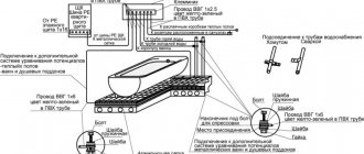
Proper entry into the house. This is how it should look ideally
With a single-phase network, a three-core cable (phase, neutral and ground) is used to power electrical appliances. A three-phase network requires a five-core electrical wire (the same ground and neutral, but three phases)
Particular attention should be paid to the connection - the grounding should not come into contact with zero
Let's consider the situation. 4 wires (zero and 3 phases) come from the substation, connected to the distribution board. Having arranged the correct grounding on the site, we insert it into the shield and “plant” it on a separate bus. The phase and neutral conductors pass through the entire automatic device (RCD), after which they go to electrical appliances. From the grounding bus, the conductor goes directly to sockets and equipment. If the zero contact is grounded, the residual current devices will trip for no reason, and such installation of electrical wiring in the house is completely useless.
The do-it-yourself grounding scheme at the dacha is not complicated, but it requires a careful and careful approach when performing it. It’s easy to do it for only one boiler or other electrical appliance. We will definitely dwell on this below.
The body of a gas boiler, like metal pipes, requires high-quality grounding to avoid sparks.
What is a ground loop in a private house: definition and design
A grounding loop is a structure of pins and busbars located in the ground that provides current drainage if necessary. However, not any soil is suitable for installing a ground electrode. Peat, loam or clay soil are considered suitable for this, but stone or rock are not suitable.
The circuit is ready. All that remains is to lay the tire to the wall of the house
The grounding loop is located at a distance of 1÷10 m from the building. To do this, dig a trench ending in a triangle. The optimal dimensions are side lengths of 3 m. Electrode pins are driven into the corners of the equilateral triangle and connected by a steel bar or angle by welding. From the top of the triangle the tire goes to the house. We will look at the algorithm of actions in detail in the step-by-step instructions below.
Having figured out what the grounding loop is, you can move on to calculating the material and dimensions.
Grounding calculation for a private house: formulas and examples
Electrical installation rules (PUE) and GOST establish the exact framework for how many ohms the grounding should be. For 220 V it is 8 ohms, for 380 it is 4 ohms. But do not forget that for the overall result, the resistance of the soil in which the grounding loop is installed is also taken into account. This information can be found in the table.
| Type of soil | Maximum resistance, Ohm | Minimum resistance, Ohm |
| Alumina | 65 | 55 |
| Humus | 55 | 45 |
| Loess deposits | 25 | 15 |
| Sandstone, groundwater depth deeper than 5 m | 1000 | – |
| Sandstone, groundwater no deeper than 5 m | 500 | – |
| Sandy clay soil | 160 | 140 |
| Loam | 65 | 55 |
| peat bog | 25 | 15 |
| Chernozem | 55 | 45 |
Knowing the data, you can use the formula:
Formula for calculating rod resistance
Where:
- Ro – rod resistance, Ohm;
- L – electrode length, m;
- d – electrode diameter, m;
- T – distance from the middle of the electrode to the surface, m;
- Req – soil resistance, Ohm;
- T – distance from the top of the rod to the surface, m;
- ln – distance between pins, m.
But this formula is difficult to use. For simplicity, we suggest using an online calculator, in which you only need to enter data in the appropriate fields and click the calculate button. This will eliminate the possibility of errors in calculations.
To calculate the number of pins we use the formula
Formula for calculating the number of rods in a contour
where Rn is the standardized resistance for the grounding device, and ψ is the climatic coefficient of soil resistance. In Russia they take it as 1.7.
Let's consider an example of grounding for a private house located on black soil. If the circuit is made of a steel pipe, 160 cm long and 32 cm in diameter. Substituting the data in the formula, we get no = 25.63 x 1.7/4 = 10.89. Rounding the result up, we get the required number of grounding conductors – 11.
Information
This site has been created for informational purposes only. The resource materials are for reference only.
When quoting site materials, an active hyperlink to l220.ru is required.
A document defining the rules of the device, regulating the principles of construction and requirements for both individual systems and their elements, units and communications of the power plant, conditions of placement and installation.
PTEEP
Requirements and responsibilities of consumers, responsibility for implementation, requirements for personnel operating the power plant, management, repair, modernization, commissioning of the power plant, personnel training.
Rules and requirements for the ground loop
In order for the ground loop to work effectively, it must comply with certain rules:
- The external contour should be located at a distance of at least 1 m and no more than 10 m from the house. The optimal distance is 2-4 m from the foundation.
- The depth of the electrodes is selected within 2-3 m. A part of the pin 20-25 cm long is left on the surface for connection with a strip.
- A bus with a cross-section of at least 16 square meters is laid from the input panel to the circuit. mm.
- The connection of the electrodes to each other is ensured only by welding. The connection in the panel can be made with bolts.
- The total system resistance should not exceed 4 ohms for 380 V and 8 ohms for 220 V.
The external ground loop is located in the ground, which implies increased requirements for its design. It should be located below the soil freezing level, because heaving of the soil will push the electrodes out. During operation, corrosion should not destroy the metal and excessively increase its electrical resistance. The strength of the rods should allow them to be driven into hard ground.
Consequences of a zero break
The consequences of a neutral conductor break can be completely different. It all depends on in which network the zero-outage occurred: three-phase or single-phase. Let's consider both cases separately from each other.
- Three-phase network. Burnout or breakage of the neutral conductor in a three-phase network can lead to a complete imbalance of the supply phases, as a result of which an increased voltage of 380 V may occur on one line of the electrical wiring supplying household appliances and lighting devices, and on the other it may drop to zero value. Overvoltage, as well as a decrease in the voltage of the electrical network, is dangerous for any electrical appliances and electronic devices. Extreme voltage levels in electrical wiring can cause fire of both the wires themselves and electrical appliances, which will lead to a fire in the room.
- Single-phase network. A completely different picture arises when the “zero” is broken in a single-phase network, which is supplied to apartments and houses from the distribution board. Each power line of a group of lighting devices and household appliances consists of two conductors: “zero” and phase. In addition, in most modern multi-storey buildings, the electrical wiring cable has a third core for connecting protective grounding to electrical appliances, which is not the case in older buildings. When the “zero” in a single-phase network breaks, a dangerous voltage of 220 V appears on the neutral wire.
As we can see, if the neutral wire breaks in any network, both three-phase and single-phase, a number of negative and dangerous consequences can arise. What to do to prevent such a development of events? Of course there is a way out! Protection against burning out of the “zero” or its breakage is necessary! Below we will consider all types of protection against breakage or burnout of the “zero” in three-phase and single-phase networks.