The safe operation of electrical equipment both at home and in an industrial enterprise directly depends on the quality of the supplied supply voltage. The issue of network instability can be solved quite simply by using a stabilizer. Its correct choice becomes a necessary condition for the operation of the device to be correct, reliable and efficient. But a situation is possible when the voltage stabilizer turns off, and the equipment remains unprotected, and the device itself is subject to increased wear.
Why do you need a voltage stabilizer?
The voltage stabilizer serves to equalize the input voltage. Also, the stabilizer serves as protection against short circuits and power overloads. In simple words, if you have bad voltage at home, it is low or fluctuates a lot, then you need a stabilizer.
Today, there are various voltage stabilizers: relay, servo, triac, and others. We will not consider their design in detail, since this is the topic of more than one article.
It’s better to consider why the voltage stabilizer turns off, because this is one of the most common problems when operating this equipment.
Why does the voltage stabilizer keep turning off?
It happens that after purchasing and installing a voltage stabilizer, it begins to turn off and goes into a delay. The stabilizer delay is a certain time, usually 5-6 seconds, during which the automation checks the incoming voltage, after which it commands the stabilizer to turn on.
So, frequent shutdowns of the voltage stabilizer are most often associated with:
- With insufficient power input voltage, the voltage is very low;
- With weak voltage stabilizer power;
- Due to a short circuit in the electrical network;
- Due to high inrush currents;
- Due to overheating of the stabilizer.
Let's look at each of the above problems in order to understand what to do if the voltage stabilizer turns off.
Exceeding the permissible current
It would seem that when purchasing almost any electrical equipment, one of the most important parameters is its power. And yet, users manage to choose the wrong model due to a negligent attitude to this issue. The voltage stabilizer becomes the power source for your equipment, so the choice of its power and other characteristics should be approached as seriously as possible. If the voltage stabilizer constantly turns off, it is possible that the current protection is triggered. Modern stabilizers usually have two levels of protection. If the current is slightly exceeded, electronic protection is triggered after a certain time. The beating of the machine, in turn, often indicates an avalanche-like current surge, which is typical for short circuits.
Why does the voltage regulator constantly click and turn off?
Service centers often encounter customer requests due to the fact that the voltage stabilizer constantly turns off.
Consumers almost always believe that this is a consequence of a malfunction of the stabilizer, when the reality turns out to be much more prosaic. We will try to consider common reasons for the malfunction of the device and come to one logical conclusion. It would seem that when purchasing almost any electrical equipment, one of the most important parameters is its power. And yet, users manage to choose the wrong model due to a negligent attitude to this issue.
The voltage stabilizer becomes the power source for your equipment, so the choice of its power and other characteristics should be approached as seriously as possible. If the voltage stabilizer constantly turns off, it is possible that the current protection is triggered. Modern stabilizers usually have two levels of protection.
If the current is slightly exceeded, electronic protection is triggered after a certain time. The beating of the machine, in turn, often indicates an avalanche-like current surge, which is typical for short circuits.
Most household voltage stabilizers (servo drive, relay step and electronic step) carry out adjustment based on the principle of changing the transformation ratio of the autotransformer. The main advantage of this approach is the low cost and reliability of the design.
However, there is one drawback that many people forget to take into account when choosing a suitable model: when the input voltage decreases, the permissible output power decreases. The greater the drawdowns the stabilizer needs to compensate for, the lower its power.
Therefore, we recommend choosing a stabilizer with more than a 30% power reserve.
Starting currents
Many consumers forget to take into account the starting currents of some types of household appliances. In particular, the refrigerator compressor is constantly running in a cyclic mode. Each start-up is accompanied by high starting currents, several times higher than the current in operating mode. The voltage stabilizer must either have a power reserve sufficient to handle inrush currents, or an overload capacity. Of course, it is much safer to rely on power reserves.
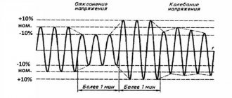
A common reason for the voltage stabilizer to turn off is when the input voltage goes beyond the operating stabilization range. Let's consider this issue in more detail. Any stabilizer is designed to compensate for network fluctuations with a certain amplitude. The device cannot operate if the input voltage is too high or too low. If the stabilizer does not hold voltage and then turns off completely, there is no need to rush to take the device for repair.
The answer may be quite simple: the voltage stabilizer is simply not designed for the amplitude of network fluctuations that are typical for your network. If the voltage stabilizer constantly clicks (in the case of a relay type model), then the network is very unstable and there may well be surges and sags that the device simply cannot cope with.
Moreover, the shutdown may be due to either exceeding the operating stabilization range or due to insufficient power reserve when compensating for deep drawdowns.
What conclusion do the main reasons for the constant shutdown of the voltage stabilizer lead to? The reason lies not in the stabilizer itself, but in its incorrect choice. The device simply cannot operate in conditions for which it was not intended. That's why we always focus on careful selection based on specific needs.
To buy a stabilizer and forget about any problems, follow a number of rules:
- Study the main types of voltage stabilizers and, based on their advantages and disadvantages, decide in favor of one of them.
- Calculate the power of the equipment that needs to be protected. Always take the maximum values, even taking into account the starting currents of some consumers. Accurate calculation is very important. Selecting a stabilizer that is too powerful does not pose any danger - you get the device with a reserve - but you will have to overpay for it. It is much worse to choose a stabilizer with low power, which will lead to protective shutdowns.
- The wider the stabilization operating range, the better. It will be helpful if you know approximately what voltage drops occur directly in your network in order to select a model with the ideal operating range.
- If you have no desire or opportunity to study the equipment, you should not make rash decisions - consult with specialists. For example, managers of the Voltmarket online store are ready to advise you on all issues and provide support at all stages of purchasing a stabilizer, right up to installation and connection.
Of course, there are cases when a shutdown occurs due to a malfunction. If the voltage stabilizer keeps turning off, try to find out the reason. The diagnostic capabilities of the device will help with this. Most often, the display, if available, displays an error code that can be used to determine the malfunction.
Do you want me to be Vanga for a little while? Even without knowing the model of your clicking friend, I can say with confidence that it is assembled using a relay circuit. You ask, how do I know this? Yes, because only relays can click in stabilizers.
To understand what is happening, let's look at how almost every stabilizer works.
All of them are assembled using an autotransformer circuit (well, except for double conversion stabilizers, but we won’t touch them for now). An autotransformer is a thing that, depending on the ratio of winding turns, can either increase or decrease the voltage.
If the voltage in the network becomes slightly higher than necessary, the stabilizer circuit switches to a lower-voltage winding of the autotransformer and, thus, the voltage at the output of the stabilizer decreases.
And vice versa, if the voltage in the socket drops below a certain threshold, the stabilizer switches to the step-up winding of the transformer.
The switching of the autotransformer windings is controlled by the stabilizer controller. And the switching itself is carried out using a set of relays (indicated in the diagram as Q1-Q7). It is the relays that produce those very clicking sounds that we hear at the moment of switching.
Usually there are from 4 to 7 relyushkas inside the stabilizer. Here's what they look like in real life:
[/su_box]
Now it’s clear why the voltage stabilizer clicks? And the more often the voltage in your outlet jumps, the more often the stabilizer will switch. It also happens that at the moment of clicks, the light blinks or some power-sensitive equipment (for example, a computer or air conditioner) turns off.
There may be several reasons. Let's list the most likely ones (in order of decreasing probability):
- One of the relays is faulty. Relays have a limited switching resource. Then their contacts begin to burn, and the contact resistance increases greatly. This leads to a strong drop in the output voltage, especially when connecting a powerful load. The voltage sags, the stabilizer controller notices this and tries to correct the situation by switching to the next stage. After switching, it turns out that the voltage is too high and it plays everything back. The result is an endless cycle of switching back and forth.
- Disgusting condition of the power supply network (large number of twists, poor contacts, long line length with insufficient conductor cross-section). When you try to connect the load through a stabilizer, the voltage in the network drops at the moment of switching. The stabilizer detects this fact and tries to increase it by switching to a higher voltage winding of the autotransformer. But at the moment of switching, the load power circuit is momentarily interrupted, and the voltage in the network jumps to its normal level. The stabilizer notices this and tries to switch to the previous stage. The circle closes, and endless clicking of the relays begins.
- Malfunction of the control circuit (controller). No comments here, everything is very individual. Normally, the control circuit should have some hysteresis to avoid constant triggering around some voltage threshold.
Keep in mind that if you have constant switching (clicking), your stabilizer will not last long.
Power relays are simply not designed for this mode of operation; the contacts will burn or, even worse, stick.
READ MORE: DIY wall hanger
In the latter case, there may be options: either the fuse at the input will burn out, or an increased voltage will flow to the output. It depends on your luck.
Conclusion
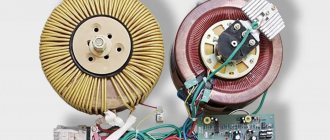
If you need a silent voltage stabilizer, look towards electronic or electromechanical devices. In electronic type stabilizers, switching between windings is carried out using semiconductor devices (i.e.
Instead of relays, thyristors or triacs are used). And in electromechanical switching is organized according to the LATR principle - a special slider moves directly along the turns of the transformer winding.
Since there are no relays in such stabilizers, they operate without clicks.
Sometimes ordinary brushes are used instead of a roller (as in electric motors). This design is less durable, but cheaper.
Despite all the advantages of electronic and electromechanical stabilizers, they can make a lot of noise (especially under heavy load).
Hum and clicks
If the voltage regulator is humming a lot, you need to check that the supply voltage is not above or below the permissible ranges. The adjustment range in most cases lies within 100-250 Volts.
Attention! Even when in good condition, the autotransformer hums evenly and not too loudly. The servo drive also makes a hum when the brush assembly moves. Relay voltage stabilizers make clicking noises during operation. This is normal, the relays (black rectangles in the picture below) switch taps from the windings to regulate the output voltage.
If the device makes a loud noise, this may indicate sparking of the brush in servo-driven models, problems with the relay, and poor contact of the internal wiring of the device.
The stabilizer is going crazy
Good day! The problem is this: A Resanta voltage stabilizer is installed in the house, rated at 8 kilowatts. Every evening for a month, at about 10 pm, something starts to click, switching something inside. At the same time, the light blinks a little (brighter or dimmer) and, accordingly, there is a clicking sound. When you turn on the load (for example, an electric stove), the voltage drops slightly and the clicking stops. The screen shows that the input voltage at this moment is dancing around 235-242 volts, the output is exactly 220. But since the light is blinking, I think it’s pindit. Question: what could it be? Jambs somewhere on the line or a malfunction of the stabilizer itself? And how to deal with this? And is it necessary?
The principle of operation of the stabilizer
Since only relays are capable of clicking in the stabilizer, it means that it is made according to a relay circuit. Each relay stabilizer has an autotransformer in its structure that increases or decreases the voltage based on the ratio of the turns of the windings. When the voltage value approaches the upper limit of the range, the device circuit switches to the autotransformer winding with a lower voltage value, and, as a result, the output voltage becomes lower. In the same way, this works in the opposite direction: when the voltage in the network deviates towards the lower threshold, the stabilizing device switches to the step-up winding of the autotransformer.
The process of switching the transformer windings is supervised by a special device - the stabilizer controller, and the switching is made through a set of power relays. It is these relays that, at the moment of connection, produce the very clicks that the user hears.
A standard stabilizer can contain from four to seven power relays. And the more voltage surges in the power supply network, the more often switching occurs and clicks are heard. Also, at these moments, the light may blink and highly sensitive equipment may turn off.
There may be several reasons for regular stabilizer clicks:
- Failure of one of the power relays. Since the relay has a limited switching resource, when it is exhausted, the contacts begin to burn and the contact resistance increases. This provokes a large voltage drop at the output of the stabilizer, and the greater the load, the greater the drawdown. Trying to correct the situation, the controller begins to switch to the next stage, where the voltage is actually higher and the controller has to switch again to the previous relay. In this way, a vicious circle of switching and clicking is formed.
- Poor condition of the electrical supply network. These could be poor contacts, the presence of many twists, or a long line with a small number of conductor sections. When trying to connect a load through a stabilization device, the mains voltage decreases at the moment of connection. Having detected this moment, the stabilizer begins to try to increase it by switching to a higher voltage autotransformer winding. But at the moment of connection, the consumer power circuit is disconnected for seconds and the mains voltage returns to its normal level. Noticing this, the stabilization device switches again to the previous level of the circuit. This creates an endless cycle of switching between power relays.
- There is a problem with the control circuit (controller). The problem is individual due to differences between the circuits for each individual stabilizer. However, typically the controller must have some offset to avoid constant tripping within certain voltage values.
Continuous clicking can lead to rapid failure of the device. Since relays are not designed for this mode of operation, the contacts can quickly burn or stick. Sticking will either lead to the burnout of the fuse at the input or to the fact that increased voltage will be supplied to the output of the stabilizer, which can lead to the failure of consumer devices.
Graphic display of the main operating modes of voltage stabilizers
In one of the previous articles, voltages were described and also brought to the network with your own hands. This material outlines the main problems with voltage stabilization devices and the possibility of repairing them yourself.
It must be remembered that a stabilizer of any type is a complex electrical or electromechanical device with many components inside, therefore, in order to repair it with your own hands, you must have a fairly deep knowledge of radio engineering. Repairing a voltage stabilizer also requires the availability of appropriate measuring equipment and tools.
Complex stabilizer device
Problems common to all types of equipment
Regardless of what class of devices you are using, there are common faults that can happen to each of them. Let's note the main ones:
- The voltage stabilizer does not turn on - the reason must be looked for in the input circuits, you need to check the serviceability of the fuses, the integrity of the cords and connectors, and switches. Usually the problem lies in these areas of the circuit, but damage to the control unit and other circuit components is also possible.
- The voltage stabilizer is making a loud noise . Note that for most devices, the presence of noise is a common phenomenon caused by the transformer, relay and servo drive operation. But if the noise level has increased significantly, you should pay attention to the condition of the cooling system fan; it may need to be replaced.
- During operation , there is constant blinking of the input and output indicators , and the quality of stabilization has deteriorated. If we talk in general about why the voltage stabilizer blinks in normal operation, then you should pay attention to the phasing when connecting to the network. In addition, the quality of grounding (or lack thereof) and the serviceability of input and output fuses can play a role. Damage to the control unit can also lead to such consequences.
- When figuring out the reason why the voltage stabilizer clicks , you should remember that for relay models this is a completely normal situation. Repair will only be required if the clicking is persistent. The reason may lie in the control board, damage to the power relays, or unsatisfactory quality of power from the main network.
- There is a significant drop in stabilizer voltage . This situation is typical when connecting a load exceeding the rated load. In addition, the drained network itself can play a role, but if the device worked normally before, the reason lies either in the power part or in the control unit.
One of the frequently asked questions concerns why the voltage stabilizer cracks. If you encounter such a situation, this is a reason to contact the service. The reason may lie in wear of the servomechanism, power relays, or poor contacts. The situation is dangerous because sparking is possible, which will cause the equipment to catch fire; do not delay repairs.
Why does the UPS make sounds: squeaking, clicking, humming and other sounds
Is the uninterruptible power supply beeping? Don't panic - this is a normal situation. The equipment is simply trying to inform its owner about some problem.
Which one exactly? You can’t explain anything here in a nutshell, but after reading this article, you can get a clear understanding of the device’s signals and recommendations for troubleshooting problems that arise.
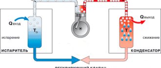
The main function of a UPS is to provide uninterrupted power to the consumer. To implement this function, the design of uninterruptible power supplies includes special modules that equalize current characteristics and storage devices (batteries) that ensure continuity of power supply.
In the event of interruptions in the operation of modules or drives, a squeak from the uninterruptible power supply is heard, signaling an emergency situation. In addition to squeaking, the UPS can hum, click and generate light signals.
To communicate with the user, a special unit is included in the design of the uninterruptible power supply, which interacts with a sound signal generator and light indicators. The result of the operation of this block is the following types of signals:
- Combined (light and sound) - the uninterruptible power supply beeps and blinks one or more indicators.
- Sound - the uninterruptible power supply crackles, beeps, clicks or hums when turned on or during operation, on one note or in short impulses.
- Light - the uninterruptible power supply flashes a red, yellow or orange indicator.
This article focuses primarily on the sound signals of the UPS, since the light indication is only available under ideal operating conditions of the device - when the UPS is in plain sight. However, for the most part, uninterruptible power supplies are hidden in cabinets, under tables and other places with difficult visibility. Therefore, the majority of users focus specifically on sounds.
Typical UPS sound signals include:
- Short beeps played at medium intensity - once every 10-30 seconds. If the uninterruptible power supply starts beeping like this, you lost power, after which the UPS switched to battery power supply mode.
- Short beeps played with increasing intensity (interval from 0.5 to 2 seconds). If the UPS beeps with a clearly decreasing interval between signals, its battery is running low. Save and shut down your device. Otherwise, you risk losing important data. Do not run the battery to zero - after this, some batteries will not be able to restore 100 percent of their original capacity.
- A monotone tone or short beeps played at high intensity and evenly spaced between beeps. The UPS beeps constantly and on one note only in case of overload. Such beeps may result from connecting devices to the uninterruptible power supply, the total power of which exceeds the recommended one.
- Short or long beeps with long intervals between beeps. If the UPS beeps like this, it has problems with the battery. It does not produce the required voltage - about 13.5 volts, therefore it cannot provide the required capacity, as well as the uninterrupted power supply process.
- Single clicks with any playback interval. In this case, there is no need to worry too much - the UPS clicks for only one reason - to compensate for high or low voltage in the network. But frequent clicks are a completely different matter. If your uninterruptible power supply is constantly clicking, then the situation with your power supply networks is close to critical - the voltage on the line drops below 180-190 volts or rises above 220-230 V.
- Long beep sounded every 2 minutes. A typical UPS constantly beeps like this only in case of problems with the power correction module. That is, electricity goes to the consumer from the outlet, bypassing all the blocks that stabilize the current characteristics through the bypass. Of course, this mode does not bode well - the consumer receives neither stable current characteristics nor autonomous power supply.
- Constant sound signal on one note, without pauses. If the uninterruptible power supply beeps and does not turn on, this means only one thing - the device has failed and overheated.
In addition, the UPS beeps when turned on - after pressing the button, the user hears a short sound signal indicating that the device has started operating.
The uninterruptible power supply device itself will give you specific recommendations. Above in the text it was discussed why the uninterruptible power supply for a computer beeps. Now you need to understand what to do if you hear a short, long or continuous beep.
Why the uninterruptible power supply beeps is correct, because it switched to battery mode. What to do in this case?
- First, save the necessary information.
- Secondly, when the signal intensity drops to 0.5-2 seconds, immediately shut down the computer normally. Otherwise, the operation of the operating system or database will be disrupted
In a word, if your uninterruptible power supply is beeping, get ready to shut down your PC or server.
If these are single clicks, then nothing. Why the uninterruptible power supply clicks is correct, because the voltage correction module equalizes the characteristics of the current from the network. If you hear the uninterruptible power supply humming, you should do the same.
Another thing is the constant clicking. The uninterruptible power supply constantly clicks only in one case - if there are serious problems with the characteristics of the power supply network, which only representatives of the energy company can eliminate.
It is important to understand whether it gives current or not. In the first case - if the UPS is working and supplying consumers - this signal tells us about an overload.
Therefore, when the uninterruptible power supply constantly beeps, and all devices are working, you just need to disconnect devices that are not needed at the moment.
The power of consumers will decrease to the recommended level and the signal will stop.
In addition, when wondering why the uninterruptible power supply constantly beeps, we must not forget that such a signal indicates a serious accident. But in this case, your UPS will refuse to supply current to the consumer, and you will only have to send it for repair.
The uninterruptible power supply beeps when turned on, turned off and during operation. Sooner or later this will start to irritate even the most phlegmatic user. As a result, there is a temptation to mute the device.
It is strictly not recommended to turn off the sound indication, because the uninterruptible power supply for a computer only beeps for business: in the event of malfunctions in the operation of equipment or critical deviations of power supply parameters from the norm.
By turning off the sound of the UPS, you will get rid of the annoying noise, while at the same time losing the opportunity to respond in a timely manner to an emergency situation. As a result, the risk of damage to serviced equipment and loss of important data increases.
The sounds of the UPS should be silenced only in one case, if the uninterruptible power supply serves the alarm system. Unwanted visitors do not necessarily need to know about the problems with the power supply of signal systems.
Shuts down under load
The voltage stabilizer does not support the load - this problem happens for a number of reasons. The first among them is increased load (consumer power). If you have not changed the connected devices, then the problem is in the stabilizer. If it does not turn off instantly, but after some time of operation, then this may be due to overheating or interturn short circuits of the autotransformer.
What to do: disassemble the device and carry out an external inspection of the windings of the autotransformer; if it is not too dusty, then check for signs of local overheating. If there is a lot of dust, clean it out
If there are signs of overheating and burning, the insulation of the windings is damaged. This is an interturn short circuit, then how to repair the stabilizer in this case? It is necessary to rewind or replace the autotransformer with one of the same or greater power. But the cost of such repairs can be comparable to purchasing a new voltage stabilizer.
Important! In servo-drive models, a number of malfunctions can be caused by brush wear and contamination of live parts with graphite shavings. During operation, the brush wears off, covering the autotransformer with graphite. Because of this, short circuits between current collectors and sections of turns and overheating can occur. In this case, you need to sweep away the graphite and clean it between turns. Make sure that the windings are laid evenly and there are no breaks. Clean the contact surface with a regular office eraser until it shines, especially the most used sector.
Failure of the servo stabilizer
Stabilizers of this class are considered the least reliable of all devices. This is due to the presence of a mechanical part that is constantly in motion. With constant surges in the input voltage, the servo drive moves current-collecting brushes along the surface of the autotransformer windings. As a result, physical wear of the contact group occurs and the brushes will need to be replaced. Note that such problems may be indicated by the fact that the voltage stabilizer beeps (only in cases where it is not a squeak from control and alarm devices).
A more complex malfunction is associated with damage to the sensors that monitor the position and limit the movement of parts of the servomechanism. If these devices fail, serious damage may occur, which will require replacement of the mechanical part to eliminate them.
Damage to the autotransformer is also typical for devices in this group. Due to constant contact with the moving mechanism, wear of the winding insulation is possible. The result of this is interturn short circuits, deterioration of stabilization and complete failure of the device.
What to do if the stabilizer turns off
Each voltage stabilizer is designed for a specific operating voltage range. In other words, the stabilizer will turn off if the voltage in the electrical network becomes higher or lower than the parameters specified in its automation. The lower threshold for turning off the stabilizer can be different - 90 or 140 Volts, it all depends on the model and type of stabilizer. The same applies to the upper voltage threshold, usually 240 Volts.
Therefore, if your power supply voltage is too low, below 140 or 90 Volts, the stabilizer will turn off automatically. This problem can be solved either by replacing the voltage stabilizer with another one that will operate on very low voltage, or by writing a statement to the Distribution Zone. The fact is that a voltage of even 190 Volts, not to mention 140, is not the norm, and you can safely make your claims about this.
The second problem due to which the stabilizer may turn off is exceeding the permissible load on it. Just like with the voltage range, each stabilizer is designed for a certain operating power. The power of voltage stabilizers starts from 500 watts and above, ending with loads for the entire house of 8 kW or more. Moreover, if you connect too many household appliances to the voltage stabilizer, it may turn off due to overload if their power is higher than that for which the voltage stabilizer is designed.
The third problem is related to short circuits in the electrical network and high inrush currents. In principle, everything is clear with a short circuit, and any protective device must respond adequately to it and automatically turn off the power to electrical appliances. As for high starting currents, some low-power voltage stabilizers (without power reserve) react very painfully by turning off when starting the same refrigerator. To prevent this from happening, the voltage stabilizer must have sufficient power reserve.
And lastly, almost all modern power supply protection devices have thermal sensors in their design. These sensors are designed to protect equipment from overheating. And if at least one of the above problems occurs, the stabilizer will turn off. For example, when the load increases above the permissible one, the stabilizer will begin to generate a lot of heat, i.e., heat up. As a result, the thermal sensor, reacting to a critical temperature, can turn off the power to the voltage stabilizer.
Basic faults
Due to unstable voltage in houses and apartments, people are forced to install voltage stabilizers (hereinafter referred to as SV) to power the entire home or to operate a specific device. As with any other type of electrical appliance, sometimes a situation arises when the voltage stabilizer does not work (broken). Internal faults in most cases are associated with power circuits: relays, triacs, servo drive control unit, etc.
Having examined the operating principles of both types of voltage stabilizers, we can conclude that it is their main components that are the most frequently broken components of the system. We are talking about a servo drive in electromechanical devices, as well as relays in relay devices.
Due to unstable voltage in houses and apartments, people are forced to install voltage stabilizers (hereinafter referred to as SV) to power the entire home or to operate a specific device.
As with any other type of electrical appliance, sometimes a situation arises when the voltage stabilizer does not work (broken). Internal faults in most cases are associated with power circuits: relays, triacs, servo drive control unit, etc.
Basic rules for installing a stabilizer
Experts suggest using the following algorithm of actions.
- Study the installation guide.
- Power outage in the house.
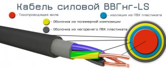
- Connection in accordance with the diagram. It is recommended to use a 4-core copper cable, the cross-section of which is determined in accordance with the power of the stabilizer (for example, a 7 kW device will require a line with a cross-section of 6 mm2).
- A two-pole circuit breaker and an RCD are installed in the panel (and when choosing equipment, it is necessary to take into account that the rated current of the residual current device must be no lower than that of the built-in circuit breaker).
- It is recommended to connect the wires from the back of the switchboard. To do this, in most cases you will need to make additional holes for the wires.
Turning on the equipment on most models is done using the “protection” and “stabilization” buttons, followed by pressing the circuit breaker lever. Information about the input/output voltage will appear on the indicator.
What are relay voltage stabilizers
We will look at the design of relay voltage stabilizers using the example of Resant stabilizers. This company has been supplying relay stabilizers to the Crimean market for quite a long time and has managed to win both fans and opponents. It is not for nothing that this type of stabilizer is one of the most popular on the market; its simplicity and reliability are appreciated by the buyer. Another factor in popularity is the price; at this time, few people can afford expensive thyristor or triac stabilizers.
The operating principle is very simple. There is a voltage boost coil (it looks like a transformer, although it does not transform anything but simply adds voltage), outputs are derived from this coil, which, depending on the input voltage, are connected in turn to the output of the device using a relay . This entire process is controlled by a control board. That's all the main parts of the stabilizer, everything else is informational and service parts.
Let's see what's inside him
As you can see, there is nothing complicated inside. Depending on the power of the stabilizer, the relays can be located both on the case and on the board. The relays are located on the board in models from 500 to 5000 VA. Over 5000 VA relays are located on the housing.
This is the principle on which this device operates
The control board analyzes the input voltage and checks it at the output of the device. Depending on the difference between the voltages, a command is given to turn on one or another relay. The switching speed of these relays is very high, which makes it possible to regulate the output voltage at a very high speed of up to 5-7 ms. But as always there is one “BUT”. Depending on the manufacturer and brand of the stabilizer, the number of stages in relay stabilizers can be from 4 to 9. The fewer control stages, the greater the voltage error at the output.
Regarding the error. You must understand one thing right away. Not a single voltage stabilizer produces exactly 220 Volts at the output . All voltage stabilizers have some kind of error from 1% to 10%. The smaller this error, the smaller the deviation from 220 Volts. If the error is 1%? We count. 220 is 100% and 1% needs to be calculated. If you remember in school they taught you to calculate percentages using this equation:
Types of voltage stabilizer malfunctions
Resanta is one of the leaders in the production of electrical equipment in our country. For more than 15 years, equipment of this brand has been known throughout Russia and the CIS countries. In many homes, Resanta stabilizers ensure stable operation of power supply networks. But, like all other devices, stabilizers require correct operating conditions or repair after a long service life. This article is devoted to possible breakdowns of Resant stabilizers, repair of damaged elements and correct operating conditions.
First, let's look at the operating principle and design of stabilizers of this brand. The main elements of Resanta stabilizers: electronic unit, voltmeter, automatic transformer, winding connection/disconnection unit.
The principle of voltage stabilization of Resanta stabilizers is the control of all stabilizers via an electronic unit. The electronic unit reads information from the voltmeter and receives input voltage data. Next, the normalized voltage is compared with the actual voltage, and only after this the electronic unit determines which stabilizer windings to turn on or off and, accordingly, how many volts to add or subtract.
The windings are turned on and off using a relay or servo. As a result, we get normal voltage at the output of the stabilizer. This is the operating principle by which all Resant stabilizers operate; they differ only in the process of voltage stabilization due to the different connection or disconnection of the windings.
Let's look at each type of equipment. produces electromechanical and relay stabilizers.
Electromechanical type of stabilizers "Resanta"
A distinctive feature of these models is the presence of a servo drive. This element switches the transformer windings. Switching occurs smoothly and without sudden jumps, so these models of stabilizers are distinguished by precise regulation of the output voltage.
The servo drive is a structure consisting of a motor and a brush. When the motor armature rotates, the brush and contact with the transformer winding begin to rotate. The brush has a width that allows two windings to contact simultaneously to avoid phase loss. The normalizer creates an error voltage that is proportional to the magnitude and is the difference between the input voltage and the voltage specified by the parameters. The error signal can have two polarities, each of which causes the motor axis to rotate in a specific direction. The brush also receives the corresponding direction.
Based on these operating features, we present possible breakdowns and malfunctions of electromechanical stabilizers. As a practical example, let's take one of the most popular models of the Resanta stabilizer ASN-10000/1-EM.
The main malfunctions of electromechanical stabilizers:
1. The more frequent the current changes in the network, the more often the motor armature and brush (servo drive) rotate. When this element rubs against the turns of the winding, it heats up excessively, causing contamination of the wires and wear of the brush, and can also cause engine failure.
2. Engine failure automatically disables the engine control cascade, which is assembled based on transistors Q2 TIP41C and Q1TIP42C.
3. After transistors Q2 TIP41C and Q1TIP42C burn out, resistors R45 and R46 automatically fail.
So, if the engine fails, be prepared to replace all of the above elements. The engine itself can be replaced with a new one, or you can undergo independent restoration, but only if you have certain skills.
To restore the engine itself:
- disconnect it from the general circuit.
- connect to a power source with a constant voltage of 5 Volts. The current strength must also correspond to certain parameters, from 90-160mA. When such a current is supplied, the motor brushes are automatically cleaned of debris using the burnout method. When applying current, change the polarity several times, this will improve the result.
- connect the motor to the stabilizer following the diagram. After this procedure, your stabilizer will return to working condition.
Relay stabilizers "Resanta"
The main malfunctions of Resanta relay stabilizers differ significantly from electromechanical malfunctions, and accordingly, repairs have distinctive features.
Relay models are characterized by intermittent voltage equalization. Operating principle: one relay turns off/on a certain number of turns of the winding or connects the turns one by one and stops at the desired one. In relay-type models, the turns are divided into groups and each has its own output, which supplies current when turned on. Resant relay stabilizers consist of four relays (the exception is the SPN models, which have five relays) and, accordingly, the number of outputs is also four. When each relay is turned off and on, the voltage surge at the output is sometimes up to 20 Volts.
The main malfunctions of relay stabilizers:
1. The main working unit of relay stabilizers is the relay; it is this part that normalizes the current. Accordingly, the more often power surges occur, the more wear it is subject to. If this component fails, it may burn or stick.
2. If the relay contacts fail, the subsequent breakdown will be transistor switches, which must be completely replaced. They vary depending on the stabilizer models. For example, the Resanta ASN-5000/1-Ts stabilizer contains D882P transistors. All transistors for Resanta stabilizers can be bought in most stores, you just need to study the modification according to the stabilizer circuit. You can restore the relay contacts yourself - remove the relay cover, release the movable contact from the spring and remove it, clean the contact from carbon deposits using sandpaper (zero), we carry out the same procedure with the upper and lower contacts, after cleaning we treat all parts with purified gasoline and We assemble according to the diagram.
Stabilizer diagnostics
After carrying out all repair work for any of the stabilizer models, it is necessary to carry out a check. For this purpose, it is best to use an autotransformer or LATR.
We connect the diagnosed stabilizer to this device and change the voltage. We use an incandescent lamp as a load. When the voltage changes, the operation of the stabilizer will be visible. And only after checking the stabilizer for correct operation, we connect it to the power supply network.
All models of stabilizers can fail due to improper operating conditions. To prevent this from happening, you must follow the rules that will help you keep the device in working condition for a long time:
1. Do not allow the stabilizer to operate for a long time at low voltage, less than 160V. If the voltage drops to a critical point, you should limit the power consumption (load) by redistributing the load and not using powerful devices that you can do without. If you experience low input voltage very often, reduce the load by 50%. For example, you have a Resanta Domingo DES-12000/1-C voltage stabilizer, its power is 12 kW; during critical voltage drops, reduce the power consumption to 6 kW. There is another way to get out of the situation with constant peak voltage drops - purchase a Resanta stabilizer from the line of stabilizers for low voltage. These stabilizer models are capable of operating at a critically low voltage of 90V!
2. The power of the stabilizer should be 10% greater than the total power of all consumers operating simultaneously. It is unacceptable to allow the device to operate at full load. More detailed power calculations for the stabilizer in our article “The need to purchase a stabilizer”
Poor voltage stabilization
If the voltage stabilizes in too large steps, and before everything was smooth, then the breakdown is close to the previous one - the switching device has failed at one or more adjustment stages. The algorithm for checking voltage stabilizer malfunctions and their elimination are described in the previous paragraph.
Attention! The characteristics of each stabilizer describe either the adjustment step or the boundaries of each stage, as well as the accuracy of maintaining the rated output voltage.
In servo-drive stabilizers, this occurs when there is a breakdown in the engine gear mechanism, as well as when the windings are dirty, as was the case in the cases described above. Gearbox malfunctions may be accompanied by an uneven buzzing or crackling sound - this is the gears slipping.
What to do: you need to disassemble the mechanism and if all parts are normal, replace the lubricant.
It is also worth noting that servo-driven MVs may lack stabilization and may not work correctly due to the failure of the semiconductor motor control switches. Then the slider with the brush moves to one of the extreme positions or does not move at all.
Shows no signs of life or other damage at all
The most frightening malfunction is when, after applying voltage, neither the indicators light up nor the output voltage appears, i.e. when the voltage stabilizer does not work at all. In this case, the control board may fail. Most often, repairs begin with a visual inspection, paying attention to:
- burnt out paths;
- swollen electrolytic capacitors;
- burnt, cracked or exploded board components;
- microcracks on soldered contacts and cold soldering.
All identified deficiencies are eliminated, and if the external inspection does not produce results, they proceed to checking the board for broken tracks and short circuits with a multimeter in resistance and continuity measurement mode. Such repair of a stabilizer may require deep knowledge of electronics, electrical circuit diagrams, and in the most difficult cases, the use of an oscilloscope to check control signals and the logic of the circuit.
That's all we wanted to tell you about voltage stabilizer malfunctions and how to fix them yourself. We hope that now you know what to do in this or that case and why breakdowns occur!
It will be useful to read:
- How to use a multimeter
- What to do if the network voltage is low
- Dishwasher malfunctions
Failures typical of relay stabilizers
The main problem is the failure of power relays. Wear of the contact group, damage to the mechanical part, burnt out coils. In outdated models, dismountable relays were used; it was possible to replace only damaged parts. Nowadays, non-repairable devices are more common, so if faults are detected, replacement will be required.
If sticking of the relay contacts is observed, cleaning it from carbon deposits will help. To do this, the body of the part is removed to provide access to the contact group. This situation is typical for stabilizers that are connected to a network prone to frequent voltage drops.
The main danger is that failure of the relay will lead to malfunctions of the transistor control switches. The problem is that these devices are also not repairable, will require replacement, and finding the necessary modification is sometimes difficult.
To minimize the consequences of malfunctions and reduce the possible cost of repairs, be sure to pay attention to the slightest changes in the operation of the stabilizer. A better solution would be regular maintenance by an experienced technician in the volumes regulated by the manufacturer. When performing such work, you can promptly notice signs of future problems and carry out preventive work that will prevent equipment failure.