Ferroresonant stabilizers became widespread in the era of the late USSR: then they were used for televisions, and even then the cost was too high. At that time, as now, this type of device was highly accurate - the error of any model is no more than 3%.
The service life of such a device can reach several decades, and therefore they are quite beneficial for installation in any industry - from medical institutions to home purposes. The only drawback is the loudness of operation: ferroresonant voltage stabilizers produce a characteristic hum, which requires sound insulation. The device treats current consumers extremely carefully: it produces an ideal sinusoid, and the error in the amplitude value is extremely small. They are also distinguished by a huge range of operating values and resistance to interference and overloads.
Ferroresonant voltage stabilizers are suitable for home use only with some reservations. In addition to the disadvantages described above, they have large dimensions and extremely high cost. This, however, does not reduce the demand for them - it only grows over the years. In terms of price and quality ratio (and especially durability), they are one of the leaders in their segment.
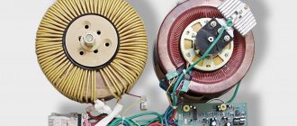
Transformer device
Connection diagram
Each phase-shifting transformer, the operating principle of which was discussed in the previous section, consists of two voltage converters that differ in their connection circuit. It includes:
- parallel transformer (PT);
- its sequential addition (we can designate it as PsT).
The primary windings of the PT are connected in parallel to the linear circuit according to the well-known “delta” type circuit (see figure above).
The secondary ones are made in the form of completely insulated coils with taps from individual turns. At one end they are connected to the primary windings of the PS, the counterparts of which are tightly grounded.
The secondary windings of a series transformer are three isolated phases connected to the main supply circuits. From the above diagram it follows that the PsT transformer is connected in a star circuit (with a tightly grounded neutral).
Important! This inclusion provides an additional phase shift of the supply voltage by 90 degrees relative to the signal coming from the station equipment. For this reason, another name for these devices is phase shifter or cross transformer
They are capable of working both independently and as part of units that include converters of other types. It is also clear from the connection diagram that the load is connected to it through the phase secondary windings of the PsT
For this reason, another name for these devices is phase shifter or cross transformer. They are capable of working both independently and as part of units that include converters of other types. It is also clear from the connection diagram that the load is connected to it through the phase secondary windings of the PsT.
Phase correction effect
The consequences of phase correction can be presented in the form of corrections that are made to the circuits after installing phase shifting devices in them. For successful operation of such transformers, the following points must be taken into account when designing them:
- The loads generate a supply voltage consisting of the sum of two components (the source vector and the value introduced by the phase shifter).
- It is possible to achieve compensation for losses in the line by changing the second component.
- To control the characteristics of the PT, adjustable taps in the form of a rheostat are provided in the secondary winding of the PT.
- When the position of the regulator slider changes, the second component of the phase sum changes, compensating for the shift that has occurred in the line.
In this way, the phase difference between the source and consumer voltage vectors, which arises due to the distributed parameters of the lines and load unevenness, is corrected.
Ferroresonance phenomena in electrical networks
The main factors that give rise to ferroresonance phenomena in electrical networks are elements of capacitive and inductive types. They are capable of forming oscillatory circuits during switching periods. This effect is especially noticeable in power type transformers, linear booster transformers, shunt circuits and similar devices that are equipped with massive windings.
This phenomenon comes in two types: resonance of currents and voltage.
Voltage ferroresonance is possible when there is inductance in the network, characterized by a nonlinear current-voltage property. This characteristic is characteristic of inductors, where the cores are made from ferromagnetic components. This is especially true for rectifiers from the NKF line. This negative phenomenon is caused by a small indicator of resistance of ohmic and inductive types in relation to power transformers.
What types of stabilizers are there?
Voltage stabilization can be implemented in various ways.
By design, stabilizing devices can be divided into two groups:
- Electromechanical devices;
- Electronic devices;
The first group includes stabilizers with a servo motor. The second group includes the following devices:
- Relay stabilizers;
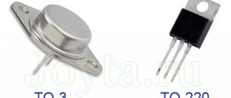
- Devices based on semiconductor switches (thyristors, triacs);
- Double conversion devices;
- Ferroresonance stabilizers.
Each device has certain advantages and disadvantages. They are clearly visible when comparing technical parameters, so to choose a specific model you need to know the operating principle of each stabilizer for your garden or home.
Stabilizer with relay switching
A relay voltage stabilizer equalizes the mains voltage by switching the windings of a power transformer. The principle of its operation is extremely simple. The input voltage is supplied to the primary winding of the power transformer and at the same time to the monitoring and control board. The secondary winding is divided into equal sections and the number of turns in it is greater than in the primary. That is, the transformer, if necessary, can increase or decrease the supplied voltage. The control board includes a rectifier, a controller and transistor switches that control electromagnetic relays.
If the network voltage deviates from the nominal value by a certain amount, the controller turns on the relay through a transistor switch. It changes the transformation ratio with its contacts, that is, switches the secondary winding to increase or decrease. As a result, the output voltage is constantly kept within tolerance, but it will never be equal to 220V, since by switching sections of the winding, the device allows a stepwise rather than a smooth change in voltage. But the more relays are used in the device circuit, the higher its accuracy.
The relay stabilizer has the following positive qualities:
- Good switching speed;
- Large input voltage range;
- Undistorted voltage waveform;
- Affordable price.
Disadvantages of a relay device:
- Step switching;
- Low accuracy;
- Noise during operation;
- Possible burning of contacts.
Relay stabilizers also have a power limitation, which is determined by the inability of the relay contacts to switch too high currents.
Stabilizer with servo motor
An electromechanical voltage stabilizer, like a relay one, works using a power transformer. The device has a control board, but it does not control the adjustment using a relay, but selects the angle of rotation of the servomotor. A carriage with a carbon roller or brush is installed on its axis, which moves along the winding of the power transformer. The output voltage changes in proportion to the angle of rotation.
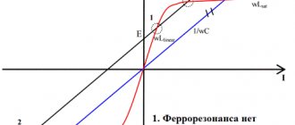
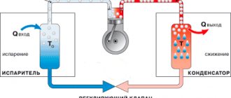
Operating principle of ferroresonance stabilizers
The primary winding, which receives the input voltage, is located in section 2 of the magnetic circuit. It has a significant cross-section to keep the core in an unsaturated state. At the input voltage forms magnetic flux F2.
The output voltage is created at the terminals of the secondary winding. The load located in the 3rd section of the core is connected to it, and has a small cross-section and a saturated state. when the network voltage and magnetic flux deviate, its value remains almost unchanged, and the EMF also does not change. When the magnetic flux increases, some part of it will be closed along the magnetic shunt.
Flow F2 becomes sinusoidal. If flux F2 approaches the amplitude value, then the third section goes into saturation, and the magnetic flux stops increasing, and flux F1 appears. As a result, the flow along the magnetic shunt will be closed only when magnetic flux No. 2 is comparable in magnitude to the amplitude one. This creates a non-sinusoidal flow F3, and the voltage also becomes non-sinusoidal.
The presence of a capacitor allows the device to operate with an increased power factor. And the stabilization coefficient depends on the slope of the horizontal curve 2 to the abscissa. This area has a large slope, so it will not be possible to obtain greater stabilization without auxiliary devices. Direct current transfer makes it possible to achieve increased gain.
How to choose a stabilizer
The list of parameters by which stabilizers are selected necessarily includes:
- load power or supplied rated current;
- output voltage;
- type of network (single-phase - three-phase).
Information about the stability of the network and the level of impulse noise in it will be of great help.
When determining the rated power, the powers of all consumers of the protected network are summed up. To estimate the power of the rated load, the current load capacity of the input circuit breaker is multiplied by 220 V.
All other things being equal, single-phase models of linear stabilizers are chosen, taking into account that modular designs are more convenient to maintain.
Take into account aesthetic parameters and the number of output sockets, Figure 5.
Fig.5. Single-phase stabilizer version
It is advisable to make the final choice taking into account the manufacturer and place of manufacture. To determine the quality of south-eastern-made equipment produced without control by leading Western companies, it makes sense to study specialized forums. This approach allows us to draw an adequate conclusion about the quality of the device.
In addition to technical parameters, the availability of service must be taken into account. Please note that there is a large selection of 220-volt single-phase and 380-volt three-phase devices on sale
Stabilizers with a wide adjustment range and output voltages of other ratings are often supplied to order
Please note that there is a large selection of 220-volt single-phase and 380-volt three-phase devices on sale. Stabilizers with a wide adjustment range and output voltages of other ratings are often supplied to order.
The industry produces a wide range of household voltage stabilizers, which allows you to select a specific device model taking into account a specific application.
The massive nature of the stabilizer market is determined by the large number of manufacturing enterprises operating in it, offering their products through a partner network. Therefore, before purchasing, you should perform a careful multi-criteria selection of the product.
Electromechanical voltage stabilizer
What is this device? Essentially, this is a transformer (voltage booster) that independently regulates the voltage on the supply loop. That is, there is no need to tighten anything if there is a need to add a few volts, as is done with relay analogues.
Currently, the scope of application of electromechanical stabilizers is quite extensive. These are not only household premises and offices; these devices are also in demand in places where high-precision electronic equipment is used. For example, in medical institutions.
Classification of stabilizers
The main division of electromechanical voltage stabilizers is based on the voltage itself. That is, they are single-phase (220 volts) and three-phase (380 volts). It is clear that the former are most often used in the private sector and in office premises, the latter in large institutions and production. Although today, when the population has the opportunity to build their own large houses, which house a huge amount of household appliances, three-phase voltage stabilizers began to be installed in them.
In terms of their design, the devices are represented by wall-mounted, floor-mounted, table-top models, and can be mounted both horizontally and vertically. That is, the manufacturers took into account all the options for a convenient location, depending on the location of the device. It should be noted that these voltage stabilizers have a very accurate voltage setting, operate without extraneous interference, have shown themselves to be excellent under short-term high overloads, and at the same time have a fairly wide range of stabilization of the voltage itself.
And the third position of separation is the power of the device. Currently, manufacturers offer a very wide range of models in this regard. Here you can find simple low-power voltage stabilizers 500 kVA, and high-power units up to 20,000 kVA. It should be noted that purely structurally, the two positions (220 and 380 volts) differ from each other in that the first option has one transformer and one brush block, while the design of the second may contain two or three transformers.
Advantages and disadvantages
Electromechanical voltage stabilizers have a wide range of advantages over other analogues:
- widest input voltage range;
- high accuracy of the output voltage indicator, virtually no distortion;
- safe operation at high short-term input voltage, regardless of whether it is 220 volts or 380;
- low sensitivity (almost complete absence) to the operating frequency makes it possible to use three-phase voltage stabilizers at industrial facilities;
- silent operation even with the highest voltage surges in the supply network.
Not without its drawbacks:
- unfortunately, this is not an electronic device, so the design of the electromechanical stabilizer contains moving elements that will have to be replaced with new ones every 5-6 years;
- Once every ten years, manufacturers recommend changing the servo drive of the brush block;
- if the voltage in the supply network drops below 180 volts, then almost all manufacturers do not guarantee its increase at the output to the stated rated value;
- single-phase analogues are not designed to work at low temperatures, so it is best to install them inside heated rooms;
- not a very high stabilization speed, of course, when compared with other models;
- Whether there is a need to classify this as a disadvantage, everyone decides for himself, but the operation of the servo drive of the electromechanical stabilizer is accompanied by a click that lasts a fraction of a second.
DIY ferroresonant voltage stabilizer
The ferroresonant circuit is the simplest for DIY production. Its operation is based on the magnetic resonance effect.
The design of a fairly powerful ferroresonant type rectifier can be assembled from three elements:
- primary choke;
- secondary throttle;
- capacitor.
However, the simplicity of this option is accompanied by a whole set of inconveniences. A powerful normalizer made using a ferroresonant circuit turns out to be massive, bulky and heavy.
How to choose equipment: key characteristics
The main parameters when choosing a stabilizer are the permissible input voltage range and the power of the connected equipment
Sometimes it is necessary to pay attention to the accuracy of setting output values, adjustment speed
Phasing
There are three types:
- single phase current;
- two-phase current;
- three-phase current.
To stabilize voltage in multiphase networks, the use of specialized devices is required.
Power
The power of the stabilizer must match the power of the connected load. A device operating at maximum load will fail, but a more powerful one with a low load will work reliably, while having low efficiency.
When calculating the total load of consumers, take into account the fact that the equipment is not always turned on at the same time.
Active load
Heating devices and incandescent lamps are characterized by active power consumption, which, when calculated, fully corresponds to the total power. Such devices produce heat and light. They do not contain inductance or capacitance. A resistive load converts electrical energy into light and heat.
Reactive load
Contains capacitance and inductance:
- electric motor;
- vacuum cleaner;
- food processor;
- household tool.
That is, all devices that contain electric motors. When calculating, it requires the use of a coefficient. Since the power consumption will be greater than with a reactive load.
Power reserve
When choosing power, they are guided by the fact that normal operation is ensured if there is a reserve of at least 30%. That is, if the load power is 3500 W, then the stabilizer power is at least 5000 W.
Power reserve is important when the mains voltage is low. The lower the input voltage, the more the load capacity is reduced.
Stabilized voltage range
Each device remains operational only within a narrow voltage range. The acceptable range varies depending on the type of stabilizer used. For example, electromechanical ones have 180 - 240 V, and inverter ones have 110 - 250 V.
If the voltage goes beyond the specified limits, the protection will trip and the device will shut down.
Stabilization accuracy
Stabilization accuracy is the ability of a device to maintain the output voltage within the specified parameters. Electromechanical and inverter stabilizers have the best accuracy. Relay or thyristor ones have a stepwise change in the output voltage within 5V. This change is noticeable when using certain types of lighting fixtures and is expressed in brightness jumps.
Installation method
Depending on the requirements and power, I install stabilizers in several ways:
- for the entire network;
- for separate groups of devices;
- for each consumer.
It often happens that several low-power stabilizers are more cost-effective than one powerful one. Added to this is an increase in reliability.
Availability of information display
The information display on the instrument panel is a necessary functional element that allows you to visually monitor the status of network parameters. It will show:
- input and output voltage;
- load;
- warning;
- overload;
- overheat.
Manufacturer
Equipment from leading manufacturers is reliable, but also expensive. Many, wanting to save money, purchase products from unknown manufacturers at a minimal cost, although this choice has an extremely low guarantee of proper operation. And it can even be the cause, for example, of a fire.
High frequency stabilizer models
Compared to relay models, a high-frequency voltage stabilizer (the circuit is shown below) is more complex, and more than two diodes are used in it. A distinctive feature of devices of this type is considered to be high power.
The transformers in the circuit are designed to withstand high noise levels. As a result, these devices are able to protect any household appliance in the house. The filtering system in them is configured for various jumps. By controlling the voltage, the current value can be varied. In this case, the limiting frequency indicator will increase at the input and decrease at the output. Current conversion in this circuit is carried out in two stages.
Initially, a transistor with a filter at the input is used. At the second stage, the diode bridge is turned on. In order for the current conversion process to complete, the system requires an amplifier. It is usually installed between resistors. Thus, the temperature in the device is maintained at the proper level. Additionally, the system takes into account the power source. The use of the protection unit depends on its operation.
Operating modes
The operating modes of stabilizers depend on a number of factors. The power indicator and the class of the device have a direct impact. The power characteristics of the device may be different; they must be selected taking into account the type of electrical equipment being connected.
The operating modes of the rectifier depend on the following types of load:
- inductive;
- active;
- capacitive
Active loading in its pure form is extremely rare. It is necessary only in those circuits where the variable value of the device has no restrictions. Capacitive loads can only be used for those rectifiers that have low power.
The most popular manufacturers
Today there are more than a dozen Russian and foreign companies that successfully produce voltage stabilizers. Each product differs in design, performance, power type and stabilization method. Each company has products with similar parameters. But only when using them in practice do we learn about both the pros and, unfortunately, the cons. Some companies have already lost their quota of trust, but the rest, thanks to quality products, are trying to maintain their brand. Here are the manufacturers that are popular among consumers in our country:
Russian brands - Polygon, Norma M, Stabvolt, Cascade;
Chinese brands: Solby, Fnex, Sassin, Voltron, Voto;
Western brands: Ortea, Orion.
Foreign brands, although of higher quality, are inferior in terms of demand to Chinese and Russian products. The reason for the dislike of Russian consumers lies in prices. If the domestic product is quite good and much cheaper, then why overpay?
Impact on technology
Ferroresonant voltage regulators may affect the following equipment:
- TVs. If you connect the device to a TV, then you will notice a significant reduction in the raster. Also some color rays may be disrupted.
- Radios. This type of technology may lose its sensitivity. The receiver's output power may also be significantly reduced.
- Tape recorders. The power output of these devices may drop significantly. Erasing records can also get worse in this case.
As you can see, ferroresonant products can have their drawbacks. If you don’t know which ferroresonant stabilizers to choose, then we’ll tell you now.
Home appliances are constantly improving. That is why manufacturers of ferroresonant stabilizers are also trying to improve their products. They are improving its circuitry, which will allow it to cope with high loads.
Now these products can accurately adjust the voltage. The process of changing and stabilizing voltage occurs using a transformer. He can add or subtract coils as needed.
Tips for choosing
Household appliances are constantly being modernized and improved. Therefore, manufacturers of ferroresonant voltage stabilizers are striving for modernization. They improve the quality of the circuit to cope with large overloads. Innovative devices of this type are characterized by increased speed, adjustment accuracy and long service life.
The modes are determined by the power of the devices and their type. Devices with a reactive load include those that have an electric motor - air conditioners, heaters, fans.
If you need to buy a ferroresonant device, then you need to take into account the location of its connection. This is usually performed at the entrance to the room, or in close proximity to a household device. If you plan to install for all devices, then it is better to select a stabilization system for the required power and connect the stabilizer immediately after the energy meter.
Reliability and maintainability
Equipment reliability is determined by many factors. The most obvious of them are the quality and quantity of components used in the production of products.
If we assume that the manufacturers of both stabilizers guarantee high quality of the element base, then the quantitative component should be assessed.
We do not take into account fasteners, paint and other unimportant components. Let's compare the number of electrical elements.
The classic stabilizer is built simpler and includes from 50 to 80 elements and produces a minimum of heat during operation.
In inverter components there are 3 to 5 times more components and the heat generation is quite significant, which necessitates the need for a large radiator or fan.
And now a little theory. The reliability of a product depends on the reliability of each input element and the number of these elements. In addition, an increase in temperature by 10 degrees reduces reliability (various figures are given in the literature, up to a reduction in service life by 2 times).
If we take the reliability of one element equal to 0.99, then the total reliability of three elements will be: 0.99x0.99x0.99=0.97 (i.e., the probability of failure is 3%), and if there are 10 elements, this indicator will be equal to 0. 90 (i.e. 10% failure rate).
Of course, modern items have reliability above 0.99, but the tendency for reliability to decrease as the number of items increases is quite significant.
It can be argued that if we have a large number of elements, our televisions, computers, and washing machines work normally for years. But do not forget that household appliances do not work for a full day, and the stabilizer must work constantly without turning off.
The practice of using classic stabilizers shows that they can work for 10 years or more. There are simply no such statistics for inverter models yet. We know that any equipment, even the highest quality, sometimes requires repair. And the consumer is not indifferent to how easy or difficult it will be to carry out this repair.
During the warranty period and if service is available, repairs will be made at least free of charge, although the timing will likely depend on the complexity of the repair. And in other cases, problems may arise related to the maintainability of the product.
The maintainability of stabilizers is determined by several parameters.
This is installation density, ease or difficulty of access to elements. This is the need to have one or another equipment for dismantling and installing the product being repaired, the availability of instruments and stands for its adjustment and testing. This is the availability of the element base in case of need to replace faulty parts. And, of course, requirements for the qualifications of repair personnel.
Classic relay stabilizers have a low installation density and their element base does not involve rare and scarce microcircuits. The instruments used are simple, and you can usually just use LATR as a stand. Therefore, the requirements for the qualifications of repair personnel are not particularly high; we can say that qualifications at the level of a garage radio amateur are sufficient. It is clear that under such conditions repairs will not be a big problem for the consumer.
With inverter stabilizers the picture is completely different. The layout here is dense, and the bulk of the elements are SMD, specialized microcircuits. To install and dismantle SMDs, you will need to purchase special equipment, and replacing such microcircuits is impossible without a good soldering station. In addition, these elements themselves will not always be easy to purchase, and in small localities their purchase will be almost impossible. An oscilloscope with a decent bandwidth is a must. It is clear that the qualifications of the personnel must be no lower than that of an engineer. And most likely you will have to contact the manufacturer.
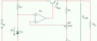
Design and principle of operation of an electronic stabilizer
An electronic stabilizer usually consists of the following components:
- input and output voltage meters;
- a control chip that analyzes data from meters and, if necessary, turns on the voltage conversion process;
- transformer with the ability to switch windings to regulate voltage;
- a block of electronic keys (thyristors or triacs), which controls the switching of windings.
The operating principle of the electronic stabilizer can be described as follows:
When the voltage in the supply network changes, the difference between its actual and nominal value is recorded. The control microprocessor sends a signal to turn on a specific power switch that switches exactly that section of the transformer winding, the transformation ratio of which will provide the output voltage value closest to the nominal value.
Thus, the principle of operation of electronic stabilizers is in many ways similar to the operation of relay-type devices. If in the latter the switching of the necessary windings of the autotransformer is carried out using electromechanical relays, then in electronic devices instead they are used power semiconductor switches that are much faster - thyristors or triacs.
Also, the design of the electronic stabilizer provides for operation in bypass mode - when the mains voltage is within normal limits, electricity is directed bypassing the transformer and directly supplied to the consumer.
Thus, electrical appliances are powered through an electronic voltage stabilizer as follows:
- If the parameters of the electric current correspond to the standard ones, it passes through the bypass without loading the main circuits of the stabilizer.
- If there is a drop or increase in voltage, the meter at the input of the stabilizer records this change.
- The stabilizer control chip issues the appropriate command and the electronic key unit is activated.
- The transformer windings are included in the circuit, which convert the voltages to the desired level.
Stabilized sources
Inverter
Inverter-type voltage stabilizers convert alternating voltage into direct voltage and accumulate energy by charging intermediate capacitors.
Next, using an electronic generator, the direct voltage is converted back into alternating voltage, but with stable characteristics.
These devices are successfully used to ensure the operation of medical and sports equipment.
Electric machine
This stabilizer works on the principle of converting electricity into kinetic energy using an electric motor and then converting it back into electricity using a generator. The accumulation of kinetic energy and stabilization of the output voltage during supply voltage dips is carried out by a flywheel rigidly connected to the rotors of the engine and generator.
Such stabilizers are usually used to stabilize voltage in three-phase voltage systems. Even with strong surges and dips in the supply network voltage, the rotation speed of the flywheel remains almost unchanged, therefore the output voltage of the generator is practically unchanged.
Pulse bursts are damped due to the high inertia of the flywheel. The speed of rotation of the flywheel depends not on the magnitude of the input voltage, but on the phase frequency.
These systems were widely used to power computers. Currently rarely used. Mainly at sites of strategic importance.
Power electronics
Continuous electronic stabilizers regulate the voltage by changing either the resistance of the regulating element, usually a transistor, or turning the regulating element on and off at a high frequency (tens of kilohertz), and controlling the time the regulating element is on and off (most often an IGBT transistor). This control method is called PWM (pulse width modulation).
Stabilizers using high-frequency PWM are currently the most advanced implementation of an AC voltage stabilizer, and, if executed correctly, are closest to the concept of an “ideal stabilizer.” Unlike inverter-type stabilizers, they do not pre-convert alternating voltage to direct voltage, but the input alternating voltage is directly converted, which provides them with high efficiency and reasonable cost.
Ferroresonance in a voltage transformer
When a voltage transformer is connected to the network, series-combined LC circuits are formed in it, which are a resonant-type circuit. When an inductive element with a nonlinear current-voltage property is connected in series to a capacitive-type element, the voltage in this zone of the circuit is characterized as active-inductive.
After a certain time period, the voltage value on the inductive element becomes peak, the magnetic circuit is energized, and the voltage on the capacitive type component continues to increase. Ferroresonance in a voltage transformer occurs when the voltage of the inductance and capacitive element becomes equal.
The rapid transition of the applied voltage from the active-inductive type to the active-capacitive type is referred to as “phase reversal”. This effect is dangerous for electrical appliances.