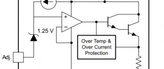
Devices that are included in the power supply circuit and maintain a stable output voltage are called voltage stabilizers. These devices are designed for fixed output voltages: 5, 9 or 12 volts. But there are devices with adjustment. They can be set to the desired voltage within certain accessible limits.
Most stabilizers are designed for a certain maximum current that they can withstand. If you exceed this value, the stabilizer will fail. Innovative stabilizers are equipped with a current blocking, which ensures that the device is turned off when the maximum current in the load is reached and are protected from overheating. Along with stabilizers that maintain a positive voltage value, there are also devices that operate with negative voltage. They are used in bipolar power supplies.
The 7805 regulator is manufactured in a transistor-like package. Three conclusions are visible in the figure. It is designed for a voltage of 5 volts and a current of 1 ampere. There is a hole in the case for fixing the stabilizer to the radiator. The 7805 is a positive voltage device.
The mirror image of this regulator is its 7905 negative voltage counterpart. There will be a positive voltage on the case, a negative value will be sent to the input. -5 V is removed from the output. In order for the stabilizers to work in normal mode, 10 volts must be supplied to the input.
Technical characteristics of the stabilizer LM338:
- Providing output voltage from 1.2 to 32 V.
- Load current up to 5 A.
- Availability of protection against possible short circuit.
- Reliable protection of the microcircuit from overheating.
- Output voltage error 0.1%.
The LM338 integrated circuit is available in two housing options: a metal TO-3 housing and a plastic TO-220 housing:
Types of 12V stabilizers
Such devices can be assembled using transistors or integrated circuits. Their task is to ensure the value of the rated voltage Unom within the required limits, despite fluctuations in the input parameters. The most popular schemes are:
- linear;
- impulse.
The linear stabilization circuit is a simple voltage divider. Its work lies in the fact that when Uin is applied to one “arm,” the resistance changes on the other “arm.” This keeps Uout within the specified limits.
Important! With such a scheme, if there is a large spread of values between the input and output voltages, the efficiency drops (a certain amount of energy turns into heat), and the use of heat sinks is required.
Pulse stabilization is controlled by a PWM controller. By controlling the key, he regulates the duration of the current pulses. The controller compares the value of the reference (set) voltage with the output voltage. The input voltage is supplied to the switch, which, opening and closing, supplies the received pulses through a filter (capacitor or inductor) to the load.
For your information. Switching voltage stabilizers (SV) have higher efficiency and require less heat removal, but electrical impulses during operation create interference for electronic devices. Self-assembly of such circuits has significant difficulties.
Classic stabilizer
Such a device includes: a transformer, a rectifier, filters and a stabilization unit. Stabilization is usually carried out using zener diodes and transistors.
The main work is done by the zener diode. This is a kind of diode that is connected to the circuit in reverse polarity. Its operating mode is breakdown mode. The principle of operation of the classic CH:
- when Uin < 12 V is supplied to the zener diode, the element is in the closed state;
- when Uin > 12 V enters the element, it opens and holds the declared voltage constant.
Attention! A supply of Uin exceeding the maximum values specified for a certain type of zener diode leads to its failure.
Diagram of a classic linear CH
Integral stabilizer
All structural elements of such devices are located on a silicon chip, the assembly is enclosed in an integrated circuit (IC) package. They are assembled on the basis of two types of ICs: semiconductor and hybrid film. The former have solid-state components, the latter are made of films.
Main! Such parts have only three terminals: input, output and adjustment. Such a microcircuit can produce a stable voltage of 12 V with an interval of Uin = 26-30 V and a current of up to 1 A without additional wiring.
CH circuit on IC
Examples of application of the LM338 stabilizer (connection circuits)
The following examples will show you some very interesting and useful power circuits built using the LM338.
Simple regulated power supply on LM338
This diagram is a typical LM338 harness connection. The power supply circuit provides an adjustable output voltage from 1.25 to the maximum supplied input voltage, which should not exceed 35 volts.
Variable resistor R1 is used to smoothly regulate the output voltage.
Simple 5 Amp Regulated Power Supply
This circuit produces an output voltage that can be equal to the input voltage, but the current varies well and cannot exceed 5 amperes. Resistor R1 is precisely selected to maintain a safe 5 amp limiting current limit that can be drawn from the circuit.
Regulated 15 amp power supply
As mentioned earlier, the LM338 microcircuit alone can handle only 5A maximum, however, if it is necessary to obtain a higher output current, in the region of 15 amperes, then the connection diagram can be modified as follows:
In this case, three LM338 are used to provide high current load with the ability to regulate the output voltage.
Variable resistor R8 is designed for smooth adjustment of the output voltage
Digitally controlled power supply
In the previous power supply circuit, a variable resistor was used to regulate the voltage. The circuit below allows you to obtain the required output voltage levels using a digital signal supplied to the bases of the transistors.
Current stabilizers on transistors
To stabilize the current through LEDs, you can use well-known solutions:
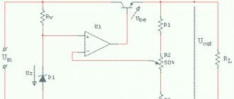
Figure 1 shows a diagram whose operation is based on the so-called. emitter follower. A transistor connected in this way tends to maintain the voltage at the emitter exactly the same as at the base (the only difference will be the voltage drop across the base-emitter junction). Thus, by fixing the base voltage using a zener diode, we obtain a fixed voltage on R1.
Next, using Ohm's law, we obtain the emitter current: Ie = Ue/R1. The emitter current practically coincides with the collector current, and therefore with the current through the LEDs.
Conventional diodes have a very weak dependence of forward voltage on current, so they can be used instead of hard-to-find low-voltage zener diodes. Here are two variants of circuits for transistors of different conductivities, in which the zener diodes are replaced by two conventional diodes VD1, VD2:
The current through the LEDs is set by selecting resistor R2. Resistor R1 is selected in such a way as to reach the linear section of the I-V characteristic of the diodes (taking into account the base current of the transistor). The supply voltage of the entire circuit must be no less than the total voltage of all LEDs plus about 2-2.5 volts on top for stable operation of the transistor.
For example, if you need to get a current of 30 mA through 3 LEDs connected in series with a forward voltage of 3.1 V, then the circuit should be powered with a voltage of at least 12 Volts. In this case, the resistor resistance should be about 20 Ohms, the dissipation power should be 18 mW. The transistor should be selected with a maximum voltage Uke not lower than the supply voltage, for example, the common S9014 (npn).
Resistance R1 will depend on the coefficient. gain of the transistor hfe and the current-voltage characteristics of the diodes. For S9014 and 1N4148 diodes, 10 kOhm will be enough.
Let's use the described stabilizer to improve one of the LED lamps described in this article. The improved diagram would look like this:
This modification can significantly reduce current ripple and, consequently, the brightness of the LEDs. But the main advantage of the circuit is to normalize the operating mode of the LEDs and protect them from voltage surges during switching on. This leads to a significant extension of the life of the LED lamp.
From the oscillograms it can be seen that by adding a current stabilizer for the LED on a transistor and a zener diode to the circuit, we immediately reduced the ripple amplitude several times:
With the ratings indicated in the diagram, the power dissipated by the transistor is slightly more than 0.5 W, which makes it possible to do without a radiator. If the capacitance of the ballast capacitor is increased to 1.2 μF, then the transistor will drop ~23 Volts, and the power will be about 1 W. In this case, you cannot do without a radiator, but the pulsations will drop almost to zero.
Instead of the 2CS4544 transistor indicated in the diagram, you can take 2SC2482 or a similar one with a collector current of more than 100 mA and a permissible voltage Uke of at least 300 V (for example, the old Soviet KT940, KT969 are suitable).
The desired current, as usual, is set by resistor R*. The zener diode is designed for a voltage of 5.1 V and a power of 0.5 W. Common SMD LEDs from Chinese light bulbs are used as LEDs (or better yet, take a ready-made lamp and add the missing components to it).
Now consider the diagram presented in Figure 2 . Here it is separately:
The current sensor here is a resistor, the resistance of which is calculated using the formula 0.6/Iload. As the current through the LEDs increases, transistor VT2 begins to open more strongly, which leads to stronger blocking of transistor VT1. The current decreases. This way the output current is stabilized.
The advantage of the scheme is its simplicity. The disadvantage is a fairly large voltage drop (and therefore power) across transistor VT1. This is not critical at low currents (tens and hundreds of milliamps), however, a further increase in the current through the LEDs will require installing this transistor on a radiator.
Also, instead of a bipolar transistor, you can use a p-channel MOSFET. The circuit below is a powerful lamp using two 10-watt LEDs and a 40-watt IRF9510 in a TO-220 package (see specifications):
The current through the LEDs is set by selecting resistor R1. VT1 - any low-power. LEDs - Cree XM-L T6 10W (see specification) or similar.
Transistor VT2 and LEDs must be placed on a common radiator with an area of at least 900 cm2 (this is without forced cooling). The use of thermal paste is mandatory. The radiator fins should be thick and massive in order to remove heat as quickly as possible. Galvanized profiles for drywall, herring cans and pot lids are absolutely not suitable!!!
If such power is not needed, you can reduce the number of LEDs to one. But in this case you will have to lower the supply voltage by 3-3.5 volts. Otherwise, the power consumption will remain the same, the transistor will heat up twice as hot, and the light will be twice as bad.
To reduce the power, it would be more correct to leave both LEDs, but reduce the current, for example, to 2A - then the power will drop from 20 to 12 W, and the lifespan of the LEDs will increase many times over. And the radiator area can be reduced to 600 cm2.
Instead of IRF9510, you can take, for example, IRF9Z34N (19A, 55V) or NDP6020P (24A, 20V). See for yourself which ones are at your disposal. If you have nothing at all, it's time to buy cheap:
| Name | characteristics | price |
| IRF9510 | P-channel, 100V, 4A | 209 rub. / 10 pieces. |
| IRF9Z34N | P-channel, 55V, 19A | 124 rub. / 10 pieces. |
| NDP6020P | P-channel, 20V, 24A | 120 rub. / 10 pieces. |
| Cree XM-L T6 | 10W, 3A | 135 rub. / PC. |
Well, the simplest current stabilizer circuit for LEDs on a field-effect transistor consists of just one transistor with a short-circuited gate and source:
Instead of KP303E, for example, BF245C or a similar one with a built-in channel is suitable. The principle of operation is similar to the diagram in Figure 1, only the ground potential is used as the reference voltage. The magnitude of the output current is determined solely by the initial drain current (taken from the datasheet) and is practically independent of the drain-to-source voltage Usi. This can be clearly seen from the output characteristic graph:
In the diagram in Figure 3, a resistor R1 is added to the source circuit, which sets some reverse gate bias and thus allows you to change the drain current (and therefore the load current).
An example of the simplest current driver for an LED is presented below:
A field-effect transistor with an insulated gate and a built-in n-type channel BSS229 is used here. The exact value of the output current will depend on the characteristics of the particular instance and the resistance R1.
These are, in general, all the ways to turn a transistor into a current stabilizer. There is also a so-called current mirror, but it is not suitable for LED lamps. So let's move on to microcircuits.
Connection diagram
And here is the connection diagram for such stabilizers. This circuit is suitable for all stabilizers of the 78XX family.
In the diagram we see two capacitors that are sealed on each side. These are the minimum values of capacitors; it is possible, and even desirable, to supply a higher value. This is required to reduce ripple at both the input and output. For those who have forgotten what ripple is, you can look at the article on how to obtain a constant voltage from an alternating voltage.
Checking with a multimeter
Before using 78L05, it is better to check with a multimeter by ringing for a short circuit between the contacts. If there is no short circuit, then you can check further. At the input, you need to apply a voltage of at least 7 V or more, but within the maximum permissible. To do this, you can use a regular 9 V crown. It is advisable to connect a load to the output, for example a 1 kOhm resistor.
When supplying power, polarity must be observed. The negative should be connected to the common terminal (Gnd), and the positive to the input (VIN). The output voltage is taken from Gnd and VOUT. It should be 5 V (±8%), depending on the modification of the microcircuit.
Stabilizer 7812 - technical parameters
This stabilizer is housed in a TO-220 housing, which has three terminals. It is capable of stabilizing a voltage of 12 volts, which makes it possible to use it in various electronic devices.
Technical data:
- Output type – permanent.
- Output current – 1 ampere.
- The lowest operating temperature is 0 degrees.
- The highest operating temperature is 125 degrees.
- Number of pins – 3.
- Rated voltage is 12 volts.
- The lowest input voltage is 14.5 volts.
- The highest input voltage is 27 volts.
- Housing type – TO – 220 AB.
Most often, such stabilizers are used in one part of the circuit when there is no point in creating an entire power supply for devices. The 7812 regulator uses internal current overheating protection. This makes the unit at its base very reliable. With good cooling by the radiator, the 7812 stabilization device is capable of delivering a current of 1 ampere. The highest input voltage should be no lower than 14.8 V and no higher than 35 V.
Such stabilizers were created for sources of a certain constant voltage of 12 V; using additional elements, these devices can be converted into stabilized current sources with the ability to adjust.
Stabilizer pinout.
The stabilizer operation scheme is suitable for all microcircuits of this type:
Three-terminal stabilizers
For many non-critical applications, a conventional 3-pin regulator will be the optimal choice. It has only 3 external outputs. It is factory set to a fixed voltage. The 7800 series are representatives of stabilizers of this type. The last two digits indicate the voltage. We have already talked about one of this series earlier (7805)
The figure shows how easy it is to make a stabilizer, for example, at 5 volts, using one circuit. A capacitance connected in parallel with the output optimizes transition processes and keeps the output resistance low at higher frequencies. If the device is located far from the filter, then an auxiliary input capacitor must be used. The 7800 series is produced in metal and plastic cases.
lm7812 stabilizer 12 V
The 7812 voltage stabilizer changes the voltage up to 20 V to 12 V. This device was often used to create a stable operating voltage for low voltage devices: audio amplifiers, microcontrollers, lighting lamps.
An unstable voltage value, and even a variable value, can be connected to the input stage. LM 7812 is a stabilizer included in the 78xx series of microcircuits. They differ only in the output voltage, other parameters remain the same.
For better heat dissipation, a cooling radiator is attached to the stabilizer body. It can be removed from old devices from the board. Instead of a radiator, you can use tin from cans, cutting it into strips and drilling holes in them for mounting with a screw.
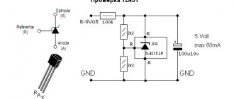
Package stabilizers L7812CV + check
Simple DIY CH
What is a voltage stabilizer
A 12-volt voltage stabilizer for LEDs, backlights of automotive on-board systems is quickly and conveniently performed using microcircuits: LM317, LD1084, L7812, KREN 8B and similar devices. Several diodes, a resistance and the microcircuit itself are the components of such a circuit.
Stabilizer on LM317
Depending on the manufacturing option of the LM317 case, the arrangement of parts on the board is selected.
LM317 with heatsink mount
Making a stabilizer comes down to the following:
- a resistance with a nominal value of 130 Ohms is soldered to the output (Vout);
- a wire supplying voltage for stabilization is connected to the input contact (Vin);
- the adjustment input (Adj) is connected to the second terminal of the resistor.
When connecting LED lights, strips, etc. as a load. no radiator required. Assembly takes 15-20 minutes with a minimum of parts. Using a simple formula, you can calculate the value of resistance R to obtain a certain value of the permissible load current.
CH circuit on LM317
Circuit on the LD1084 chip
The use of this microassembly will help maintain the 12 V voltage constant for LED illumination devices connected to the vehicle’s on-board network.
Datasheet LD1084
Here, to assemble a homemade CH, the following is included in the circuit binding circuit of the microcircuit:
- two electrolytic capacitors of 10 μF * 25 V;
- resistors: 1 kOhm (2 pcs.), 120 Ohm, 4.7 kOhm (can be constant);
- diode bridge RS407.
The device is assembled as follows:
- the voltage removed from the rectifier diode bridge is supplied to the input of LD1084;
- the emitter of the KT818 transistor is connected to the contact that controls the stabilization mode (Adj), the base of which is connected through two single-column resistors to the power supply circuits for the headlights (low and high);
- the output circuit of the microcircuit is connected to resistors R1 and R2, as well as a capacitor.
By the way. Resistor R2 can be taken not as a variable, but as a tuning one, using it to set the output voltage to 12 V.
SN for on-board network
Stabilizer on diodes and assembly L7812
A similar microcircuit in conjunction with a diode and capacitors can supply LEDs with a stable voltage of 12 V.
The scheme is built according to the principle outlined below:
- The 1N401 Schottky diode passes current from the positive terminal of the battery through itself and supplies it to the input of the microcircuit. In this case, the “+” of the electrolyte (330 μF capacitor) is also connected to the cathode of the diode;
- a load circuit and a “+” capacitor with a capacity of 100 μF are connected to the output of L7812;
- all negative terminals (from the battery and both electrolytic capacitors) are connected to the control input of the microcircuit.
Electrolytic capacitors are selected for a voltage of at least 25 V.
12 V stabilizer circuit on IC L7812
The simplest stabilizer is the KREN board
Schemes using rolls are quite popular. This is the name for ICs whose markings include combinations of the letters KR and EN. These are powerful SNs that allow you to supply a current of up to 1.5 A to the load. They have a stable 12 V output when a voltage of up to 35 V is applied to the input.
The circuit using this microcircuit is assembled like this:
- voltage from the positive terminal of the battery (rechargeable battery) to the bank input is supplied through a 1N4007 diode, it protects the battery circuit from reverse voltages;
- the negative terminal of the battery is connected to the control electrode KREN;
- The output voltage is supplied to the load.
If necessary, the microcircuit is screwed to the radiator.
KR142EN8B, connection diagram
Assembling 12 V voltage stabilizers with your own hands using linear and integrated MV circuits is not difficult. In this case, it is necessary to monitor the heating temperature of the housing of the elements and, when T0C is higher than permissible, install them on heat sinks (radiators).
Checking the functionality of the L7805CV
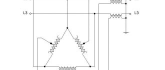
How to check the functionality of the microcircuit? To begin with, you can simply ring the terminals with a multimeter; if in at least one case a short is observed, then this clearly indicates a malfunction of the element. If you have a power source of 7 V or higher, you can assemble a circuit according to the datasheet given above and apply power to the input; at the output, use a multimeter to record the voltage at 5 V, so the element is absolutely operational. The third method is more labor-intensive if you do not have a power source. However, in this case, you will also receive a 5 V power supply in parallel. It is necessary to assemble a circuit with a rectifier bridge according to the figure presented below.
To check, you need a step-down transformer with a transformation ratio of 18 - 20 and a rectifier bridge, a further standard kit, two capacitors for the stabilizer and that’s it, the 5 V power supply is ready. The capacitor values here are overestimated in relation to the L7805 connection diagram in the datasheet, this is due to the fact that it is better to smooth out voltage ripples after the rectifier bridge. For safer operation, it is advisable to add an indication to visualize the device being turned on. Then the diagram will look like this:
Read also: Pressure cut-off sensor for compressor
If there are a lot of capacitors or any other capacitive load on the load, you can protect the stabilizer with a reverse diode to prevent the element from burning out when the capacitors are discharged.
The big advantage of the microcircuit is its fairly lightweight design and ease of use, if you need power of one value. Circuits sensitive to voltage values must be equipped with such stabilizers to protect elements sensitive to voltage surges.