Design features and main characteristics
Let's look at how a contact box is structured using the example of a CI ultrasound (see Fig. 2)
Figure 2. Location of contacts in the ICC
Contacts marked 0, A, B and C are used for the power circuit, and terminals numbered 1 to 7 are used for the current section. How to enable instrumentation will be described in the next section.
The instrumentation design is a contact group housed in a plastic box made of impact-resistant and non-flammable polycarbonate. The dimensions of this model are 68x220x33 mm.
Operating voltage and current parameters are 380 V and 16 A. The insulating properties of the material allow it to withstand short-term excesses of up to 2000 V and 25 A. Brass is used to make live parts. It can be replaced with galvanized steel, but the service life of such contacts becomes shorter. In this regard, manufacturers of famous brands prefer brass.
Other performance characteristics:
- the module can be used at temperatures from -40 C° to 60 C°;
- permissible humidity – no more than 98%;
- for connection, wires with a minimum cross-section of 0.5 mm 2 and a maximum cross-section of 4 mm 2 are used;
- this model is available with a degree of protection IP20;
- service life - up to 30 years.
Some models (for example, BTS or KIP-5/25) are available with a transparent cover (see Fig. 3). Considering that devices of this type are subject to mandatory sealing, this design feature has obvious advantages, since it allows you to monitor the condition of a group of contacts.
Purpose of instrumentation
KIP stands for test transition box. It serves to connect the electric meter to operating networks and allows you to de-energize power lines along a selective phase connected to the meter.
Transition test box
The design of the instrumentation has the form of a contact group located in a plastic box made of non-flammable and impact-resistant polycarbonate. Brass is used to produce current-carrying elements. The module is operated at a temperature of −40 to 60 degrees Celsius and a relative humidity not higher than 98%. To connect it, wires with the smallest cross-section are installed. Its useful life reaches 30 years. The degree of protection of the box according to GOST 14254-96 IРЗ0.
The test box itself is used to carry out the following work:
Thanks to these three points, it is possible to reset the electric meter without removing the voltage from the installation. The last paragraph indicates that it is permissible to connect a sample meter if there is a need to check the device without disconnecting it.
The test box is a very important device that is used when it is necessary to replace the meter without disconnecting from the power supply. I note that there is always a certain group of consumers for whom a power outage, even for a short time, is unacceptable - for example, for a number of equipment this can become very critical. The test terminal box helps simplify the entire process, without the need to de-energize and reinstall a technical measuring device.
Device design
ICC design
Typical transition boxes are available in several designs, differing in appearance and shape. Most often they have the form of a rectangular block with thick walls made of durable and non-flammable material (carbolite or plastic). In this design, the box resembles a substrate with groups of terminals placed on it, forming the so-called “clamping cage”.
Through holes are made along its edges, used for attaching the IKK to the walls of the distribution board. Its connecting contacts are made of brass or galvanized steel (sometimes phosphor bronze is used for this). Some box models are equipped with additional elements such as a flange or lever, which simplifies the installation process.
Transition contacts are made in the form of spring-loaded plates or screw clamps placed on conductive plates made of brass, tin or steel. Their use is explained by the resistance of these materials to corrosion and high conductivity. The top of the block is closed with a transparent plastic cover, securely fixed to the base. When operating the test device together with an electric meter, its cover is also sealed. For this purpose, it is provided with through ears for hanging a seal or a small hole for a control screw (screw). The transparency of the protective coating allows you to visually control the disconnection of contact groups.
Instrumentation diagram
The test transition box is manufactured in several varieties, which differ in shape and external design. Often, they are made in the form of a rectangular box with thick walls made of strong material that does not support the combustion process. Thus, it has the appearance of a substrate, with groups of terminals located on it, forming a “clamp cage”. Holes are formed along each edge of the structure, passing through and necessary for fastening to the walls of the IKK distribution panel. Connecting contacts are made of steel or brass. To simplify the installation process, an additional flange or lever can be installed.
Instrumentation connection diagram
For transition contacts, screw retainers or spring-loaded plates are used, located on conductive brass, tin or steel plates. These metals are highly resistant to corrosion and have excellent conductivity. At the top, the block is closed with a transparent lid, which is firmly fixed to the base. When used with a meter, the lid is also sealed. Especially for sealing, there is a hole for a screw or ears for fixing the seal. Thanks to the transparent coating, which provides additional protection, the disconnection of contact groups is controlled.
Devices are important when laying new power lines or when it is necessary to improve them. During the installation of a meter with IKK, the requirements of the PUE, which regulate the rules for the use of boxes, are observed. At the terminals of the box, it is allowed to combine wires made of metals of the same type that are electrochemically compatible.
It is important not to overtighten screw connections. The maximum tightening force can be 2.5 Nm. This ensures terminal integrity. Defects and damage are also unacceptable. At the installation site, the housing is fixed exclusively mechanically - by screwing or securing it using special latches. The box, as a rule, is installed in the electrical cabinet immediately next to the meter.
Attention If you need a test transition box, I recommend paying attention to the instrumentation produced by Priborenergo.
The IKK installation instructions help you install it correctly. Despite the rather primitive type of construction, it does not require special maintenance. This fact further indicates its absolute reliability. All procedures for installation, dismantling and opening with subsequent sealing must be carried out exclusively by specialists in this industry. Before installation, I recommend that you read the documentation; it will resolve many of your questions (you can download the necessary files below).
Despite the fact that such a product does not require maintenance, I still advise periodically tightening the contacts, especially if there are screw-type clamps. This is really important, since the wire may become slightly deformed when heated, which leads to loose contacts.
Source
ICC box design
Enterprises produce test boxes of various types and shapes. But mostly you can find rectangular plates made of durable shockproof and fireproof composition. Carbolite or high-strength plastic is used as fireproof raw materials.
Installation in the panel
This plate looks like a substrate on which the terminal blocks are located, creating a clamping circuit. At the boundaries of the block there are small holes used for fixing the ICC to the electrical box.
Note! For the production of electrical contacts, tin or carbon steel, as well as heat-resistant bronze and copper are used. Many types of test boxes are equipped with additional parts, such as a spigot or a handle, to simplify installation
The transition parts are similar to spring gear or iron platforms. These elements are located on current-conducting plates made of copper, tin, and steel. These materials are resistant to temperature and humidity changes and are quite durable.
If the use of a test box is necessary to connect an energy meter, then a seal is placed on the lid; for this purpose it is equipped with small holes for sealing or holes for a control part. Thanks to the transparent cover, you can monitor the visual status of the device. The rules for connecting blocks to energy metering devices are described in detail below.
Terms of use
Installation, dismantling, opening and installation of seals on the box are carried out only by specialists in this field who have a license obtained from Energonadzor and have received the required level of permission to work.
All test boxes can be classified according to different characteristics. To begin with, they are divided by the type of network where they will be used.
Next you can find boxes necessary for use in 220 V and 380 V networks. They are also distinguished by weight, appearance, and size.
Connecting transformers to electricity
IKK test boxes can be round, oval or square. In addition, they are divided by:
- purpose. For use in conjunction with instrumentation or for switching operations only;
- installation method. You can find boxes used for mounting in a distribution block;
- number of contact categories. Produced ICCs can have three or more electrical contacts;
- type of fastening. There can be screw, push, barrier and fixed fastenings. Also, some devices have cable protection;
- number of contact rows. Can be with one or more tiers;
- execution - straight and angular;
- type of cable used.
Note! The main difference between the boxes is always the diagram by which they are connected. Depending on the factory and application, the ICC can be connected in different ways
All major energy companies are involved in the creation and distribution of test boxes. The main differences may lie in the materials used in manufacturing.
Unless a person has the appropriate tools or electrical skills, it is not advisable to attempt to install the test adapter box yourself. Incorrect installation may lead to incorrect operation of the meter or short circuit of the wires. If a defect in the wires or terminal blocks is discovered through the transparent cover, then you need to call a specialist to your home immediately.
Important! You are not allowed to break seals yourself. This is done by a specialist with permission
Arbitrariness may result in fines being imposed.
Many craftsmen recommend purchasing devices with additional protection for the wires so that in the event of a fire the fire does not pass through them. The cost of such products varies within 250 rubles. Products made from more expensive material have a price from 300 to 500 rubles.*
Adapter box connection diagram
You can connect the IKK yourself without any difficulties. But only a special person can perform opening and sealing. Such a box will help not only simplify the work with the meter, but also make it safer.
*Prices in the article are for April 2022.
Junction box for external and hidden wiring: types, classification + installation instructions
A traditional element of electrical networks is a junction box for external and hidden wiring, protecting current-carrying conductors (cables) at their connection points. It has a simple design and does not cause installation difficulties, the main thing is to choose the right accessory
But this issue deserves special attention
When choosing an electrical element, it is necessary to take into account a number of important parameters. Among them: the type of electrical wiring, the material of the walls and the junction box itself, as well as other factors.
We will tell you how not to get confused in the variety of offers, help you choose the best option and perform competent installation.
Test box: transition box for electric meters, box installation
When installing measuring instruments in three-phase power circuits, special attention is paid to bringing the controlled quantities to a form convenient for connection to an electric meter. For significant current loads reaching 1000 Amperes, special converting devices are used for this - current transformers (CTs)
For significant current loads, reaching 1000 Amperes, special converting devices are used for this - current transformers (CTs).
If they are present, maintenance and repair of metering devices connected to the line becomes significantly more complicated.
Purpose and features of IKK
Test box for meter
The PUE specifically stipulates the requirement regarding the connection of the meter to existing electrical networks in terms of its switching through a device called a test box (TBC). When using it, it is possible to short-circuit the secondary circuit of the measuring transformer, which makes it possible to de-energize the supply lines for each of the phases supplied to the meter.
Connecting the current transformer through the test box allows you to turn the procedure for replacing and checking the meter into a completely safe activity. In addition, in this case it is not necessary to disconnect the load from the supply line.
Electricity meter test boxes are especially in demand in the following situations:
- for bypassing control circuits;
- if there is a need to completely disable them;
- if necessary, block voltage in each phase;
- for connecting a measuring device (electricity meter) to a controlled line.
The need for IKK boxes is also explained by the fact that there is a special group of consumers, each of whom cannot be disconnected from the power grid even for a short time.
Taking into account the fact that periodically there is a need to carry out work with the meter, the IKK test terminal box significantly simplifies all operations.
In this case, there is no need to de-energize the power line and install a replacement shunt in place of the measuring device.
Scheme for connecting the meter via instrumentation
Only qualified personnel who have undergone safety training and have an electrical safety group of at least third, for installations up to 1000 V, are allowed to work with KKI boxes and meters.
Scheme of bales and contact locations
The metering device is connected to the terminal test box according to a pre-prepared diagram. When using PUE, all meters with three phases must be connected via a combined box, as well as converters.
The disconnection sequence is performed in the following order:
To ensure ease of installation, absolutely all wires are marked. The beginning of the current phase windings and the common terminal are also indicated here. Conductors are connected from the top side of the box from the meter, and then disconnected one by one. The area of its plates must be larger than the contacts used for taps from transformers. The plate is closed with a lid, and the device can then be used.
Nuances of use
Although this type of product does not require additional maintenance, it is still recommended to tighten the contacts some time after commissioning, especially in the case of screw terminals. This is due to the fact that during operation the wire heats up and is slightly deformed, and this leads to a weakening of the contact. There is no such requirement for clamp boxes. At the same time, it will be more convenient to use, since when you turn off the measuring device, no additional tools will be needed.
But it is also worth noting that installation, dismantling, opening and sealing of the box must be carried out by specialists who have a certificate issued by Energonadzor and who have received the required clearance group.
Adapter test box - purpose, characteristics, connection options
According to accepted standards, there is a special group of consumers who cannot be disconnected from the power supply system even for a short time. But what to do when a three-phase meter needs to be replaced for metering circuits or a testing laboratory needs to perform verification using a reference control device?
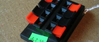
Under the conditions described above, refer to the first section in the code of practice for electrical installations. It states that to connect a meter with a current transformer (the abbreviation “CT” will be used in the text), an adapter test box must be installed, for example, such as in Figure 1.
Figure 1. KI-10 (LIMG.301591.009)
Purpose
This device is used when it is necessary to install metering circuits based on electricity meters with transformer connection. This solution allows you to do the work without disconnecting consumers:
- connect an exemplary metering device to the panel;
- perform shunting and disconnection of current circuits;
- perform disconnection of a certain phase.
The first action is performed when testing control devices, the rest - when replacing them.
Scope of use of test boxes
ICC for an electricity meter can most often be found when:
- shunting control circuits;
- network blackout;
- if you need to block the voltage in a certain phase;
- during connection to the controlled line of the measuring device (electricity meter).
The need to use test boxes is also explained by the fact that there is a certain category of consumers, each of which is not allowed to be de-energized even for a short period of time.
For your information! Due to the fact that it is constantly necessary to work with the meter, the test terminal block greatly facilitates all actions. In this case, there is no need to disconnect the entire power line and install a replacement shunt in place of the measuring device.
The parameters and properties of transition boxes are described in detail below. When purchasing, you must select a device that matches the specific characteristics of the meters.
Brief information
LLC NPO "MMK" was registered on January 14, 2008 by the registrar Inspectorate of the Federal Tax Service for the Verkh-Isetsky district of Yekaterinburg. Head of the organization: liquidator Guseva Inessa Vitalievna. The legal address of LLC NPO "MMK" is 620041, Sverdlovsk region, Ekaterinburg, Uralskaya street, building 57 building 2, apartment 41.
The main activity is “Production of other finished metal products not included in other groups”; 15 additional types of activity are registered. The organization LIMITED LIABILITY COMPANY RESEARCH AND PRODUCTION ASSOCIATION “METMASHKOM” was assigned TIN 1222398117, OGRN 3273383369108, OKPO 25164177.
The organization LIMITED LIABILITY COMPANY RESEARCH AND PRODUCTION ASSOCIATION "METMASHKOM" was liquidated on October 12, 2022. Reason: Liquidation of a legal entity.
Transition test box (CTB)
Hello, dear readers and guests of the Electrician's Notes website.
In many of my articles, especially about connecting meters through current transformers, I mentioned to you about the test adapter box (terminal block). In short, KIP.
So today I would like to talk about it in more detail.
So, what is this box (terminal block) for?
In Chapter 1.5, clause 1.5.23 of the PUE 7th edition it is said that electrical energy metering circuits must be connected to special clamps or test boxes (terminal blocks).
By the way, anyone who wants to test their knowledge or prepare for an electrical safety exam online, I suggest doing so directly on the website. For you, I have specially prepared a whole section “Online tests on electrical safety” for different groups.
The test adapter box (TUB) is intended for:
- the ability to “short-circuit” (bypass) current circuits
- disconnecting current circuits
- disconnecting voltage circuits for each phase
- connection of a standard electric meter
The first three points are necessary to replace the electric meter without removing the voltage from the electrical installation. The last point applies to connecting a model or reference electric meter in order to check the metering device without disconnecting the consumer’s load.
The photo above shows a transition test box that meets the technical specifications MKYUR.301 591.000 TU. It has the following technical characteristics:
- voltage up to 380 (V)
- maximum current up to 10 (A)
- degree of protection - IP20
- weight - about 500 (g)
- overall dimensions of the box 33x68x220
Test box connection diagram
Below see the diagram for connecting the meter through the test terminal block to a four-wire 380/220 (V) network:
And here is a photo from above of the adapter terminal block with the designation of terminal numbers:
To “short-circuit” (bypass) current circuits, you simply need to screw M4 screws into the following holes:
In the photo above, the screw on terminal 1 is not screwed in, but on terminals 2, 4 and 6 the screw is screwed in.
When screwed in, these screws complete the circuit through a common busbar located on the back of the terminal block.
By the way, to protect the common busbar from short circuits to the housing, a cardboard gasket is used on the reverse side.
After the current circuits are short-circuited, you can remove (remove) the jumpers.
To disconnect the voltage circuits for each phase, you need to unscrew the screws and remove the corresponding jumper.
I forgot to mention that all jumpers and terminals at the transition test box (CTB) are made of brass, because... it is less susceptible to corrosion and also has better electrical conductivity compared to steel.
The test box is closed with a lid with a screw for sealing.
Instrument covers are either black (not transparent) or transparent. The latter has a significant advantage in that the state (position) of the contacts and the connection diagram of the meter can be seen without opening it.
Example of connecting a test adapter box (TUB)
Below I will give you an example of connecting a test box. A few days ago I installed electricity meters on two input cells of the boiler station, which were later connected to the ASTUE system.
The metering panel was installed on the wall near the ASU assembly.
Meters, test and interface boxes are also installed there. Metering circuits (current circuits and voltage circuits) are connected to current transformers and ASU buses using PV-1 copper wires with a cross-section of 2.5 square meters. mm, laid in corrugation.
I will not go into detail on the meter connection diagram, because... I recently wrote an article about connecting a three-phase meter through current transformers to a four-wire 380/220 (V) network, in which you can familiarize yourself with everything in detail.
In conclusion, I recommend that you watch my video, where I more clearly talk about connecting the test box using the example of a Mercury 230 ART-03 meter connected through three current transformers to a 400 (V) network:
Addition. In this article I looked at one of the options for connecting a test box. In practice, there is another common scheme, which I describe in detail in the video (using the example of a Mercury 230 AM-03 meter connected through three current transformers to a 400 V network):
Connection example
The meter must be connected through the test box strictly according to the diagram. It is better to consider using a real example of connecting an induction meter TsE6803 V 100/10 T1. According to the requirements of the PUE, three-phase circuit current metering devices are connected through current transformers and an adapter box.
You might be interested in Electrical engineering and electronics as the basis of physics
TOP-0.66 with a reduction factor of 200/5 can be used as current transformers. For the case under consideration, a test adapter box B3179 produced by METZ “Mytishchi Electrotechnical Plant” is suitable. Its weight does not exceed 0.4 kg, and its dimensions are: 68x220x33 mm . The sequence of disconnecting this equipment will be as follows:
- A meter, a test box and current transformers are installed in the switchboard.
- The transformers are connected in a star configuration, and their common terminal is grounded.
- Wires with a cross-section of at least 1.5 mm² are laid from the current converters to the junction box.
- Three wires are also drawn from the energy meter, but the cross-section in this case is already 2.5 mm².
- For convenience, all wires are marked, that is, all three phases and the beginning of the current windings and the common terminal are designated.
Conductors from the meter are inserted from above the ICC and connected in turn to a contact group having a wider plate area, and from the current transformers from below.
The connection will look like this:
- 1 terminal of the meter - the beginning of the current winding of the first phase;
- Terminal 2 - first phase voltage;
- 4 terminal of the meter - current winding of the second phase;
- 5 terminal - potential difference of the second phase;
- 7 terminal of the meter - incoming wire of the current winding of the third phase;
- 8 terminal - third phase voltage;
- 9 meter terminal - common wire;
- Terminal 10 - reserve.
Jumpers are installed between terminals 3,6 and 9 using the plates included in the kit. This is done by screwing an M4 screw through the jumper to the connected plates, using specially made holes.
After this, the IKK is closed with a lid and the system is ready to turn on. If there is a need to remove the meter, then the jumpers are simply untwisted, thereby breaking the circuit going to the meter.
Device installation
IKK installation diagram
The devices are in demand when laying new electrical lines and when it is necessary to modernize them. During installation, the requirements of the PUE regarding the rules of operation of test boxes must be met. According to the regulations, to place the ICC it will be necessary to prepare a specially equipped place, protected from entry by unauthorized persons and accessible to service personnel.
It is allowed to connect only wires made of homogeneous metals that are electrochemically compatible at the terminals of the box.
The tightening force for contact screw connections should not exceed 2.5 Nm, which guarantees the safety of the terminals. In addition, they must not have any damage or traces of obvious defects. Fixing the IKK body at the installation site is carried out only mechanically - by screwing it or securing it using special latches. The box is usually mounted in the electrical cabinet immediately after the electric meter.