About grounding
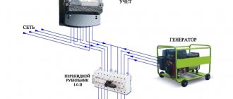
Before you connect an electric stove, you must realize that this appliance has a lot of power.
Therefore, it must be grounded without fail. The simplest option is to conduct grounding through the grounding system of a private house. Of course, if it exists. Typically, the ground loop is formed outdoors and inserted into the distribution panel, where a bolt is installed. It is to this that the earth is attached with a nut.
Grounding system in a distribution boardSource legkovmeste.ru
If there is no grounding in the house, then it can be done. This is a minor problem that can be resolved quickly. To do this, three pins made, for example, from steel reinforcement, are driven in on the street near the house. Instead, you can use any metal profile. The pins are driven to a depth of up to 2 m at the corners of an equilateral triangle and connected to each other with the same reinforcement or a steel strip 3 mm thick and 30 mm wide.
After which the triangular circuit is connected to the distribution board with the same strip or wire rod with a diameter of 6 mm. A bolt is installed in the shield, to which all grounding wires from household appliances will be connected. Or maybe from all sockets.
How to properly make a grounding loop on the streetSource build-experts.ru
There is an option without grounding. To do this, the yellow-green cable is not connected to the contact on the stove. It is simply bent to the side and isolated. In this case, you need to be very careful with the stove. Eg:
- The installation of the stove must be carried out in such a way that the person operating it cannot simultaneously grab the metal surface of the stove or its elements with one hand and any conductive element with the other. For example, for a sink, faucet, mixer, etc.
- You need to place a mat near the electric stove, which would become an intermediate layer between the person and the floor. Ideally, this mat will be dielectric.
- In the distribution board, it is better to replace the circuit breaker for the stove with a difautomatic circuit breaker with a rating of 30 A.
Choosing a place for an electric stove
Before choosing a place to install the stove, ask the owner how it will be convenient for her
It is here that she will create her culinary masterpieces, her opinion is important to take into account, however, with all that, you need to follow some rules, namely: If the kitchen floor has unevenness or slopes, you must first level the platform for the stove, or select a flat area
If the kitchen floor has unevenness or imperfections, you must first level the area for the stove, or select a flat area.
Although the stove has special, adjustable legs, with the help of which you will adjust the position relative to the horizon, it will be easier to do this if the floor plane is fairly level than to then build unnecessary stands and pads.
It is very convenient if it is possible to move the stove without disconnecting from the power supply. If the electric stove is connected directly, without special sockets, it is necessary to provide a sufficient cable length.
You should still have the ability to do cleaning, as well as freedom of access to the stove for maintenance purposes.
The stove emits a powerful electromagnetic field during operation, so it will be better if there are no radiation-sensitive radio devices nearby.
The key point in choosing a location is the ventilation system - an exhaust hood; if it is already available, then without a major restructuring of the entire kitchen, there are minimal options for the location of the stove. When building a house, plan in advance where and what you will install.
Briefly about the main thing
There are two connection schemes for an electric stove: single-phase or three-phase.
An electric stove must be grounded.
A separate automatic circuit breaker and an RCD must be installed on the supply circuit of the stove.
The connection of the plate can be made through a socket or terminal block. In this case, the socket must be of a safe design and can withstand a current of at least 32 A.
If you choose a material, then there is only one correct answer to the question of what cable is needed to connect an electric stove - only copper with a cross-section of at least 4 mm².
Is it possible to make wiring from the stove socket?
According to them, additional sockets, switches or lamps cannot be connected to the supply line for an electric stove. For a single-phase network, a three-core wire with a cross-section of 6 mm 2 is used, and for a three-phase network, a five-core wire is used, but with a smaller cross-section. Once you select the right wire, you need to protect it.
Interesting materials:
What is a hammer? What is a letter header? What is Zaire? What is a headband and ornament? What is female alcoholism? What is a female harem? What is Liquid Luminizer? What is a VRM zone? What is a zoomorphic ornament? What is a net salary?
Stove connection diagram
Models of electric stoves on the market use different connection schemes. It is necessary to take this fact into account when choosing a particular model. Some manufacturers produce devices capable of operating both in a single-phase network with a voltage of 220 V, and in two and three-phase at a voltage of 380 V.
Single-phase connection
The overwhelming majority of people live in apartments with an electrical network made according to a single-phase circuit with a voltage of 220 V. In this case, the connection of electrical appliances is carried out with a three-core cable, observing the color marking of the cores.
- phase wire white or brown;
- neutral conductor blue;
- the ground wire is yellow-green.
In the terminal block of an electric stove intended for a single-phase network, you can find markings that ensure unambiguous connection of electrical equipment:
- terminal L is used to connect the phase wire;
- terminal N is for neutral;
- PE terminal for grounding.
In universal models, instead of one terminal L, you will find terminals L1, L2, L3, which, when connected, must be connected with standard jumpers supplied with the device in accordance with the operating instructions.
Two-phase connection
A two-phase connection is a rare option for connecting to the power grid in our country. In a network of this type, the voltage between the neutral conductor and any of the phases is 220 volts, between two phase conductors 380 V. To connect to this network, you need to prepare a four-core cable and a two-pole circuit breaker in the electrical panel.
Color marking of cores in this case:
- the first phase wire is white or brown;
- the second phase conductor is black;
- neutral conductor blue;
- the ground wire is yellow-green.
In the terminal block of an electric stove intended for a two-phase network, you can find markings that ensure unambiguous connection of electrical equipment:
- terminal L1 is used to connect the first phase;
- terminal L2 is used to connect the second phase;
- terminal N is for neutral;
- PE terminal for grounding connection.
Three-phase connection
A three-phase network with a voltage of 380 V, as a rule, is available only to owners of private houses. It is the most rational option for connecting electric stoves. When connecting a three-phase network, the load is evenly distributed between the phases, reducing the current consumed by the electric stove.
In the case of a three-phase network, you need a five-core submarine cable and a three-pole circuit breaker in the electrical panel.
The terminal block of the plate will contain the following terminals:
- terminal L1 is used to connect the first phase;
- terminal L2 is used to connect the second phase;
- terminal L3 is used to connect the third phase;
- terminal N is for neutral;
- PE terminal for grounding connection.
Connecting the electric stove
Connecting the electric stove
The connection procedure remains the same for networks with any number of phases. There are only a few nuances that you will learn about further. The connection will be made through an outlet.
First step
We choose a place to install the device. The electric stove is classified as a high-power electrical receiver. To ensure its reliable and safe operation, we install a plug socket with a grounding contact on the wall closest to the stove. In this case, the current rating of the socket should be 32-40 A. The socket for a single-phase electrical network will have three contacts, for two- and three-phase networks - five.
Socket
Second step
We install a separate circuit breaker in the panel. If the network is two- or three-phase, we install a three-way 16 A switch. In the case of working in a single-phase network, we install a single-way circuit breaker. The switch rating should be 25-32 A.
Single-phase electric stove connection (most common)
Third step
We install the wire to connect the electric stove. In two- and three-phase networks we use a 5x2.5 cable of the VVGng brand; for connection in single-phase mode we use a 3x4 cord of the same brand. We pull the wire from the electrical panel to the plug socket of our electric stove.
Power cable VVGng 5×2.5
Fourth step
We connect the wire to the outlet in accordance with one of the above diagrams. Close the socket cover. We work very carefully, observing established standards. If the connection is made using a three-core cable, then connect the brown wire (it can also be white) to the phase connector of the installed electrical outlet, connect the blue wire (can be white with a blue stripe) to the “zero” connector, and connect the yellow-green wire with grounding connector. The wires of a five-core cable are most often colored brown, white and red. The order of their connection, as well as the features of marking the socket connectors, were discussed earlier in the description of the circuits.
Fifth step
Connect the plug to the flexible wire of the electric stove
In this case, be sure to pay attention to the marking features of the plug. The element is connected in the same way as an electrical outlet.
Sixth step
We connect the flexible wire to the stove. At this stage, much depends on the model of the device being installed and the number of phases in the home electrical network. In general, manufacturers provide connection diagrams for their stoves in the accompanying instructions or on the back covers of the units. We follow the manufacturer's recommendations.
It is recommended to tin the ends of the flexible wire before installing it in the terminal clamps - this will ensure the most reliable contact.
Seventh step
We separate the power cable of the electric stove in the panel, and then strip the ends of the wires. We connect the phase conductors of the supply cable to the strip terminals of the machine. We connect the “zero” core to a common bus for all zero conductors. Only the yellow-green core remained unconnected. In modern systems, such wires are connected to ground buses. In older TN-C type networks there are no ground buses. What to do? Read on.
Arrangement of jumpers in the Hans electric stove
How to connect an oven
If the equipment is installed complete with a hob, the total power of the equipment is taken into account. If it is less than 3.5 kW, the use of an outlet is acceptable. The connection of functional parts is carried out according to the manufacturer’s diagram with subsequent connection to a common power line.
The cabinet is installed horizontally in cabinet furniture. Level the level using screw supports. For control, use a building level. Leave ventilation gaps of 4-8 cm.
Connection to the power supply is carried out according to the points in the official instructions. The procedure is similar to the installation of an electric furnace discussed above. As in the previous option, it is recommended to use a separate machine and RCD for reliable protection of users and equipment.
Socket with grounding 220 V for 16 and 32 A - technical characteristics
If we take the European part of the continent and all of Russia, then the standard voltage (U) in the network is from 220 to 240 V. Conventional sockets are designed for a voltage of 220 V with a load of no more than 3.5 kW.
The operation of such sockets is limited to household appliances of low power and are designed for a current (I) of 16A.
If we take more powerful electrical appliances (electric stoves, ovens and other electrical appliances), then other sockets are provided for them with a maximum current (I) of 32 A and a maximum permissible power of 7 kW.
The AC frequency for Europeans and Russia is 50 Hz, which means that all electrical equipment is designed for this frequency.
The degree of protection from dust (objects) and moisture varies among sockets. Some have no protection at all, and some have IP20, IP44, IP54 and others. The higher the IP, the higher the protection. For example, IP54 - “5” protects from all kinds of objects completely and partially from dust, “4” protects from splashing water.
The following brands of sockets have IP54: EL-BI EVA, ABB EVA, VIKO, EKF, DelUMO and others. Such sockets are installed in damp areas, for example, in bathrooms.
Product materials and designs
Basically, in our time, cases (not the lid) are made of ceramics and non-flammable plastic. Of course, ceramics have an advantage, because polymers are always inferior to ceramics in terms of durability and heating.
Copper or brass contacts are screwed onto the body using screws. Some sockets use springs to ensure better contact with the plug.
There are modifications of sockets in which the phase and zero holes are closed with curtains inside under the cover. Such sockets are good to use in places where there are children.
If you look at the PUE, then according to the requirement, a three-wire system (phase, neutral and ground) with a single-phase connection is installed everywhere at all facilities. Grounding is an additional safety measure against electric shock to a person.
All equipment, instruments and tools are equipped with special plugs (with grounding), where the third wire is connected to the housing, which means that the housing is grounded and does not pose a threat to a person coming under voltage.
When the plug is combined with the socket, phase, neutral and ground contact occur. And first grounding, then phase and zero.
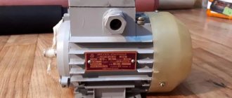
Convert a 380 volt electric boiler to 220?
Boiler EPO-1U3 7.5 kW 380 volts, 3-phase. Is it possible to convert it to 220 volts? The heating elements there are rented at 220.
08/17/2011 at 19:49
Now it is connected with a star. You put the same jumper at the bottom as at the top and it turns out to be 220, phase zero.
08/17/2011 at 19:50
Yes, converting to 220 is not a question; you close the TEN terminals in the same way as the upper contacts. The question is different - do you have an “extra” 7.5 kW in 1-phase for the boiler? And the cross-section of the wiring to the boiler will have to be changed to 3x6, or even 3x10.
08/17/2011 at 20:13
So there is still a lot of automation there, what should we do with it?
08/17/2011 at 20:38
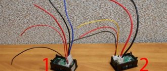
nervous wrote: ...you put the same jumper at the bottom as at the top and it turns out to be 220, phase zero.
There is no need to install any jumpers on the heating elements - just connect the red white and black cables to one phase terminal at the other end of the cable.
ZILBER wrote: So there is still a lot of automation there, what should we do with it?
There is no need to do anything with automation - that’s what automation is for, so that it can work without outside interference. The coils, I think, are all 220V.
08/17/2011 at 20:44
avmal wrote: it is enough to connect red white and black to one phase terminal at the other end of the cable.
- everything would be fine, only three times the current would flow through the zero wire. As if it wouldn't burn.
08/17/2011 at 20:51
alexposter wrote: three times the current will flow through the zero core
There is such a thing, but I overlooked it. Now 4x2.5 fits there. The only thing left to do, if it is not possible to replace the cable, is to distribute two wires between phase and neutral.
08/17/2011 at 20:57
Connect ABC, but connect only one of the heating elements - will it work like that?
08/17/2011 at 21:13
ZILBER wrote: if only one of the heating elements is connected, will it work like that?
- Are you willing to freeze all winter? By the way, what is the allocated power per house?
08/17/2011 at 21:20
- Are you willing to freeze all winter? By the way, what is the allocated power per house?
I have a lot of 7.5, although the power is limited only by the F4mm connection wires. So, did I understand correctly - close terminals A, B and C - phase is on them, and zero is on N?
08/17/2011 at 21:32
I installed it with someone I knew, changed all the wires inside the boiler to a normal cross-section of 6 squares, stretched out everything that was there, put a 5*4 cable out of the boiler and led it to a 3-pole 3*16 circuit breaker, which has jumpers on top. The steps (heating elements) are adjusted on the boiler itself so it’s convenient. I also added an external sensor, but that’s off topic.
Remaking chargers and more
08/17/2011 at 23:28
Judging by the connection, the heaters are 220V. 3 phases - for stepwise power control. Isn't this the connection diagram?
08/17/2011 at 23:47
avmal wrote: There is no need to install any jumpers on the heating elements - just connect the red white and black cables to one phase terminal at the other end of the cable.
the terminal is liquid a-lya-russ, there is one wire that will barely hold on. And you have three at once. It is better to replace the wire from the boiler.
quite possible. It’s also likely that the starter costs no more than the second value, plus the phase-by-phase power wiring inside the automation unit is not designed for single-phase connection of all three heaters at once, these are the weak points of the circuit in the case of connecting three heaters to one phase, if you don’t take this into account you might catch fire. in any case, you need to get inside the automation unit, study the device, and you also need to know the original circuit diagram from the boiler
08/18/2011 at 00:49
Why then is the N conductor connected to the midpoint?
08/18/2011 at 09:21
iyri wrote: Why then is the N conductor connected to the midpoint?
Well, at the midpoint there will be zero current only with all three voltages turned on, and in the three-phase version. If the automation turns on one heater, where will we put the current? In general, the TOE textbook will help you.
08/18/2011 at 11:04
ArVicBor wrote: If the automation turns on one heater
I doubt that she can turn on separate heaters in an atomizer. Judging by the buttons on the box, the heaters are apparently turned on separately manually, or through separate relays powered by buttons, or there is a starter that turns on the heaters selected by the user, and the heaters themselves are switched directly by the switch, although they look like they are for this is rather weak, you will still need to dig up the power part in the automation unit, strengthening it by tripling the load per phase.
08/18/2011 at 14:07 08/18/2011 at 15:10
Maybe everything is much simpler and leave only one heater on, perhaps it will be enough for your needs?
08/18/2011 at 17:03
what is the area of the room?
Remaking chargers and more
08/18/2011 at 20:02
One heating element is enough for me - the rest are spare. Just one question - where to apply 220 volts if I cut off the jumpers (bare wire) on the heating elements coming from the blue wire? (photo at the beginning of the topic) Here is a photo of the automation.
08/18/2011 at 20:49
ZILBER wrote: where to apply 220 volts if I cut off the jumpers (bare wire) on the heating elements coming from the blue wire?
No need to cut anything. Why do you have such a thirst for destruction? Simply connect the neutral to terminal N, and the phase wire to terminal A (photo 2).
08/18/2011 at 20:54
His blue one is already sitting on N. Look at which of these starters is triggered and remove the voltage from them.
08/18/2011 at 21:08
I doubt it very much, 2500 watts is not enough. Yes, you don’t need to cut anything. As I expected, each ten has its own dependency
in the second photo, on the input terminal you can see that on the terminals called N and A, in addition to the thick power wires, you can also see thin ones (blue and red), this is apparently the power supply for the automation circuit and one heater, these are the terminals that are connected to power the boiler phase with zero in accordance with the names. I think in this case the automation and one of the three heaters will work. And on the boiler itself, do not turn off or cut anything. One of the three heaters should turn on. and to power all the heaters, I think you need to put a jumper on the input terminal between the three phases (ABC) and apply only one phase to it, leaving zero N as is. In this case, it should be possible to power three heaters or two or one, depending from the position of the keys on the body
08/18/2011 at 22:02
Here's what else there is:
08/18/2011 at 22:28
All the advice has already been given - nothing new will appear.
08/18/2011 at 22:37
Well, that’s right, according to the diagram, this option is suitable for powering one heater and automation
nervous wrote: on the input terminal you can see that on the terminals called N and A, in addition to thick power wires, you can also see thin ones (blue and red), this is apparently the power supply for the automation circuit and one heater, so connect the phase to these terminals to power the boiler with zero in accordance with the names. I think in this case the automation and one of the three heaters will work. And on the boiler itself, do not turn off or cut anything. One of the three heaters should turn on
and if you need to power more than one tena, you will need to do this
nervous wrote: but to power all the tens, I think it is necessary to put a jumper on the input terminal between the three phases (ABC) and apply only one phase to it, leaving zero N as is. In this case, it should be possible to power three tens or two or one ,depending on the position of the keys on the body
08/18/2011 at 22:53
nervous wrote: in this case it should be possible to power three tens or two or one, depending on the position of the keys on the case
08/18/2011 at 23:59
I wrote about this almost at the very beginning how to do it
Remaking chargers and more
08/19/2011 at 00:00
So what? Do you want to say that it’s too thick for such a terminal? But this is a small mechanical problem, throw jumpers and also insert the six there. By the way, I’m in my councils, I noticed a small jamb. If you connect three tena using an interphase jumper at the input terminal, you will have to strengthen the neutral core. Three tena, the original zero will not work
08/19/2011 at 00:03
Anat78 wrote: I wrote about this almost at the very beginning how to do it
By the way, yes. then it is better to make a jumper on the input three-pole circuit breaker, and from it thinner to the terminal. The only thing is to strengthen the zero in the boiler circuit and that’s it
08/19/2011 at 10:52
Thank you all for such extensive help. I’ll do everything as you said - I’ll assemble it, take a photo, show it to you and only then turn it on.
09/18/2011 at 14:10
Hello. A problem arose when converting 380 to 220. Please tell me what was done wrong. Boiler 9 kW at 380V. I connected it to 220V, 6 kW - two heating elements of 3 kW each (put a jumper on A and B at the entrance to the boiler), one heating element is not powered. A wire with a cross section of 4 mm2, copper, single-core, is laid from the boiler to the switchboard.
In general, the story is like this. When one 3 kW heating element is turned on, everything works fine. When you turn on two, 6 kW, after 10 minutes the wire from the boiler to the network gets very hot. I made a mistake on the neutral wire in the boiler, replaced it with 10mm2, as a result, in the boiler, both the phase and neutral wires do not heat up (before the replacement, the neutral wire was heated), the terminals are cold, the “male and female” connector is cold, the wire to the switchboard still gets hot. What is the error 4mm2=6kW? Should I put a larger section? How long?
09/18/2011 at 15:43
DV1, are you sure that the heaters are 3 kW? Is the boiler body grounded or zeroed? The cable of the four should be enough for 6 kW. maybe you have a breakdown of the heating element on the boiler body, which could increase power consumption until the heating element burns out
09/18/2011 at 15:58
Yes, the heating elements are 3 kW each, the body is not grounded. How can you check the heating element in the simplest way (if possible)? PS I turned on both heating elements separately and they work fine, the wires do not get hot. Another question is that the neutral wire is connected by all three heating elements, although only two are connected, can it somehow affect the heating of the wires?
09/18/2011 at 18:10
DV1 wrote: Another question is that the neutral wire is connected by all three heating elements, although only two are connected, it can somehow influence the heating of the wires
Your question already has the answer. Of course not. if there was a phase without a zero on ten, then in this case it would be possible to develop a chain of events and relationships.
DV1 wrote: How can you check the heating element in the simplest way (if possible)?
Ring the ten tester on its body. Are you sure of the wire sections? There is a small difference between 2.5 squares and 4 squares. It can be confused. By the way, just yesterday I dealt with a wire of 2.5 and 4 squares. I feel like the one with 2.5 squares is significantly stiffer than 4.
09/18/2011 at 18:12
DV1 wrote: Yes, the heating elements are 3 kW each, the body is not grounded
but it is included in the heating system, it can also sit on zero ground.
09/18/2011 at 21:34
The body tester showed nothing. I bought wires specifically for the boiler only from the store, if they didn’t deceive me there, then exactly 4 squares. The thought has already arisen: maybe we need to put 6 squares?
09/18/2011 at 21:51
Do you have anything to measure the current consumption?
09/18/2011 at 22:04
DV1 wrote: Yes, the heating elements are 3 kW each, the housing is not grounded.
What “voltage” is written on the “tubular electric heater”?
DV1 wrote: The thought has already arisen, maybe we should put 6 squares?
First you need to find out the reason for the heating of the four squares, which should not exist given the parameters you specified.
09/18/2011 at 23:04
iyri wrote: Do you have anything to measure the current consumption?
No, there is only a multimeter up to 10A.
avmal wrote: What “voltage” is written on the “tubular electric heater”?
The boiler is EVPm-9, where the unit is of the TENB-P type 9 kW with a voltage of 220/380 V.
09/19/2011 at 00:36
DV1 wrote: No, there is only a multimeter up to 10A.
Can you supply 220V to terminals A and B through your device with a limit of 10A, disconnecting everything from the other terminals?
09.19.2011 at 06:31
avmal wrote: Can you supply 220V to terminals A and B through your device with a limit of 10A, disconnecting everything from the other terminals?
I can give it. It's just that I'm not good at electrical engineering. That's why I can't figure out how to do this? What to disable? What to measure? Should I apply specifically to A and B or A and N? Don’t kick me too hard, I really don’t understand it at all.
09.19.2011 at 10:11
avmal wrote: Can you supply 220V to terminals A and B through your device with a limit of 10A, disconnecting everything from the other terminals?
He most likely has a Ketai tester, and it measures 10 amperes only on a constant basis. So it will not be possible to measure the currents of the tens.
DV1, the person advises you, check the voltage for which the heaters are designed. It should be written on them. and measure the current by getting some commercial clamps somewhere, for 600 rubles you can buy passable ones. obvious overload although according to the description there should not be
09.19.2011 at 10:15
DV1 wrote: I can submit it. It's just that I'm not good at electrical engineering. That's why I can't figure out how to do this? What to disable? What to measure? Should I apply specifically to A and B or A and N? Don’t kick me too hard, I really don’t understand it at all.
what kind of tester do you have? what is written on the tester near the switch, in the section where there is a current measurement limit of 10 A? DCA?
09.19.2011 at 10:44
Chinese multimeter M832, DCA 10A. I can’t check (see) the voltage on the heating elements themselves. The heating elements are sealed into the boiler, only the threaded ends and about a centimeter of ceramics stick out. There is no information on the heating elements in the passport, as well as an electrical diagram. On the website of the boiler manufacturer it is written that they produce 9 kW TENB-P units with a voltage of 220/380 V. Therefore, they probably put them in the boiler.
I would like to try to connect the phase to C and alternately place the jumper CA and CB, maybe there will be some result. Does the heater work (heat) when it breaks through to the body? I noted the heating time to 70 degrees. On one shade it heats up in 40 seconds, on the other in 65 seconds.
09.19.2011 at 12:29
how hot it gets, maybe you’re panicking in vain?
DV1 wrote: Does the heater work (heat) when there is a breakdown on the case?
depending on how it pierces the body, if it is closer to zero and the boiler body is grounded to zero, then the power of the pierced tenon will increase, but in the end it will quickly burn out if there is crude protection against overcurrent at the input or a spiral is squeezed out of the rotten tenon and it begins to contact the boiler body .
DV1 wrote: I can’t check (see) the voltage on the heating elements themselves. The heating elements are sealed into the boiler, only the threaded ends and about a centimeter of ceramics stick out.
everything can be taken apart and seen; if the boiler is not new, it wouldn’t hurt to still disassemble it and inspect the condition of the insides.
DV1 wrote: I want to try to connect the phase to C and alternately place the jumper CA and CB, maybe there will be some result.
if there is a result, then in this way you will simply identify and exclude from the circuit a conditionally faulty or unsuitable voltage element.
DV1 wrote: I noted the heating time to 70 degrees. On one shade it heats up in 40 seconds, on the other in 65 seconds.
I would like to walk around with pliers and measure the currents. disassemble the boiler and inspect everything inside and look at the nominal values of the heaters.
You can connect one heater directly and connect the other two in series, I think the same power will be enough for you. but first you still need to inspect the internal contents of the boiler to see if there are prerequisites for an accident, breakdown, burnout, look at the ratings of the heaters
09.19.2011 at 20:51
nervous wrote: are you sure about the wire sections? There is a small difference between 2.5 squares and 4 squares. It can be confused. By the way, just yesterday I dealt with a wire of 2.5 and 4 squares. I feel like the one with 2.5 squares is significantly stiffer than 4.
I followed your advice. Armed with a caliper and measured the diameters of the wires (I bought several in the same store), the following was revealed: on the VVG label 2x4mm2 - in real life the diameter is 1.9mm, we count 3.14*1.9*1.9/4=2.83mm2 1x4mm2 - diameter 2mm, (3.14x2x2/4)=3.14mm2 PVA 2x6mm2 - diameter 2.4mm, (3.14*2.4*2.4/4)=4.52mm2 1x10mm2-diameter 3.6mm, ( 3.14x3.6x3.6/4)=10.1mm2 I installed a VVG wire with a diameter of 2x4mm2 on the boiler, the cross-section is 2.83mm2 - could this cause the wire to heat up? When the heat is strong, the insulation becomes soft in your hands.
Thanks for the answers and support.
PS Next time I'll go buy wires with a rod.
09.19.2011 at 21:28
DV1 wrote: I installed a VVG wire with a diameter of 2x4mm2 on the boiler, the cross-section is 2.83mm2 - could this cause the wire to heat up?
If everything is calculated correctly, then your wire with a cross-section of 2.83 mmkV should withstand your load without heating up, a wire with a cross-section of 2.5 is 6 kilowatts, and yours is even a little larger. So it shouldn’t get hot.
DV1 wrote: Strong heating causes the insulation to melt softly in your hands.
disassemble the boiler, look at what’s inside. what kind of heaters, what voltage and power. and find the current clamps, measure the current consumption of each tenon.
if you don’t want to disassemble the boiler, then try switching the heaters, suddenly one of them is of higher power or inappropriate voltage and you will identify it, no matter how funny it sounds, but by heating the wire. in any case, the boiler must be disassembled so that there are no surprises after you put it into operation
09.20.2011 at 21:02
Good evening Everyone, it’s me again, with my boiler, asking for your help. In general, I tried to turn on the heating elements alternately in different pairs, the result was negative, the wires also got hot. I didn’t like the wires in the boiler, they were all twisted into a ball, I took everything apart, replaced it (there was oxidized copper here and there), tightened it, cleaned it - they still got hot. I removed the male-female connector in front of the panel and threw another piece of wire from the boiler into the panel directly at the RCD (VD1-63, 50A). All the same, the wire is heating up, but since I left it open, I was able to touch it all and noticed that the heating starts from the RCD and it is the neutral wire that heats up. When the insulation almost melts near the RCD, the wire is barely warm near the boiler. The wires on the other side of the shield also heat up, but not so much. What can be wrong?
INSTALLING A COMBINED OVEN AND HOB OUTLET
The delivery set of the Prima combined socket includes the socket mechanism itself, a support - a mounting platform and a bolt.
First of all, you need to fix the support on the wall, next to the power cable for the stove, as shown in the image below.
Quite often, the wall where the electrical outlet for the stove in the kitchen is located is concrete or brick, so first we apply the support to the installation site and mark the mounting holes.
Then, using a hammer drill, in the marked places we make holes for fasteners; usually a drill with a diameter of 6 mm is used for this.
We fasten the support to the wall with dowel nails. You can also use any other suitable fasteners, for example, dowels (plugs) and self-tapping screws. If the wall material is soft, such as wood or foam block, it is not necessary to make holes; you can fix the support directly with self-tapping screws.
Let's disassemble the socket mechanism. To do this, you need to unscrew the bolt on the front side (see image below)
As you can see, inside there are two separate, unconnected mechanisms, one is a 16A “Euro” socket, and the other is a 32A power socket for a hob or stove. We will connect them a little later, but now we need to secure the socket mechanism in the support, on the wall.
For this purpose, the caliper has a special “eye,” and the platform where the sockets are installed has a protrusion that fits into this “ear.”
Then you need to tighten the bolts that are located in the places where the sockets are attached to the platform. These bolts pass through the mechanism and are screwed into the caliper, where threaded mounting holes are specially made for them, thereby reliably connecting the caliper with the mechanisms.
Before proceeding directly to the connection, be sure to make sure that there is no voltage on the input power cable. You can turn off the current supply in the electrical panel; most often, it is enough to simply find the appropriate machine; it is usually of the largest nominal value, most often 32A-40A.
For your convenience, below we have prepared a diagram that clearly shows the order of connecting the wires.
Carrying out installation work
The main thing when performing electrical installation work is compliance with safety rules. Always operate with the power switched off.
Connecting the plug and socket
To connect the plug, strip the wire from the oven or stove; if the wire is stranded, then crimp it with NShV lugs and pass it through the plug body. Mount the phase and neutral on the outermost contacts of the plug. Yellow-green grounding conductor - on the middle contact. To prevent the wire from dangling inside the plug, clamp it with a clamp and tighten the plug body.
The socket is connected in the following way: the socket is mounted in the required place, the socket body is removed and the power line is connected to it. Mount the phase and neutral on the outermost contacts of the socket. Yellow-green grounding conductor - on the middle contact. Next, screw the socket housing.
Cable connection diagrams for the oven and hob
There are two main circuits for connecting an electric stove or hob: single-phase and three-phase. The connection is made to the terminals of the hob, which can be accessed through its back cover - it is unscrewed and removed. Pay close attention to the color markings on the terminals - this will allow you to avoid mistakes, read the connection instructions and safety requirements.
Single-phase 220V circuit (most common in apartments)
Phase L is simultaneously connected to terminals L1-3 of the hob. To do this, two removable copper jumpers are installed between them at the manufacturer. If for some reason you don’t have jumpers, you can make them yourself from an electrical cable whose cross-section is no less than that of the supply cable. Zero N is connected to terminals N1-2. Protective conductor PE – to the PE terminal.
Three-phase 380V circuit (common in private homes and businesses)
Phases A, B, C – are connected to terminals L1-3 of the hob. In this case, it is necessary to remove the jumpers installed at the factory between terminals L1-3. Zero N is connected to terminals N1-2. Protective conductor PE – to the PE terminal.
Connecting the oven is much easier. Most often, such devices are already supplied with an electrical cord with a plug for connection, so the Euro plug is simply inserted into a Euro socket. To connect to machines or terminals, it is best to use a separate cable, since if you cut off the plug on the cable from the kit, this can significantly affect the warranty for this device.
The oven connection diagram is always single-phase:
- Phase L is connected to terminal L of the oven;
- Zero N is connected to terminal N;
- Protective conductor PE – to the PE terminal.
How to convert an electric stove socket from 380 volts to 220? Stove Lysva EP-31
What wires should be routed and where? I'm looking for something on the Internet and can't find a sensible answer anywhere.
Added 5 years ago
The socket-plug is round, with 3 wires. The old stove was standing, it had an ordinary plug - converted, just one brown wire was insulated. I want to do the same thing, but I don’t know, do I need to change anything in the stove itself?
Vote for best answer
If it is a household electric oven, it cannot operate on 380 V; all household ovens operate on 220 V. Maybe you mean that it has a large round plug with 3 large pins? This is a 220V plug for high power electrical appliances. There is no point in replacing it with a regular one - it will simply melt. You need to replace the socket with a similar one. It’s simple - the side sockets are phase/zero, the middle one is grounding. For reliability, you can disassemble the plug of the panel - the ground wire is always green and white. And it is advisable to have a separate wire from the panel to the stove, otherwise the plugs will be knocked out.
great greatStudent (102) 5 years ago
he asks about the OUTLET of the electric stove. like there is a 380 socket on the stove, but he wants to plug a 220-volt load into it.
chapenkov11 Sage (10145) I answered as I understood. Let the author decide whether it is correct or not.
TUNINGProfi (667) 5 years ago
Thanks for the helpful hint, I still need to find out if something needs to be done in the stove itself? Yes, I stepped a little, about 380 volts and sockets. 3 wires - round plug..
chapenkov11 Sage (10145) There is no need for a stove, just connect the socket correctly.
When asking a question, you need to at least explain in detail what you want to do. where is the so-called socket or what do you call the terminal block in the stove, people begin to guess and guess and are unable to answer the question that interests you
This outlet is already 220 volts. the three contacts there are: phase zero ground. if the outlet had 3 phases and 380 volts, then there would be 4 contacts.
Preparatory stage
Now let's move on to the preparation and subsequent connection of the equipment in question. Before you start directly connecting and working with electrical wiring, you should choose the right place for the stove. There are the following rules on how to do this:
- the place where you plan to install the stove must be level, so that when adjusting with the legs, its stable and stable horizontal position is ensured;
- the length of the wire should be made with a reserve so that, if necessary, you can easily move the household appliance away from the wall without removing the plug from the socket;
- In no case should the device be placed close to the refrigerator, since the hot burner can have a temperature of up to hundreds of degrees;
- if the stove is built into a kitchen wall or cabinet, then the panels made of plastic should be protected from overheating during operation of the electrical appliance;
- It is better not to place other electrical appliances near an induction cooker - the electromagnetic field can negatively affect their operation.
To carry out the work you will need to have the following materials on hand:
- 3-core cable, the cross-section of which will be 4-6 millimeters. This will depend on the length;
- a separate machine for the panel in order to correctly connect the equipment. There should be either a 32-amp version or a 40-amp equivalent, depending on the wire cross-section;
- RCD, which should protect equipment from overloads.
The last two points are considered mandatory components of the process of connecting the device in question, regardless of the manufacturer. They are the ones who will save equipment from burning out due to voltage surges that can be observed in the city’s electrical network. It's kind of a switch. If the builders carried out only a 3-core wire, then to install a special socket or terminal box you will need to make channels in the wall to deepen the cable. This work will require some skills and will take a lot of time, but in the end the interior of the room will not be damaged, and the cable will be located inside the wall. True, you first need to decide what would be best to do:
- connect everything directly;
- install a socket;
- install the transfer case.
If you don't know what to choose, you should consult a professional. Connecting directly is considered the safest, because the absence of unnecessary cables significantly reduces the risk of device overheating. In new high-rise buildings the situation is simplest - the builders simply leave the cable insulated, and the residents decide for themselves what to do. The solution through the terminal box, if there is no plug on the cable, is also possible in new houses.
The box is usually placed on the kitchen wall no lower than 0.6 meters from the floor, and the stove is installed no further than a couple of meters from it. As a rule, it is made of metal or very durable plastic, and is covered with a lid on top.
It should be noted that there is already a connection to the home electrical network inside. You just need to find out how to connect the electric stove. The circuit is very simple: the black cable represents the phase, the blue cable represents the neutral, and the yellow cable represents the ground. All 3 wires are connected to the box, oriented by color. Then all that remains is to check the tightness of the connection screws and close the cover.
Another way to connect is through an outlet. There are currently three categories of sockets on the market:
Belarusian;
In the Russian version, the ground wire is located on top, its input is rotated 90 degrees to 2 other holes. When working with a Belarusian socket, the contacts are rotated 120 degrees. A feature of the European socket is the presence of two contacts with a round cross-section, and the grounding will have a flat cross-section and be located at the bottom. But this option is considered obsolete. If there is no point in creating wiring, then the mounted socket simply needs to be checked with a special device to find out the phase.
Selecting a connection type
There are three main types of connections with which you can operate an electric stove. Each of them can be used in private houses and apartments, in country houses.
Direct connection
This option is the safest, because in the absence of additional cables, the risk that the equipment will overheat is reduced. In new buildings, builders solve such issues very simply: they do not install boxes, but simply insulate the cable.
Direct connection diagram
Via terminal box
New apartments have dispensers installed in the kitchens at a level of at least 60 cm from the floor surface. The device should be mounted no further than two meters from it. Terminal boxes are made from high-quality metal or durable plastic.
This part is already connected to the home electrical network; all that remains is to connect the equipment. The scheme is simple and does not require special skills. There are three colored wires inside the block:
- black - phase;
- blue - zero;
- yellow - grounding.
Wire designation
The wires must be connected to the block in accordance with the color scheme. It is simply impossible to make a mistake in such a scheme.
You should carefully check the tightness of the connecting screws, and then close the lid.
Through a socket
The next type of connecting electrical appliances to the network is the installation of a specially configured socket with mandatory grounding.
Today, there are three main types of sockets used in the kitchen.
- Russian design with an upper ground wire, its input is rotated 90° to the other two holes.
- Made in the Republic of Belarus - here all contacts are rotated 120°.
- The European type has two round contacts, and the grounding is flat and located at the bottom of the device. This is an outdated option, because now many countries have switched to their own types of outlets.
If there is no need to do wiring, then the installed socket in the kitchen should be checked with a special device to determine the phase.
Cable installation
When choosing the cross-section of an underwater cable, many make the mistake of being guided only by data on the maximum current consumed by the electric stove. Ignoring the fact that the cable must withstand a current greater than the rating of the circuit breaker in the panel.
As a cable for connecting household electric stoves, it is most rational to use a flame retardant cable with single-wire copper conductors, for example, VVGng or NYM.
The cable for the electric stove should be installed together with the rest of the wiring in a hidden way. It should come out of the wall near the installation site of the electric stove.
Grounding an electric stove
An electric stove must be grounded. All work in houses is divided into 2 categories:
- the presence of a common grounding circuit;
- lack of a grounding loop.
In the first case, you will need a copper flexible wire with a cross-section of at least 2.5 mm2, which must be laid from the electrical panel and connected to the stove body. In the second case, installing an RCD, performing grounding (using a protective neutral conductor) or both methods together will help.
Where there is no centralized gas supply, an electric stove is a necessary kitchen device and its operation and service life depend on how it is connected
When choosing a cable or wire, you need to choose the right brand, wire cross-section and quantity, and also pay attention to the manufacturer of this product. And do not forget that electric current is a source of increased danger, leading to undesirable consequences.
Therefore, it is better to entrust the installation of an electric stove to specialists who know all the intricacies of such a connection, and are also well versed in the necessary materials, accessories, fixtures and know how to use control and measuring equipment.
How to connect the power cable yourself
So, we have chosen a way to connect our primary kitchen devices. But our power cables are connected conditionally. Let's find out how to do it for real. Traditionally, we will consider separately the oven and hob.
For an oven (with a power of no more than 3.5 kW, P = 3.5 kW), you need to purchase a piece of PVA cable 3*2.5 and a regular 16A household plug. The length of the cable must be such that after connection the cable is not strained
When connecting to a plug (let's agree that the cable has brown, blue and yellow wires), it is important to connect the yellow (yellow-green) wire to the ground terminal. The order of connecting the phase and zero is as follows: the brown wire is the phase, the blue wire is zero
In a socket, the phase can be determined using a phase indicator (any household appliance does not respond to the phase-zero order - if the TV plug is inserted opposite the current position, the TV will still work, however, it will be better to follow the operating conditions of this electrical appliance). Next, remove the small plastic cover at the cable connection point.
There we will see the connection for each cable core.
The connection is made as follows: L is phase, N is zero, the earth sign is yellow (yellow-green are the colors of earth from an electrical point of view) according to the colors of the cores
Very important: the colors of the wire cores in the plug with a ground-phase-zero combination must correspond to a similar combination in the connected device. If the phase in the plug is the brown wire of the cable, then in the oven it is the brown wire
Exactly the same with zero and earth - purely by color.
Cooking surface. As a rule, hob models are universal. This means connecting to both 220V and 380V. The transition to both one and the other voltage is realized by installing the appropriate jumpers. On most hobs, at the point where the power cable is connected (a conveniently accessible plastic cover), you can see a similar connection diagram:
In the case of an apartment, where the allocated voltage is 220V, the output is obvious (in the case of a private house, with a allocated 380V, electricians adapt the power output to the hob to 220V).
In order for the hob to operate on 220 V, jumpers must be installed according to line 3 of the connection diagram. For a voltage of 380V, select line 1. In practice it might look like this:
Or like this:
As for the power cable, it is better to use PVS 3*6 (except for the case when the cable in the socket has a smaller cross-section - which is 3*4mm2). In any case, it is recommended to adhere to the principle - the cross-section of the power cable cannot be less than the cross-section of the cable in the socket (the wire protruding from the wall to connect the hob). It can do more. As mentioned above, the hob is a large consumer of electricity. With a power of 7.3 kW (P=7.3kW), it is necessary to install a socket and plug designed for a current of 32A.
The combination of colors of cable cores with ground, phase and zero is completely similar to the case of an oven.
When connecting the power cables of the oven and hob, the brand of PVA cable was indicated. PVA is a flexible multi-core power cable in PVC insulation. But with a permanent connection to an electrical wiring cable (and this is in most cases a VVG-ng cable with monolithic inflexible cores), it would be more effective to use a cable of a similar brand. From the point of view of ease of connection, it is possible. From the point of view of operation, we are still dealing with household appliances, and they have some mobility. A monolithic cable is designed to be stationary; there is a possibility of core breakage, but not great. The probability of breakage of the connection points inside the device is already higher. Therefore, multicore cable (MCC) is more convenient in this case.
When performing work on electrical equipment, strictly follow safety precautions against electric shock.
How to properly ground an electric stove
An improperly grounded electric stove is dangerous. There may be high voltage on its body. It is invisible until a current circuit passes through the user's body. For example, when touching the body of the stove with one hand and the battery with the other. Of course, the surfaces of all modern electrical appliances are covered with enamel or powder coating with the addition of plastic. But this does not mean that you can ignore the connection rules.
In outdated electrical networks, this is often done by connecting the apartment zero point to the grounding contact. This is fraught with the occurrence of emergency situations. When this line burns out in the panel, high voltage will be supplied to the device.
It is even more dangerous when inexperienced electricians take over on networks where the cables are not color-coded. In this case, the phase and zero often change places. This “grounding” immediately forms a high voltage on the plate body. Electric shock can occur to a person at any time.
There are several options for grounding a household stove. Which one to choose – everyone decides individually.
What you should never do
Among some ordinary people there is an opinion that central heating pipes made of metal will be an excellent point for connecting the ground. This option should not be used under any circumstances. Connecting the ground terminal to the battery pipe creates a danger for all residents of the house.
There are cases where people received an electric shock. There are also fatal accidents; the neighbors below the careless owner of the electric stove received serious electrical injuries. Even if the device is on the ground floor and the current path does not pose an obvious danger, the water inside the pipes is a conductor. And the risk of electric shock to home residents remains quite high.
Research of the apartment panel
You can find out whether the apartment panel or the common one on the staircase is grounded from the company servicing the house or from the housing office. If they cannot give a definite answer, it is better to find another way to solve the problem. But if the user receives accurate data, preferably documented data, it is enough to drill a hole in the metal bus of the shield and screw a bolt into it. By attaching the yellow-green wire of the plate to it, the latter is safely grounded.
Creating a Ground Loop
The rules for grounding real estate are subject to strict standards, which describe both the design of the bus and its resistance and other parameters. However, for domestic conditions when protecting the slab, the system can be simplified. To create a grounding loop, proceed as follows.
- Three metal rods with a diameter of 16 mm or more and a length of 250 mm or more are driven into the ground along the wall of the house at a distance of half a meter to a meter from each other. Alternatively, you can use steel corners.
- A grounding loop is created by welding a steel strip 40-50 mm wide and 5 mm thick to the free ends of the rods (corners).
- An 8 mm steel wire is led from the contour along the wall. At one end it is welded to the strip, at the other it has a plate with a hole for a bolt.
- The wire is brought out to the level of the apartment window.
- From the inside, along the floor or above, the grounding cable for the stove is led out.
- The wire is connected to the plate using a bolt at a height of at least 250 mm from the ground.
The circuit you made yourself must be checked. To do this, it is worth inviting a regional power grid specialist. The household circuit must have a resistance of no more than 8 ohms. If this parameter is larger, you will need to drive in additional rods. The optimal value of the ground loop is 4 ohms and below.
Passive protection
What to do if you can’t ground the stove? In this case, preventive measures against electric shock are applied.
- The stove is placed so that it is impossible to simultaneously touch its body and taps, radiators, and other metal objects.
- A dielectric coating is laid on the floor near the stove, in the work area. This is rubber, linoleum, at least a dense dry rug.
- Circuit breakers with thermal releases are replaced with differential ones. The latter react to leakage currents of 30 mA and will quickly break the circuit if an emergency occurs.
A dielectric mat will protect you from electric shock.
Naturally, the stove should be handled extremely carefully. Lack of grounding threatens not only the health of the device owner. The stove itself can become a source, for example, of a fire, causing significant material damage.
Protective grounding and RCD selection
The metal body of the stove must be grounded: connected with a separate conductor to the ground loop.
For residents of cottages or private houses for which this contour has already been completed, this point will not cause difficulties. In their input or distribution panel there is a PE bus, to which only wires and cable cores with yellow-green colors are suitable.
For residents of private houses that do not have such a circuit, the time has come to think about the need to finally make one. The fact is that the heating elements of electric stoves operate in extreme conditions. Despite the fact that their insulation is designed for operating temperature, the most common occurrence when they fail is the appearance of a phase potential on the housing.
And other elements of the stove: switches, electrical wiring, terminal blocks - run the risk of being flooded with water when cooking. Contacts can theoretically burn out, and burnt wires can fall onto parts connected to the housing. If the protection does not work in such a situation, the person using the stove will suffer.
A ground loop is the best way out of the situation. But where can residents of apartment buildings get it? There is an opinion that the housing of the distribution panel in the entrance is definitely connected to the ground loop. You should not rely on this, since it is not connected to the circuit, but to the combined neutral conductor of the network. And if it breaks, a phase may appear on this body.
No one will let you bury your own circuit in the yard: communications run underground. What's the solution? Do not connect the housing to anything, additionally protecting the electric stove with a residual current device (RCD).
If an RCD is used, if the insulation is damaged, an instant shutdown will not occur. It will happen if you touch the body of the electric stove. The current will flow through your body, but will be turned off so quickly that there will be no threat to health.
The operating current of the RCD is selected equal to or greater than the current of the circuit breaker installed to protect the stove. RCD differential current – 30 mA. You can combine the functions of the machine and the RCD by installing one element - a differential machine.
Selecting a circuit breaker
If the electric stove's passport does not indicate the rated current of the circuit breaker, then it can be determined independently by its rated current. It is better to find out its exact value from the plate, since sometimes manufacturers issue instructions for the entire model range, which have different capacities. If the plate indicates power (P), then it will need to be converted into current. For a single-phase electric stove:
For three-phase:
Do not forget that power is substituted in the formulas in watts, and not in the kilowatts indicated on the plate.
The circuit breaker must be selected for a rated current greater than the calculated value. Depending on which network the electric stove is connected to: single-phase or three-phase, choose a single-pole or three-pole switch.
Connection procedure
In principle, the owner can decide for himself how to lay the cable (in a groove on the wall, under a plinth or cladding). From the author’s point of view, it is not worth reminding that you must first unscrew the fasteners on the cover under which the terminal block is located, turn off the voltage in the panel when installing the socket, and the like. But some diagrams will be useful, and there is practically no need for comments on them.
Direct cable connection is indicated both in the documentation and on the contact panel of the electric stove, with explanatory symbols.
What to consider:
- For single-phase connection, terminals 1, 2 and 3 are connected by jumpers. They must be in a bag with accessories (included in delivery). The same applies to the zero terminals (4 and 5). The picture shows everything well.
- If jumpers are missing, they are easy to make. But only from the wire that connects the electric stove to the network! If you take a smaller cross-section, then it is not a fact that they will withstand.
The process of connecting an electric cooking surface
If the consumer decides to connect complex and powerful household appliances to the power supply network with his own hands, then he must have basic knowledge in the field of electrical installation work. Otherwise, to avoid negative consequences, you should invite a specialist. Therefore, we will not describe what tools need to be used when connecting an electric hob and provide step-by-step instructions for installation work. We will also assume that the power cable with grounding has already been laid to the installation site of the device. So let's get started! Let's start by installing the power outlet.
Power socket
Selecting and installing a power socket and plug is the most important part of the entire process of connecting powerful household appliances. The plug connection must be able to withstand the maximum possible current consumption. The design and other features of the socket and plug do not matter. For a single-phase network, the power socket and plug have three contacts, and for a three-phase network, five. The following figure shows both types of plug connections for connecting powerful household appliances.
Installation of a power socket and plug is carried out according to the general rules for electrical installation work. The main thing is to observe the polarity of the connection and not to confuse the phases with neutral conductors and grounding. If you are unsure which of the conductors is phase and which is neutral and ground, you need to use an indicator screwdriver or a multimeter. After installing the power socket and connecting the hob cable to the plug, it is necessary to perform certain manipulations in the terminal box of the device. This is the subject of the next section of the article.
Connection terminals
For different models of hobs, the terminal boxes may have different designs, but all of them are necessarily equipped with contacts for connecting the following conductors of the power cable.
- Phase terminals for connecting power supply L1, L2 and L3.
- Contact for connecting the working neutral conductor N.
- Terminal for connecting protective grounding PE.
As mentioned above, to connect panels to a single-phase network, it is necessary to install special jumpers on the phase contacts. For a two-phase network, one jumper is installed. The two neutral conductors are bridged for any connection. The figure below shows a diagram for installing jumpers for all types of electrical networks.
Most often, jumpers are included in the delivery of hobs.
It is important to install them correctly and not mix up the contacts. Otherwise, a short circuit may occur or the panel simply will not work. The bottom photo shows the most common connection option inside the hob terminal box for single-phase electrical wiring
The bottom photo shows the most common connection option inside the hob terminal box for single-phase electrical wiring.
Before performing manipulations with the device connection terminals, you should study the instructions for connecting the purchased equipment. The body of most hob models also contains a detailed connection diagram, type of terminals and location of jumpers for different connection options. This will allow you to avoid basic mistakes when connecting panels, which we will discuss below.
Selecting a circuit breaker
Before connecting a new electric stove, oven or powerful hob, examine the general condition of the electrical wiring and check for the presence of an automatic safety switch (circuit breaker).
When connecting a single-phase stove, an automatic switch is installed on the line, designed for a current of 32 A. Such a switch is installed if the rated current of the input switch is 40-50 A.
After installing the machine, a residual current device (RCD) is connected in series, with a rated current of 32-40 A and a differential current of up to 30 mA. Instead of a machine and an RCD, it is permissible to install a difavtomat that combines the functions of both devices.
For a three-phase connection, a three-pole circuit breaker is installed, designed for a rated current of 16A, and a four-pole RCD is installed for 25 A rated current and 30 mA differential.
Main selection criteria
In order to choose the right introductory machine (VA), you need to know what characteristics you should pay attention to when purchasing
Rated current
This is the most important characteristic when choosing an input protective device. This property of the device indicates the maximum current, if exceeded, the power will be turned off within a certain time.
Regardless of whether the machine is introductory or provides protection for a specific line (wire), its calculation is made based on the maximum power of electricity consumers. The rating of the input device is selected by calculating the power (or current) of all consumers when simultaneously connected to the network, for greater safety, reducing the resulting number by 10-15%, rounding down to a lower value.
Number of poles
There are machines with different numbers of poles. Single-pole ones are used to protect individual lines. The functions of the input circuit breaker are usually performed by two, three or four-pole circuit breakers.
An important rule that will help you choose the number of poles is that for single-phase networks, two-pole circuit breakers are used, and for three-phase networks, three or four-port circuit breakers are used. Two-pole switches are made with a lever and a shutdown mechanism common to both poles
That is, in an emergency, two poles are disconnected at once (usually a phase is connected to one terminal, and zero to the second). Such devices are often used in single-phase networks of residential premises of apartment buildings
Two-pole switches are made with a lever and a shutdown mechanism common to both poles. That is, in an emergency, two poles are disconnected at once (usually a phase is connected to one terminal, and zero to the second). Such devices are often used in single-phase networks of residential premises of apartment buildings.
A three-pole (or four-pole) machine is used when introducing electrical cables into private houses with a three-phase network, as well as in industrial buildings and even in some apartments. A phase is connected to each terminal of the device (and zero if it is a four-terminal network). It, like a two-terminal switch, has one common lever for all poles and, in case of overload, turns off the power in all phases.
Time-current characteristic
It characterizes the instantaneous tripping current and is most often indicated on the device by the Latin letters B, C or D. The sensitivity of the protective device to inrush currents of electrical appliances and equipment depends on the time-current characteristics. For an input circuit breaker, this property is important, since it affects the operation of lower groups of circuit breakers.
The following types of machines are most often used based on their time-current characteristics:
- B – at a current value 3 - 5 times higher than the rated value, the electromagnetic switch of the device will operate and it will instantly turn off;
- C – the electromagnetic release will turn off the device when the current exceeds 5-10 times;
- D – will work when the current exceeds 10-20 times the rated current.
For the input circuit breaker in residential premises, devices with a time-current characteristic of type C are used, since most devices in the home do not have large starting currents and will not have a negative impact on the electrical network of the apartment or house.
The response characteristics of each device are indicated in the passport and instructions of the circuit breaker manufacturer.
Mounting method
All circuit breakers have a standard mounting and are placed on a DIN rail in the electrical panel. The same rule applies to introductory machines. The exception is special devices for industrial purposes, which can be mounted without a DIN rail on special fasteners.
Switch brand
When choosing an input protective switch, as well as in the case of choosing any electrical devices, it is important to focus on a well-known manufacturer that has earned recognition. Such manufacturers provide a quality guarantee for their devices and produce reliable, durable and safe circuit breakers
The most popular machines today include machines from the following manufacturers:
Electrical installation kit
To connect the equipment to the electrical network, you will need to prepare:
- cable for laying the line;
- circuit breaker;
- socket;
- fork;
- flexible wire.
All installation equipment is selected depending on the power of the VP. Having it at your disposal, you can begin direct electrical installation. Additionally, you may need crimp sleeves, solder, electrical tape, heat-shrink tubing and other small items used when working with electrical wiring. Also, depending on the chosen connection method, you will need a socket box or junction box.
Requirements for electrical wiring and its installation
To turn on a built-in electric stove, you need to use a cable coming directly from the electrical panel
That is, it is important that it be laid directly without the use of junction boxes with branches. It is necessary that the cable only powers the hob
The fact is that such equipment is very powerful, so if other equipment operates from the wire, it may overheat, causing a short circuit.
Wire 5 cores for 3-phase network
If the house or apartment has old wiring, and there is no powerful socket with a direct cable from the panel or meter, then you will need to lay a new separate line. From the desired location of the outlet, a vertical groove is made to the ceiling. Next, horizontal grooves are carried out directly to the cable connection point. If you plan to use suspended ceilings in the future, then the wire can be fixed directly to the floor slab, since in the future it will be hidden.
The line for the electric stove is laid using 2 types of cables: VVGng-Ls or NYM. Their throughput is selected based on the power of the built-in equipment.
Table 1. The ratio of the cross-section of the cores and the power of the hob.
| power, kWt | Core cross-section, mm2 | |
| 1-phase network | 3-phase network | |
| 3-5 | 2,5 | 1,5 |
| 5-7,5 | 4 | 2,5 |
| 7,5-10 | 6 | 2,5 |
These types of cable are used to lay lines directly to the outlet. They consist of a monocore, so they have little flexibility. For this reason, flexible wires are used directly from the plug to the hob: KG or PVA. They are often included as standard with the electric stove, so there is no need to purchase them separately.
Flexible extension cord
Selecting an outlet and requirements for its installation
The socket for turning on the panel can be located depending on the features of the tabletop, as well as personal preferences
It is important to maintain the convenience of turning the hob on and off. As a standard, it is placed at a height of 90 cm from the floor.
If you want to hide communications, you can fix the socket directly below the bottom of the lower kitchen cabinets. With this placement, access to it is provided through the space created by the height of the legs of the bedside tables. It should be raised above the floor to a height of at least a few centimeters so that in the event of a leak, the electrical contacts do not get wet.
Socket under the cabinet
Connecting the hob through an outlet, rather than directly to the panel, has its advantages. Although you will have to do a more complicated installation, it will be easier to turn it off in the future when you wet clean the stove. If you connect without a socket and plug, you will need to go to the electrical panel, which is not so convenient.
The 2-burner stove can be powered through a regular outlet. More powerful equipment requires special switches. They can be made of ceramic or plastic. Sockets from 10A are used.
Selecting a circuit breaker
The line for connecting the built-in electric stove must be laid through a circuit breaker. This is a mandatory requirement since the slab can create network overload. At critical loads, the switch will prevent short circuits
It is very important to choose it correctly, in accordance with the power of the stove. If the cable itself for the panel can be used more powerful, then the circuit breaker must fully comply with it
You should not save on purchasing it, since cheap devices often do not work or turn off even when the stove is operating in normal mode with a low load.
Prices for automatic machines
Difavtomat
Standard shield machine
Table 2. Correspondence of the current of the machine to the power of the stove.
| Circuit breaker current, A | Circuit power | |
| 220V | 360V | |
| 5 | 1.1 | 2.6 |
| 6 | 1.3 | 3.2 |
| 8 | 1.7 | 5.1 |
| 10 | 2.2 | 5.3 |
| 16 | 3.5 | 8.4 |
| 20 | 4.4 | 10.5 |
| 25 | 5.5 | 13.2 |
| 32 | 7 | 16.8 |
| 40 | 8.8 | 21.1 |
conclusions
A modern electric stove is quite complex equipment. In order for an electric stove to operate with maximum safety and efficiency, it is necessary to provide it with power with the appropriate parameters. The socket, wiring and circuit breaker must withstand a load greater than that created by the stove itself. It is best if a separate line is used to power the stove, and appropriate devices are used to protect it. Only an experienced specialist can correctly connect the stove to the electrical network in compliance with all necessary requirements. It’s not worth doing this on your own, especially if you don’t have the skills. Installing wiring yourself can cause a lot of trouble.
Independent connection of an electric stove to a 220 V, 380 V network
Electricity is a serious and dangerous matter, but many jobs do not require high qualifications and can be done independently without the involvement of specialists. For example, you can connect an electric stove with only a vague understanding of electricity. Especially if the outlet is already installed. All that remains is to install a plug on the cord and connect it correctly to the connectors of the stove. The situation is worse if it is necessary to pull the line from the shield, but even here you can cope without help. Just remember that all work is carried out with the power supply turned off.
Conclusions and useful video on the topic
Detailed video about installing a power outlet in an overhead way and connecting the power plug to an electric stove:
A visual video of connecting the cable to an electric stove according to the diagram provided by the manufacturer:
Video about connecting an electric stove to a power outlet with a plug left over from an old stove:
You can connect a power outlet without involving electricians. To do this, you need to choose the right device, taking into account the power of the equipment that will be turned on. The main thing is to lay a separate cable specifically for the stove and secure it by installing a circuit breaker and an RCD. The installation process itself is no different from installing a regular outlet.