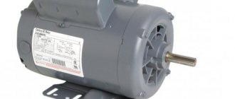
The reliability, uninterrupted operation and ease of maintenance of a three-phase asynchronous electric motor have been tested by time, millions of users around the world and do not require proof. Moreover, it is the most widespread, accessible and cheapest today. However, not everyone has a 380 V current source. Therefore, let’s look at what it means to connect a three-phase electric motor to a 220 V network, what methods exist for this and what are their main features.
Three-phase electric motor Source ytimg.com
Winding connection options
An asynchronous three-phase electric motor has three windings - for each phase separately - going into the stator slots. However, for the generation of electromotive force and, as a result, rotation of the rotor, they must be connected to each other. It is important to know the connection option for a specific motor. Since this will help you choose the right scheme for connecting it to the 220V network.
Each of the three windings corresponds to its own phase and has both a beginning and an end. In this case, the inputs and outputs are designated by the corresponding letters and numbers:
Range of engines produced during the Soviet Union:
- The first phase is C1-C4.
- Second phase C2-C5.
- Third phase C3-C6.
Designations of modern engines:
- First phase U1-U2.
- Second phase V1-V2.
- Third phase W1-W2.
Connecting the winding of a three-phase motor Source autogear.ru
There are two main circuits for connecting the windings in the type of motor under consideration:
- Star.
All winding outputs are connected to one point, and the inputs, respectively, to the phases. The schematic representation of this method looks like a star. With this method, a 220V phase is applied to each individual core, and a linear 380V is applied to two consecutive cores.
The main advantage of this scheme is the application of linear current to two wires simultaneously, which significantly reduces inrush currents and allows the rotor to perform a soft start. The downside is lower power due to weak currents in the winding.
- Triangle.
The input of the previous winding is connected to the output of the next one - and so on in a circle. As a result, the diagram resembles a triangle. At a linear voltage of 380V, the currents in the winding will reach a significantly higher value than in the above option. This will make it possible for the motor to exert a significantly greater amount of force. The disadvantage of the circuit is that stronger inrush currents can lead to network overload.
Triangle diagram Source ytimg.com
Good to know! To obtain the advantages of the first and avoid the disadvantages of the second circuit, the connection of the 380 V electric motor and its subsequent acceleration is carried out on the “star”, and then it is automatically switched to the “delta”.
Connecting a three-phase motor to a single-phase network
The rotor connected to the three-phase circuit of a three-phase motor rotates due to the magnetic field created by the current flowing at different times through different windings. But, when such a motor is connected to a single-phase circuit, no torque arises that could rotate the rotor. The simplest way to connect three-phase motors to a single-phase circuit is to connect its third contact through a phase-shifting capacitor.
When connected to a single-phase network, such a motor has the same rotation speed as when operating from a three-phase network. But the same cannot be said about power: its losses are significant and they depend on the capacity of the phase-shifting capacitor, the operating conditions of the motor, and the selected connection diagram. Losses approximately reach 30-50%.
The circuits can be two-, three-, or six-phase, but the most commonly used are three-phase. A three-phase circuit is understood as a set of electrical circuits with the same frequency of sinusoidal EMF, which differ in phase, but are created by a common energy source.
If the load in the phases is the same, the circuit is symmetrical. For three-phase asymmetrical circuits it is different. The total power consists of the active power of the three-phase circuit and the reactive power.
Although most motors cope with operation from a single-phase network, not all can work well. Better than others in this sense are asynchronous motors, which are designed for a voltage of 380/220 V (the first is for star, the second is for delta).
This operating voltage is always indicated in the passport and on the plate attached to the engine. It also shows the connection diagram and options for changing it.
If "A" is present, this indicates that either a delta or star circuit can be used. “B” indicates that the windings are connected in a “star” and cannot be connected in any other way.
The result should be: when the contacts of the winding with the battery are broken, an electric potential of the same polarity (i.e., the arrow deflects in the same direction) should appear on the two remaining windings. The start (A1, B1, C1) and end (A2, B2, C2) terminals are marked and connected according to the diagram.
Definition of connection diagram
Before choosing one or another scheme for connecting a motor to 220 V, it is necessary to determine what the connection diagram for its winding is and at what rating it can generally be operated. To do this you need:
- Find and study the technical table on the engine. characteristics .
The information field contains all the important information - designation of the type of connection ∆ - triangle or star - Y , power, number of revolutions, voltage (220 or 380, or 220/380) and the possibility of connecting according to a specific circuit.
- Open the terminal box and verify in practice that the assembled circuit is correct.
The beginning and end of each winding is signed in accordance with the above alphanumeric nomenclature. The user remains to study the connection diagram using jumpers: according to what scheme the connection is made - star or triangle.
Note! If the nameplate (table with information) indicates the Y and only 380V, then when it is connected in a triangle, the winding will burn out. Only professional electricians can upgrade such a 220V motor. Therefore, there is no reason to modify it, especially since today there are many copies that can operate alternatively - both 220 and 380 volts.
Opening the terminal box Source pikabu.ru
See also: Catalog of companies that specialize in electrical work
Reversing the engine
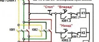
In order to make the motor rotate in the other direction, it is enough to “reverse” the phase arriving at the connection point of windings B and C (Triangle connection) or to winding B (Star circuit). The circuit, which allows you to change the direction of rotation of the rotor by simply clicking the SB2 switch, will look like this.
Reversing a 380 V three-phase motor operating on a single-phase network
It should be noted here that almost any three-phase motor is reversible, but you need to select the direction of rotation of the motor before starting it. It is impossible to reverse the electric motor while it is running! First you need to de-energize the electric motor, wait for it to stop completely, select the desired direction of rotation with the SB1 toggle switch, and only then apply voltage to the circuit and briefly press button B1.
Connection methods for 220V
To connect a three-phase asynchronous electric motor to a 220-volt network, there are several proven methods:
- With capacitor.
- Without capacitor.
- With reverse.
- Combined star-delta circuit.
Let's look at them in more detail.
Important! When connecting a 380-volt electric motor to a 220-volt network, you need to be prepared to reduce its power to 70% of the factory value. However, in everyday conditions this is quite acceptable and will not affect the performance in any way.
Connecting a 380 V motor to 220 V Source ytimg.com
With capacitor
The most popular and affordable way to initiate 380 volt motors from a 220 V network is a circuit using a capacitor. Its role is to create a phase shift in the windings relative to each other in order to form a rotating magnetic field. If there are three phases, this phenomenon occurs by itself - only one will not force the rotor to rotate. Therefore, the optimal method for connecting an electric motor with 4 wires on one phase is to use a starting winding, in addition to the main winding, in 220V electric motors.
For the 380 V modification, two connection options with a capacitor are possible:
- With working capacitor Cp .
- And parallel connected working Cp and starting capacitor Sp .
In the second case, the engine starts more smoothly and safely. Sp module turns on for a short period of time and turns off as the rotor reaches the required speed. The choice of starting option is largely determined by the degree of rotor load during starting. So, if the start occurs without force, only Cp , and if under load, without free rotation, the presence of Cn .
Connecting a motor with capacitors Source blogspot.com
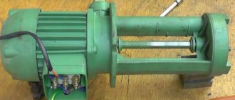
Three-phase asynchronous motor: what to pay attention to before connecting it
With a few exceptions, we get the asynchronous machine in an unknown state. Very rarely does it have an inspection certificate and a certified warranty from an electrical laboratory.
Even in this case, I recommend making sure it works personally.
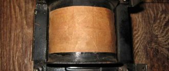
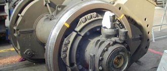
Mechanical condition of the stator and rotor: what can interfere with engine operation
The fixed stator consists of three parts: a middle housing and two side covers, secured with studs. Pay attention to the gap between them and the tightening force with the nuts.
The body must be tightly compressed. A rotor rotates inside it on bearings. Try turning it by hand. Evaluate the force applied: how the bearings work, whether there are any beats.
Without proper experience, minor defects cannot be detected in this way, but a case of severe jamming will immediately appear. Listen to the noises: is there any contact with the stator elements by the rotor when rotating?
After turning the engine to idle and running for a short time, listen again to the sounds of rotating parts.
Ideally, it is better to disassemble the stator, visually assess its condition, wash the dirty rotor bearings and completely replace their lubricant.
Electrical characteristics of stator windings: how to check the assembly circuit
The manufacturer indicates all the main parameters of the electric motor on a special plate attached to the stator housing.
You can trust these factory specifications only if you are sure that after the factory, none of the electricians changed the winding connection diagram or made involuntary mistakes. And I came across such cases.
And the sign itself may become erased or lost over time. Therefore, I propose to understand the technology of rotor spin-up.
To understand the electrical processes occurring inside the motor stator, it is convenient to imagine it in the form of an ordinary toroidal transformer, when three equal windings are symmetrically located on the ring core of the magnetic circuit.
The stator circuit is assembled inside a closed housing, from which only six ends of the windings are removed.
They are marked and connected on a terminal block covered with a lid for assembly according to a star or delta circuit using a standard rearrangement of jumpers.
The right side of the picture shows the assembly of the triangle. I publish the jumper arrangement diagram for the star below.
Electrical methods for checking winding assembly circuits
But not everything is as simple as it might seem at first glance. There are a number of engines that deviate from these rules.
For example, a manufacturer may produce electric motors not for universal use, but for operation in specific conditions with the windings connected in a star configuration.
In this case, he can assemble the three ends of the windings inside the stator housing, and bring out only four wires for connection to the phase and zero potentials.
Installation of these ends is usually performed in the area of the back cover. To switch the windings to a triangle, you will need to open the housing and make additional conclusions.
It's not a difficult job. But it requires careful handling of the varnish coating of the copper wire. When the wire is bent, it may be damaged, which will lead to a breakdown of the insulation and create an interturn short circuit.
After rewiring the circuit, I recommend additionally coating the outer layers of the windings with varnish, and then drying them thoroughly with warm air before final assembly.
What to do if there are no pin markings
On an old asynchronous motor, the wires may be removed from the terminals, and the factory markings may be lost. There were also instances where six ends simply stuck out from the body. They need to be called and labeled.
We carry out the work in two stages:
- We check that the ends belong to the windings.
- We identify and label each pin.
At the first stage, we use a multimeter or tester in ohmmeter mode. We place the first probe randomly on one terminal, and with the second, we look for the one from the five remaining wires where the device will show a shorted circuit. We mark both ends as belonging to the same winding.
We proceed in the same way with the remaining four conclusions. As a result, we get three pairs of wires from each winding.
How to find the end and beginning of a winding: 2 ways
You can search using a voltmeter:
- and batteries;
- or a reduced AC voltage source.
The first method is based on the fact that a current pulse applied to one of the three windings is transformed into the other two.
To do this, connect the negative battery to a randomly selected end of K1, and briefly touch the second terminal with the positive contact. A pulsed inrush current passes through the circuit and induces an EMF in the other two windings.
Using a DC voltmeter, the polarity of the induced voltage in each winding is checked by the deflection of the arrow. The beginning is marked with the terminal that corresponds to the positive potential (the arrow of the device moves to the right when the battery is closed and to the left when the circuit is opened by the battery).
After marking the ends, I recommend checking the correctness of their application by applying a pulse to another winding.
The second method is based on the use of an alternating voltage source of a safe value of 12-36 volts.
The ends of any two windings are connected in parallel and a voltmeter is connected to them. An alternating voltage is applied to the remaining third winding and the reading of the device is looked at.
If the induced EMF corresponds to the applied voltage, then these two windings are connected in the same polarity. Their beginnings and ends are marked equally. If the voltmeter reading is zero, the ends of one of the windings must be unscrewed and the measurement taken again.
Then one of the marked windings, for example No. 3, is connected to the first and a voltmeter is connected to them. The vacated No. 2 is again supplied with alternating voltage. The polarity of the terminals is determined by the magnitude of the EMF on the voltmeter.
After marking is completed, a control measurement is taken to check the work performed.
When there is no step-down transformer or safe power supply at hand, an experienced electrician with the right to independently work under voltage can use an ordinary 60-watt incandescent lamp.
It is used as a voltage divider, connected in series to one winding of the electric motor. 220 volts are supplied to the assembled chain, and the voltage is measured on the other two with a voltmeter.
This kind of testing is dangerous. This should not be done by untrained people: you can easily get an electrical injury.
How to assess the condition of winding insulation
Some bloggers are silent about the need for this check. They believe that they can do without it in most cases.
However, before energizing the engine, I recommend:
- take a megohmmeter with an output voltage of 1000 volts;
- check the insulation between each individual winding and the housing, as well as between all windings;
- if it is higher than 0.5 MΩ, then consider the starter to be in good condition. Otherwise you will have to repair it. Drying with dry and warm air often helps.
Checking the insulation of the electric motor with a megohmmeter must be carried out before connecting it to load. However, it is not able to detect damage to the dielectric layer that causes interturn short circuits in the winding.
When assembling the engine, each stator coil is wound with copper wire of the same length and cross-section. Therefore, they all have exactly the same resistive resistance.
If an interturn short circuit occurs in the winding, then, as a rule, it can be determined by measuring a multimeter in ohmmeter mode. To do this, carefully analyze and compare the active resistance of each chain.
How to check the stator magnetic field at the factory
When voltage is applied to a working electric motor, a rotating magnetic field is created. It is visually assessed using a metal ball that repeats the rotation.
I do not encourage you to repeat such an experience. This example is intended to help you understand that the operation of an asynchronous motor is based on the interaction of the magnetic fields of the stator and rotor.
Only the correct connection of the windings ensures the rotation of the ball or rotor.
Motor power and winding wire diameter
These are two interrelated quantities because the cross-section of the conductor is selected based on its ability to withstand heating from the current flowing through it.
The thicker the wire, the more power can be transmitted through it with acceptable heating.
If there is no plate on the engine, then its power can be judged by two signs:
- The diameter of the winding wire.
- Dimensions of the magnetic core.
After opening the stator cover, analyze them visually.
Useful tips
Some useful tips on how to connect a 3-wire motor to avoid problems during operation:
- Before starting work, it is recommended to test the engine at idle, if it is functioning properly, then under load.
- If the case becomes very hot, even without load, it is necessary to reduce the capacity of the working capacitor.
- If after starting the motor just hums, but does not rotate the shaft, then you can set it to start manually - by turning the shaft. Next, you can increase the capacity of the starting capacitor.
- When stopping the engine under operating load, the capacity of the working capacitor should be increased.
Helpful information! It is possible to correctly calculate the capacitance of the capacitor only taking into account the power rating of the motor. If there is underload, overheating will occur and the capacity will need to be reduced.
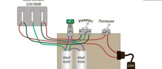
How to change the direction of rotation
If you need to change the direction only once, then this can be done at the rework stage. To do this, it is enough to swap any two stator windings. The same goal is achieved by transferring a branch of capacitors from zero to phase, or vice versa. But if you need to frequently reverse a three-phase converted motor, a switch is needed. By assembling the electric motor according to the diagram below, you will free yourself from changing the windings every time you need to set the direction of rotation of the shaft in the opposite direction.
There is nothing difficult about converting a three-phase electric motor to a single-phase network with your own hands. The greatest difficulty will be only the calculation of the capacitance of the working capacitor and the experimental selection of the capacitance from the calculated range for the starting accumulator. But this becomes easy if you haven’t lost your technical passport and have a calculator at hand.
More on the topic: - Connection diagrams for asynchronous and synchronous single-phase motors - Connection diagrams for an electric motor via capacitors - Reversible diagram for connecting an electric motor - Do-it-yourself soft start of an electric motor - What is the difference between asynchronous and synchronous motors - Reversible connection of a single-phase asynchronous motor with your own hands - How to check an electric motor - Electric motor repair
Briefly about the main thing
You can connect a 380 to 220 volt electric motor in 4 main ways:
- With capacitor.
- Without capacitor.
- With reverse.
- Star-delta design.
Before starting connection work, it is necessary to determine and verify how the winding is connected in the terminal box, and also find out the necessary characteristics from the technical table. You can perform electrical work if you have experience, but it is better to entrust it to professionals with the appropriate permit.
Using a magnetic starter
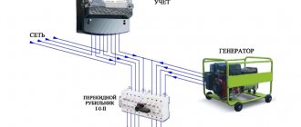
The good thing about using a 380 electric motor connection diagram is that it can be started remotely. The advantage of a starter over a switch (or other device) is that the starter can be placed in a cabinet, and the controls can be placed in the work area; the voltage and currents are minimal, therefore, the wires are suitable for a smaller cross-section.
In addition, connection using a starter ensures safety in the event that the voltage “disappears,” since this opens the power contacts, and when the voltage appears again, the starter will not supply it to the equipment without pressing the start button.
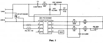
Connection diagram for a 380V electric asynchronous motor starter:
At contacts 1,2,3 and start button 1 (open), voltage is present at the initial moment. Then it is supplied through the closed contacts of this button (when you press “Start”) to the contacts of the coil starter K2, closing it. The coil creates a magnetic field, the core is attracted, the contacts of the starter close, driving the motor.
At the same time, the NO contact closes, from which the phase is supplied to the coil through the “Stop” button. It turns out that when the “Start” button is released, the coil circuit remains closed, as do the power contacts.
By pressing “Stop”, the circuit is broken, returning the power contacts to open. The voltage disappears from the conductors and NO supplying the engine.
Video: Connecting an asynchronous motor. Determination of engine type.
If you have a three-phase electric motor, you know it doesn't come cheap. Therefore, if you need to use a single-phase motor, the thought of buying new equipment will only come to you when you do not know how to make an electric motor at home. We will tell you how to convert an electric motor from 380 to 220 Volts with your own hands.
Efficiency
Unfortunately, a three-phase motor, when powered by one phase, will not be able to develop its rated power. Why? In normal mode, each of the motor windings develops a power of 33.3%. When the motor is turned on, for example, in a “triangle” mode, only one winding C operates in normal mode, and at the point of connection of windings B and C, with a correctly selected capacitor, the voltage will be 2 times lower than the supply voltage, which means the power of these windings will drop 4 times - only 8.325% each. Let's do a simple calculation and calculate the total power:
33,3 + 8,325 + 8,325 = 49.95%.
So, even theoretically, a three-phase motor connected to a single-phase network develops only half of its rated power, and in practice this figure is even less.
Capacitances of phase-shifting and starting capacitors
To calculate the capacity of a phase-shifting capacitor, you need to use a simple formula:
- C1 = 2800/(I/U) - for inclusion according to the “Star” circuit;
- C1 = 4800/(I/U) - for switching on according to the “Triangle” scheme.
Here:
- C1 is the capacity of the phase-shifting capacitor, μF;
- I is the rated current of one motor winding, A;
- U is the voltage of a single-phase network, V.
But what to do if the rated current of the windings is unknown? It can be easily calculated by knowing the motor power, which is usually printed on the device nameplate. To calculate we use the formula:
I = P/1.73*U*n*cosф, where:
- I—current consumption, A;
- U—mains voltage, V;
- n - efficiency;
- cosф - power factor.
The symbol * denotes the multiplication sign.
The capacity of the starting capacitor C2 is selected 1.5–2 times greater than the capacity of the phase-shifting one.
When calculating a phase-shifting capacitor, you need to keep in mind that an engine operating at less than full load may overheat at the design capacitor capacity. In this case, its denomination must be reduced.
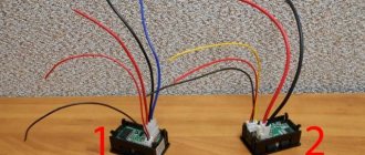
How to distinguish a reversing starter from a direct one
A reversing starter is a more complex device. In fact, it consists of two conventional direct starters, the latter combined in one housing. The internal circuitry of the reversing device is characterized by the fact that it is impossible to run two modes at the same time - direct and reverse. This process is controlled by a blocking circuit, which can be electrical or mechanical.