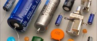
A capacitor is a passive electronic component that has two poles with a fixed or variable capacitance value. It also has low conductivity. It is important to understand what a capacitor is for in an electric motor and car, because according to the information provided on forums, many people have the wrong idea about this and simply underestimate the importance of this device.
What is a capacitor used for?
The device is used in all electrical and radio circuits. For what purposes is a capacitor included in the circuit:
- Acts as a resistance, which allows it to be used as a filter to suppress high-frequency and low-frequency interference.
- They are used for photo flashes and lasers, and all thanks to the device’s ability to accumulate charge and quickly discharge, creating a pulse.
- Helps compensate for reactive energy, allowing it to be used in industry.
- Thanks to the ability to accumulate and retain charge for a long time, a capacitor can be used to store information and power low-power devices.
What is a car capacitor used for?
This device can perform several functions in the car. For example, they are used to create high voltage levels throughout the entire electrical system in a car. Most often, a capacitor is used for car acoustics. Speaking about why condensates are needed in car audio, we note that its main purpose is to help the amplifier quickly deliver the available power at low frequency peaks.
If a capacitor is not used in the speaker system, then the bass sound will not be as clear, and there may also be a drawdown in the power supply to the entire electrical network of the car. Such power surges can ultimately lead to the subwoofer simply breaking down.
When choosing a capacitor for a car, follow the rule that there should be 1 F per 1 kW of power. Choose high-quality capacitors and it is best if they have charge control capabilities.
It's also worth figuring out how to properly install the capacitor. It is best to do this as close as possible to the subwoofer amplifier, since this is where the heaviest load is placed. The distance should not be more than 60 cm. Connection type – parallel.
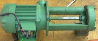
Why is a capacitor needed in an electric motor?
For some motors to operate properly, it is necessary to use a starting and running capacitor. The main purpose of the starting capacitor is to improve the starting performance of the engine. This device helps reduce the time it takes for the engine to enter its operating mode, while increasing torque and facilitating the engine starting process.
As for the working capacitor, it is involved in work throughout the entire operating time of the engine. This device ensures the heating of the windings permissible by standards, optimal load capacity and efficiency of the electric motor. It also contributes to maximum torque and increased engine life.
Now you need to find out which capacitor is needed for the motor. The capacitance of this device is usually selected on the basis that there should be 6.6 mF per 100 W. Sometimes this value is incorrect, so it is best to select the capacity through experimentation. There are several selection methods, but the most accurate values can be obtained by connecting the motor through an ammeter. It is important to control the current consumption at different capacities. The task is to find at what capacitance the current value on the ammeter will be minimal.
If there is a need to connect an asynchronous three-phase electric motor to a household network, you may encounter a problem - it seems completely impossible to do this. But if you know the basics of electrical engineering, you can connect a capacitor to start an electric motor in a single-phase network. But there are also capacitorless connection options; they are also worth considering when designing an installation with an electric motor.
Simple ways to connect an electric motor
The easiest way is to connect the motor using a frequency converter. There are models of these devices that convert single-phase voltage to three-phase. The advantage of this method is obvious - there is no power loss in the electric motor. But the cost of such a frequency converter is quite high - the cheapest copy will cost 5-7 thousand rubles.
There is another method that is used less frequently - the use of a three-phase asynchronous winding to convert voltage. In this case, the entire structure will be much larger and more massive. Therefore, it will be easier to calculate which capacitors are needed to start the electric motor and install them by connecting them according to the diagram. The main thing is not to lose power, since the operation of the mechanism will be much worse.
Read also: Drawings for turning
Connecting a single-phase electric motor: using a magnetic starter
But there is another way - connecting a single-phase electric motor as a generator to produce three-phase voltage.
The magnetic field of the main winding maintains rotation for a long time. The solution is to install a 3-pole switch. This procedure is implemented by simply changing the order in which the starting winding is turned on when it is connected to the working winding. This is due to the fact that when only the working winding C1-C2 is connected to the network, a single-phase capacitor motor will have a pulsating magnetic field rather than a rotating one, that is, it will not start. It is necessary to connect chokes to each of the network wires to eliminate interference.
The magnetic circuit of single-phase motors contains a two-phase winding, consisting of a main winding and a starting winding. Control of starting current indicators in such motors is carried out by a frequency converter. This will be one of the network wires. The most convenient is a magnetic starter controlled from alternating current. All containers included in the circuit must be of the same type.
If after this the engine turns out to be hot, then: The bearings may be dirty, jammed, or simply worn out. The idea of using a starting capacitor is to include it in the circuit only at the moment the motor starts. Machines for processing raw materials, etc. Connecting a capacitor. How to connect a capacitor to an electric motor. Scheme.
Features of the circuit with capacitors
The windings of all three-phase electric motors can be connected according to two schemes:
- “Star” - in this case, the ends of all windings are connected at one point. And the beginnings of the windings are connected to the supply network.
- “Triangle” - the beginning of the winding is connected to the end of the adjacent one. The result is that the connection points of the two windings are connected to the power supply.
The choice of circuit depends on what voltage the motor is supplied with. Typically, when connected to a 380 V AC network, the windings are connected in a “star”, and when operating under a voltage of 220 V - in a “delta”.
In the picture above:
a) star connection diagram;
b) triangle connection diagram.
Since a single-phase network clearly lacks one supply wire, it needs to be made artificially. For this purpose, capacitors are used that shift the phase by 120 degrees. These are working capacitors; they are not enough when starting electric motors with a power of over 1500 W. To start powerful engines, you will need to additionally include another container, which will facilitate work during the start.
Connection
Calculating the values of their capacitances is relatively simple: for the working one 0.75 μF per 1 kW of power, for the starting one - 2.5 times more. Its structure is slightly different from a conventional single-phase asynchronous motor.
A circuit with a working, always-on capacitor works better in nominal mode, but has mediocre starting characteristics. The operating voltage of these capacitors should be 1.5 times higher than the network voltage, that is, for network B we take capacitors with an operating voltage of B and higher.
But despite this, they are widely used in the production of household appliances. These motors have lower efficiency values.
After assembling the electromagnetic starter circuit, you should connect the power section. Its structure is slightly different from a conventional single-phase asynchronous motor. Its power can range from five to ten kilowatts. In addition to the presence of two phases, it is required that one winding be shifted relative to the other by a certain angle.
We recommend: current volumes and standards of electrical equipment testing
Operating principle of a commutator motor
Starting scheme: Starting is carried out by a magnetic field, which rotates the moving part of the motor. Next example.
Single-phase asynchronous electric motors Design and principle of operation The power of such a single-phase motor B can, depending on the design, range from 5 W to 10 kW. On which of them there is no difference, the direction of rotation does not depend on it. Look at the photo and you can clearly see that the wire cross-sections are different. When connecting the device in question, several types of connections are made. That is, if the auxiliary winding of a single-phase motor is starting, its connection will occur only during the start-up, and if the auxiliary winding is a capacitor, then its connection will occur through a capacitor, which remains turned on during engine operation.
Connection diagram for a 220 Volt commutator motor
These electricity ratings are available in all residential premises in our country, and as a result, single-phase motors are extremely popular. We need an initial push. Current is supplied to the rotor windings through brushes in contact with the commutator plates, to which the ends of the rotor windings are connected. Connection diagram 2 Connecting an asynchronous single-phase electric motor to the network.
The function of the centrifugal switch is to cut off the starting phase when the rotor reaches its rated speed. Further rotation of the rotor is ensured by the pulsating magnetic field of the working phase, as already described in the previous paragraph. Two and three-phase motors It is possible to connect a 2 or 3-phase motor to a single-phase power source. how to connect a three-phase motor to a single-phase network
Working capacitor capacity
In order to find out what capacitors are needed to start an electric motor when operating on a 220 V network, you need to use the following formulas:
- When connected according to the “star” scheme, C (slave) = (2800 * I1) / U (network).
- When connected in a “triangle” C (slave) = (4800 * I1) / U (network).
Current I1 can be measured independently using clamps. But you can also use the following formula: I1 = P / (1.73 · U (network) · cosφ · η).
The value of power P, supply voltage, power factor cosφ, efficiency η can be found on the tag, which is riveted on the motor housing.
Start capacitor
In the event that the motor is subject to heavy loads or its power exceeds 1500 W, a phase shift alone cannot be done. You will need to know what other capacitors are needed to start an electric motor of 2.2 kW and higher. The starter is connected in parallel with the worker, but only it is excluded from the circuit when the idle speed is reached.
Be sure to turn off the starting capacitors - otherwise phase imbalance and overheating of the electric motor occurs. The starting capacitor should be 2.5-3 times larger in capacity than the working capacitor. If you consider that a capacitance of 80 μF is required for normal operation of the motor, then to start you need to connect another block of capacitors of 240 μF. You can hardly find capacitors with such a capacitance on sale, so you need to make a connection:
- When the capacitances are added in parallel, the operating voltage remains the same as indicated on the element.
- In a series connection, the voltages are added, and the total capacitance will be equal to C (total) = (C1*C2*..*CX)/(C1+C2+..+CX).
It is advisable to install starting capacitors on electric motors whose power is over 1 kW. It is better to reduce the power rating a little to increase the degree of reliability.
Basic parameters of capacitors
The capacitance of a capacitor characterizes the energy that the capacitor is capable of accumulating, as well as the current that it is capable of passing through itself. Measured in Farads with a multiplying prefix (nano, micro, etc.).
The most commonly used values for run and start capacitors range from 1 μF to 100 μF.
The rated voltage of a capacitor is the voltage at which the capacitor is able to operate reliably and for a long time, maintaining its parameters.
Well-known capacitor manufacturers indicate on its body the voltage and the corresponding guaranteed operating time in hours, for example:
- 400 V - 10,000 hours
- 450 V - 5000 hours
- 500 V - 1000 hours
What type of capacitors to use
Now you know how to select capacitors to start an electric motor when operating on a 220 V AC network. After calculating the capacitance, you can begin to select a specific type of element. It is recommended to use the same type of elements as working and starting elements. Paper capacitors perform well; their designations are as follows: MBGP, MPGO, MBGO, KBP. You can also use foreign elements that are installed in computer power supplies.
The operating voltage and capacitance must be indicated on the body of any capacitor. One drawback of paper cells is that they are large in size, so to operate a powerful engine you will need a rather large battery of cells. It is much better to use foreign capacitors, since they are smaller in size and have a larger capacity.
Operation of an electric motor without a capacitor
Thermal vacuum treatment increases the service life of the capacitor, eliminating the possibility of internal corrosion of the elements. Clean room, with humidity and air temperature control, high-performance Swiss equipment. We are ready to produce up to 20 pcs. Where other factories employ people, we have automated machines. Faster, better quality, more reliable. The presence of our own testing laboratories for all types of products allows us to provide additional guarantee to customers regarding the quality of our products.
Using Electrolytic Capacitors
You can even use electrolytic capacitors, but they have a peculiarity - they must operate on direct current. Therefore, to install them in the structure, you will need to use semiconductor diodes. It is undesirable to use electrolytic capacitors without them - they tend to explode.
But even if you install diodes and resistors, this cannot guarantee complete safety. If the semiconductor breaks through, then alternating current will flow to the capacitors, resulting in an explosion. The modern element base allows the use of high-quality products, for example, polypropylene capacitors for operation on alternating current with the designation SVV.
Read also: Do-it-yourself heating of the carbon dioxide reducer
For example, the designation of elements SVV60 indicates that the capacitor is designed in a cylindrical housing. But SVV61 has a rectangular body. These elements operate under a voltage of 400. 450 V. Therefore, they can be used without problems in the design of any device that requires connecting an asynchronous three-phase electric motor to a household network.
Single-phase electric motor with asymmetric stator magnetic circuit
Stator
Such a single-phase motor is made with pronounced poles on an asymmetrical laminated core. Rotor
— short-circuited “squirrel cage” type.
This electric motor does not require the use of phase-shifting elements to operate. The disadvantage of this engine is low efficiency.
A single-phase motor operates using alternating electric current and is connected to single-phase networks. The network must have a voltage of 220 Volts and a frequency of 50 Hertz.
Electric motors of this type are used mainly in low-power devices:
- Household appliances.
- Low power fans.
- Pumps.
- Machines for processing raw materials, etc.
Models are available with power from 5 W to 10 kW.
The values of efficiency, power and starting torque for single-phase motors are significantly lower than for three-phase devices of the same size. The overload capacity is also higher for 3-phase motors. Thus, the power of a single-phase mechanism does not exceed 70% of the power of a three-phase mechanism of the same size.
device
Device:
- It actually has 2 phases, but only one of them does the work, which is why the motor is called single-phase.
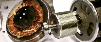
- Like all electric machines, a single-phase motor consists of 2 parts: stationary (stator) and moving (rotor).
- It is an asynchronous electric motor, the stationary component of which has one working winding, connected to a single-phase alternating current source.
The strengths of this type of engine include the simplicity of the design, which is a rotor with a squirrel-cage winding. The disadvantages are low starting torque and efficiency.
The main disadvantage of single-phase current is its inability to generate a magnetic field that performs rotation. Therefore, a single-phase electric motor will not start on its own when connected to the network.
In the theory of electrical machines, the rule applies: in order for a magnetic field to arise that rotates the rotor, there must be at least 2 windings (phases) on the stator. It is also required to shift one winding by a certain angle relative to the other.
During operation, alternating electric fields flow around the windings:
- In accordance with this, the so-called starting winding is located on the stationary section of the single-phase motor. It is shifted 90 degrees relative to the working winding.
- A current shift can be obtained by including a phase-shifting link in the circuit. Active resistors, inductors and capacitors can be used for this.
- 2212 electrical steel is used as the basis for the stator and rotor.
Operating voltage
One important parameter of capacitors must be taken into account - operating voltage. If you use capacitors to start an electric motor with a very large voltage reserve, this will lead to an increase in the dimensions of the structure. But if you use elements designed to operate with a lower voltage (for example, 160 V), this will lead to rapid failure. In order for capacitors to function normally, their operating voltage must be approximately 1.15 times greater than the network voltage.
Moreover, you need to take into account one feature - if you use paper capacitors, then when working in alternating current circuits their voltage must be reduced by 2 times. In other words, if the housing indicates that the element is designed for a voltage of 300 V, then this characteristic is relevant for direct current. Such an element can be used in an alternating current circuit with a voltage of no more than 150 V. Therefore, it is better to assemble batteries from paper capacitors, the total voltage of which is about 600 V.
Connecting a 3-phase motor to a household network
Table of contents
A simple way to turn on a three-phase motor.
1.1. Selecting a three-phase motor for connection to a single-phase network.
Among the various methods of starting three-phase electric motors in a single-phase network, the simplest is based on connecting the third winding through a phase-shifting capacitor.
The useful power developed by the engine in this case is 50.60% of its power in three-phase operation. Not all three-phase electric motors, however, work well when connected to a single-phase network. Among such electric motors we can highlight, for example, those with a double cage squirrel-cage rotor of the MA series. In this regard, when choosing three-phase electric motors for operation in a single-phase network, preference should be given to motors of the A, AO, AO2, APN, UAD, etc. series. For normal operation of an electric motor with capacitor starting, it is necessary that the capacitance of the capacitor used varies depending on the speed. In practice, this condition is quite difficult to fulfill, so two-stage motor control is used. When starting the engine, two capacitors are connected, and after acceleration, one capacitor is disconnected and only the working capacitor is left.
1.2. Calculation of parameters and elements of an electric motor.
If, for example, the electric motor’s data sheet indicates its supply voltage is 220/380, then the motor is connected to a single-phase network according to the diagram shown in Fig. 1
Rice. 1
Schematic diagram of connecting a three-phase electric motor to a 220 V network:
C p - working capacitor;
C p - starting capacitor;
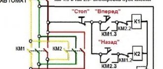
After turning on the batch switch P1, contacts P1.1 and P1.2 close, after which you must immediately press the “Acceleration” button. After gaining speed, the button is released. Reversing the electric motor is carried out by switching the phase on its winding with toggle switch SA1.
The capacity of the working capacitor Cp in the case of connecting the motor windings in a “triangle” is determined by the formula:
| , Where | Cp is the capacity of the working capacitor in μF; I is the current consumed by the electric motor in A; U - network voltage, V |
And in the case of connecting the motor windings in a “star”, it is determined by the formula:
| , Where | Cp is the capacity of the working capacitor in μF; I is the current consumed by the electric motor in A; U - network voltage, V |
The current consumed by the electric motor in the above formulas, with a known power of the electric motor, can be calculated from the following expression:
| , Where | P - engine power in W, indicated in its passport; h - efficiency; cos j—power factor; U - network voltage, V |
The capacity of the starting capacitor Sp is chosen 2..2.5 times greater than the capacity of the working capacitor. These capacitors must be designed for a voltage of 1.5 times the mains voltage. For a 220 V network, it is better to use capacitors such as MBGO, MBPG, MBGCh with an operating voltage of 500 V and higher. Subject to short-term switching on, electrolytic capacitors of the K50-3, EGC-M, KE-2 types with an operating voltage of at least 450 V can be used as starting capacitors. For greater reliability, electrolytic capacitors are connected in series, connecting their negative terminals together, and are shunted diodes (Fig. 2)
The total capacitance of the connected capacitors will be (C1+C2)/2.
In practice, the capacitance values of the working and starting capacitors are selected depending on the engine power according to the table. 1
Table 1. The value of the capacitances of the working and starting capacitors of a three-phase electric motor depending on its power when connected to a 220 V network.
| Three-phase motor power, kW | 0,4 | 0,6 | 0,8 | 1,1 | 1,5 | 2,2 |
| Minimum capacity of the working capacitor Cp, µF | 40 | 60 | 80 | 100 | 150 | 230 |
| Minimum starting capacitor capacity Ср, µF | 80 | 120 | 160 | 200 | 250 | 300 |
It should be noted that in an electric motor with capacitor starting in no-load mode, a current flows through the winding fed through the capacitor by 20.30% higher than the rated one. In this regard, if the engine is often used in underloaded mode or idling, then in this case the capacitance of the capacitor Cp should be reduced. It may happen that during an overload the electric motor stops, then to start it, the starting capacitor is connected again, removing the load altogether or reducing it to a minimum.
The capacity of the starting capacitor Cn can be reduced when starting electric motors at idle or with a light load. To turn on, for example, an AO2 electric motor with a power of 2.2 kW at 1420 rpm, you can use a working capacitor with a capacity of 230 μF, and a starting capacitor - 150 μF. In this case, the electric motor starts confidently with a small load on the shaft.
1.3. Portable universal unit for starting three-phase electric motors with a power of about 0.5 kW from a 220 V network.
To start electric motors of various series, with a power of about 0.5 kW, from a single-phase network without reversing, you can assemble a portable universal starting unit (Fig. 3)
When you press the SB1 button, the magnetic starter KM1 is triggered (toggle switch SA1 is closed) and its contact system KM 1.1, KM 1.2 connects the electric motor M1 to the 220 V network. At the same time, the third contact group KM 1.3 closes the SB1 button. After complete acceleration of the engine, turn off the starting capacitor C1 using toggle switch SA1. The engine is stopped by pressing the SB2 button.
1.3.1. Details.
The device uses an electric motor A471A4 (AO2-21-4) with a power of 0.55 kW at 1420 rpm and a magnetic starter of the PML type, designed for alternating current voltage of 220 V. Buttons SB1 and SB2 are paired type PKE612. Toggle switch T2-1 is used as switch SA1. In the device, the constant resistor R1 is wire-wound, type PE-20, and the resistor R2 is type MLT-2. Capacitors C1 and C2 type MBGCh for a voltage of 400 V. Capacitor C2 is made up of parallel connected capacitors of 20 μF 400 V. Lamp HL1 type KM-24 and 100 mA.
The starting device is mounted in a metal case measuring 170x140x50 mm (Fig. 4)
Rice. 4 Appearance of the starting device and drawing of the panel, pos. 7.
| 1- building | 2 — carrying handle | 3 - signal lamp | 4 - toggle switch to turn off the starting capacitor |
| 5 - “Start” and “Stop” buttons | 6 - modified electric plug | 7- panel with connector sockets |
On the top panel of the case there are “Start” and “Stop” buttons - a signal lamp and a toggle switch to turn off the starting capacitor. On the front panel of the device case there is a connector for connecting an electric motor.
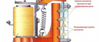
To turn off the starting capacitor, you can use an additional relay K1, then there is no need for toggle switch SA1, and the capacitor will turn off automatically (Fig. 5)
When you press the SB1 button, relay K1 is activated and the contact pair K1.1 turns on the magnetic starter KM1, and K1.2 turns on the starting capacitor Sp. The magnetic starter KM1 is self-locking using its contact pair KM 1.1, and contacts KM 1.2 and KM 1.3 connect the electric motor to the network. The “Start” button is kept pressed until the engine fully accelerates, and then released. Relay K1 is de-energized and turns off the starting capacitor, which is discharged through resistor R2. At the same time, the magnetic starter KM 1 remains switched on and provides power to the electric motor in operating mode. To stop the electric motor, press the “Stop” button. In an improved starting device according to the diagram in Fig. 5, you can use a relay of the MKU-48 type or the like.
The use of electrolytic capacitors in electric motor starting circuits.
When connecting three-phase asynchronous electric motors to a single-phase network, as a rule, ordinary paper capacitors are used. Practice has shown that instead of bulky paper capacitors, you can use oxide (electrolytic) capacitors, which are smaller in size and more affordable to purchase. An equivalent replacement diagram for conventional paper is shown in Fig. 6
Connecting an electric motor: a practical example
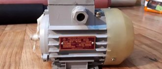
Let's say you have an asynchronous electric motor designed to be connected to a three-phase AC network. Power – 0.4 kW, motor type – AOL 22-4. Main characteristics for connection:
- Power – 0.4 kW.
- Supply voltage – 220 V.
- The current when operating from a three-phase network is 1.9 A.
- The motor windings are connected using a star circuit.
Now it remains to calculate the capacitors to start the electric motor. The motor power is relatively small, therefore, to use it in a household network, you only need to select a working capacitor; there is no need for a starting capacitor. Using the formula, calculate the capacitance of the capacitor: C (slave) = 66*P (motor) = 66*0.4 = 26.4 µF.
You can use more complex formulas; the capacity value will differ slightly from this. But if there is no capacitor suitable for the capacitance, you need to connect several elements. When connected in parallel, the containers are folded.
Star connection method
Here, to operate a three-phase electric motor, a 220-volt phase is passed through one of its windings, and a linear voltage of 380 volts is passed through the other two windings. The working capacitor is connected to the output winding conductors, two of which are output for direct connection to a single-phase electrical network, and the remaining wire is connected to the capacitor through the mains phase. Experts note that connecting using the triangle method is easier. In addition, power losses will be less than when powered by a star. Therefore, if possible, you should use a triangle, but if the model of your electric motor does not support this connection method, then the only option left is with a star.
note
Now you know which capacitors are best to use to start an electric motor. But the power will drop by about 20-30%. If a simple mechanism is set in motion, it will not be felt. The rotor speed will remain approximately the same as indicated in the passport. Please note that if the motor is designed to operate from a 220 and 380 V network, then it is connected to a household network only if the windings are connected in a triangle. Carefully study the tag; if it only has the designation of a “star” circuit, then in order to work in a single-phase network you will have to make changes to the design of the electric motor.
The function of stabilizers is that they act as capacitive energy fillers for stabilizer filter rectifiers. They can also transmit signals between amplifiers. To start and operate for a long period of time, capacitors are also used in the AC system for asynchronous motors. The operating time of such a system can be varied using the capacitance of the selected capacitor.
The first and only main parameter of the above-mentioned tool is capacity. It depends on the area of the active connection, which is isolated by a dielectric layer. This layer is practically invisible to the human eye; a small number of atomic layers form the width of the film.
That is, a capacitor is created in order to accumulate, store and transmit a certain amount of energy. So why are they needed if you can connect the power source directly to the engine. It's not that simple. If you connect the motor directly to a power source, then at best it will not work, at worst it will burn out.
In order for a three-phase motor to work in a single-phase circuit, you need a device that can shift the phase by 90° on the working (third) terminal. The capacitor also plays the role of a kind of inductor, due to the fact that alternating current passes through it - its surges are leveled out due to the fact that, before operation, in the capacitor, negative and positive charges are evenly accumulated on the plates, and then transferred to the receiving device.
There are 3 main types of capacitors:
The operating principle of a single-phase 220 V electric motor.
A magnetic field is generated in the stator of a 220 V single-phase electric motor. This is the impulse that drives the rotor. To imagine how an electric motor functions, it is worth simulating the following situation.
For example, there is no voltage in the starting winding. The formation of a magnetic field can be started by connecting the main winding to the network. Its work is based on pulsation, while the space remains at rest. The magnetic field is divided into two parts, each of which rotates in directions opposite to each other, at the same frequency. When the rotor is given an initial rotation, the engine will increase it over time. In this case, the frequency of the element and the magnetic field itself differs. The difference in indicators is defined as slip.
A driving force arises from magnetic fluxes. This is the law of electromagnetic induction. The driving force generates two types of current. One of them is reverse, the second is direct. The rotor speed is directly proportional to the slip rate. According to Ampere's law, a magnetic field, when interacting with a reverse current, creates rotation.
Description of types of capacitors and calculation of specific capacitance
- Connection diagram for starting capacitors
For electric motors with low frequencies, an electrolytic capacitor would be an ideal option; it has the maximum possible capacitance, which can reach a value of 100,000 μF. In this case, the voltage can fluctuate from standard 220 V to 600 V. Electric motors, in this case, can be used in tandem with an energy source filter. But at the same time, when connecting, it is necessary to strictly observe polarity. The oxide film, which is very thin, acts as electrodes. Electricians often call them oxide.
Read also: What is the name of the hexagon shape?
- It is better not to use polar ones in a system connected to an alternating current network , in this case the dielectric layer is destroyed and the device heats up and, as a result, a short circuit occurs.
- Non-polar ones are a good option , but their cost and dimensions are significantly higher than electrolytic ones.
When choosing the best option, you need to consider several factors. If the connection occurs through a single-phase network with a voltage of 220 V, then a phase-shifting mechanism must be used to start. Moreover, there should be two of them, not only for the capacitor itself, but also for the engine. The formulas used to calculate the specific capacitance of a capacitor depend on the type of connection to the system; there are only two of them: triangle and star.
I1 – rated motor phase current, A (Amps, most often indicated on the motor packaging);
Umains – mains voltage (the most standard options are 220 and 380 V). There are also higher voltages, but they require completely different types of connections and more powerful motors.
where Cn is the starting capacitance, Cp is the working capacitance, Co is the switched capacitance.
So as not to strain with calculations, smart people derived average, optimal values, knowing the optimal power of electric motors, which is denoted by M. An important rule is that the starting capacity should be greater than the working capacity.
With a power of 0.4 to 0.8 kW: working capacitance – 40 µF, starting power – 80 µF, From 0.8 to 1.1 kW: 80 µF and 160 µF, respectively. From 1.1 to 1.5 kW: Av – 100 µF, Sp – 200 µF. From 1.5-2.2 kW: Av – 150 µF, Sp 250 µF; At 2.2 kW, the operating power should be at least 230 μF, and the starting power should be 300 μF.
When a motor designed to operate at 380 V is connected to an alternating current network with a voltage of 220 V, half of the rated power is lost, although this does not affect the speed of rotation of the rotor. When calculating power, this is an important factor; these losses can be reduced with a “delta” connection diagram; the engine efficiency in this case will be 70%.
It is better not to use polar capacitors in a system connected to an alternating current network, in this case the dielectric layer is destroyed and the device heats up and, as a result, a short circuit occurs
Types of capacitor motors
The connection diagram, in which a capacitor asynchronous motor is started only from a starting capacitor, has one significant drawback. During operation, the magnetic field does not remain circular or elliptical, performance indicators drop, and the electric motor heats up. In this case, for optimal operation, a working capacitor is included in the circuit, providing a constant phase shift, and not only at the time of start-up.
Note that two groups of capacitor motors can be distinguished:
- The capacitor is needed only for starting, then it is called starting. These are usually low-power devices.
- The capacitor is needed for constant operation, in this case it is called a working one. In high-power machines (several kW), there may not be enough torque to start under load, and then an additional starting capacitor is connected. Most often this is done using the PVS button.
You can find out more about the connection diagram and how to distinguish these types of single-phase motors in the following video clip:
The international classification uses designations for types of capacitor asynchronous motors:
- motor with capacitor start/winding operation (inductance) (CSIR);
- capacitor start/capacitor run (CSCR) motor;
- permanent split capacitance (PSC) motor.
It’s easy to imagine how such a scheme works: a large-capacity starting capacitor ensures the engine starts, and after gaining power, a smaller-capacity worker provides the most suitable operating mode and rotor speed.
For special cases, when it is necessary to maintain the required rotor speed at different loads for working capacitors, different capacitors are selected with the ability to switch them.
To change the direction of rotation, in other words, turn on reverse, you need to swap the ends of one of the windings. To do this, it is convenient to use a 6-pin toggle switch.
Connection diagram "Triangle"
The connection itself is relatively easy; the current-carrying wire is connected to the starting capacitor and to the motor (or motor) terminals. That is, if we take it more simply, there is a motor; it contains three conductive terminals. 1 – zero, 2 – working, 3 – phase.
The power wire is stripped and there are two main wires in a blue and brown winding, the brown one is connected to terminal 1, one of the capacitor wires is also connected to it, the second capacitor wire is connected to the second working terminal, and the blue power wire is connected to the phase.
If the motor power is small, up to one and a half kW, in principle only one capacitor can be used. But when working with loads and high powers, it is mandatory to use two capacitors; they are connected in series, but between them there is a trigger mechanism, popularly called “thermal”, which turns off the capacitor when the required volume is reached.
You need to understand that the motor winding itself already has a star connection, but electricians use wires to turn it into a delta. The main thing here is to distribute the wires that go into the junction box.
Connection diagram “Triangle” and “Star”
Tips for use
Determining the required characteristics and choosing a model usually requires considerable effort. In this regard, it makes sense to take into account a few tips:
- It is mandatory to use a starting capacitor when working with high-power motors or in cases where it is necessary to start rotation of the shaft with a load.
- Motors smaller than 1 kW can usually be operated without the use of a starting capacitor. Such motors are often used in household appliances.
When connecting the starting circuit, you must carefully follow all the necessary rules. An error can lead to a breakdown or emergency.