At all times, both world-famous and so-called scientists were interested in the issue of obtaining free electricity.
As a result, a wide variety of schemes and methods for producing alternative electricity were created. But, unfortunately, there are very few truly effective methods.
In our article we will talk about ways to generate electricity from the ground, and find out if this is even possible.
To what extent is it possible to obtain electricity from the earth?
Before studying all the technological intricacies of generating electricity from the earth, you should ask the question: “Is this possible?”
There is an opinion that a lot of different energy has been accumulated in the bowels of the earth, and with the help of a special device this energy can be used constantly.
But this opinion is erroneous, since the extraction of electricity requires a clear plot of land and metal pins installed on it.
But over time, under the influence of certain factors, oxidation of the metal will begin to occur. As a result, electricity production will come to an end.
It is also necessary to take into account the type of soil, the quality of which has a direct impact on the amount of electricity extracted from it.
It should be borne in mind that, as a rule, the electricity extracted from the ground is only enough to operate a small light bulb or two or three LEDs.
To turn on more powerful devices, higher power will be required, and therefore a larger plot of land.
Summarizing the above, we can conclude that generating electricity from the ground is possible, but this can hardly be called an alternative power source.
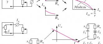
The idea of practical use of a magnetic field appeared long before the theories of modern physics. And the main thing in this idea was the desire to use the “eternal” magnetization of materials to obtain useful work or “free” electrical energy.
Attempts to practically use a constant magnetic field in engines or generators do not stop. The advent of modern rare-earth magnets with high coercivity has fueled interest in such developments. An abundance of ingenious designs of varying degrees of efficiency have filled the information space. Among them, the mover of the Japanese inventor Kohei Minato stands out.
Minato spent many years developing a magnetic motor of his own design, which he said was invented during a piano concert. He patented his engine in 46 countries.
Among many other similar designs, the Minato engine stands out for its very high efficiency. Without going into details of the design of the magnetic motor, which are still hidden in patent descriptions, it is necessary to note several of its features.
In its magnetic motor, sets of permanent magnets are located on the rotor at certain angles to the axis of rotation. The passage of the “dead” point by magnets, which, in Minato’s terminology, is called the “collapse” point, is ensured by applying a short powerful pulse to the electromagnetic stator coil.
It was this feature that provided the Minato design with high efficiency and quiet operation at high rotation speeds. But the assertion that the engine efficiency exceeds unity has no basis.
To analyze the Minato magnetic engine and similar designs, consider the concept of “hidden” energy. Latent energy is inherent in all types of fuel: for coal it is 33 J/gram; for oil – 44 J/gram. But the energy of nuclear fuel is estimated at 43 billion of these units. According to various, contradictory estimates, the latent energy of a permanent magnet field is about 30% of the potential of nuclear fuel, i.e. it is one of the most energy-intensive energy sources.
But using this energy is far from easy. If oil and gas, when ignited, immediately releases all its energy potential, then with a magnetic field everything is not so simple. The energy stored in a permanent magnet can perform useful work, but the design of the movers is very complex. An analogue of a magnet can be a battery of very high capacity with an equally large internal resistance.
Therefore, several problems immediately arise: it is difficult to obtain high power on the engine shaft with its small dimensions and weight. Over time, as the stored energy is consumed, the magnetic motor will lose its power. Even the assumption that energy is replenished by the Earth's magnetic field cannot eliminate this shortcoming.
The main disadvantage is the requirement for precision assembly of the engine design, which prevents its mass development. Minato is still working on determining the optimal placement of permanent magnets.
- | Fuel-free generator - an alternative source of electricity generation
- | An autonomous fuel-free electric generator will replace a wind generator and solar panels
- | John Searle's fuel-free generator - energy for the third millennium
If a traditional asynchronous motor is made of modern expensive materials, for example, windings made of silver, and the magnetic core is made of a thin amorphous steel tape (glass metal), then at a price comparable to a magnetic motor we will get close efficiency. At the same time, asynchronous motors will have a significantly longer service life with ease of manufacture.
Obtaining electricity from grounding and zero phase
If you live in a private house, then this method is ideal, but only if there is a ground loop.
Not many people know that there is a difference of approximately 10-20V between the zero phase and ground potentials.
Therefore, these phases can be represented as a free source of electricity from the ground. And using a transformer, these potentials can be increased.
When using this method, the electricity meter is not used, so electricity is free.
This kind of voltage can be determined using either a voltmeter or a low-voltage light bulb, which is connected between the neutral wire and the phase.
You should be very careful when using this method, because if they are mixed up, you can get an electric shock.
Since the pipeline is not very effective as a grounding conductor, it would be more advisable to use a special design consisting of metal pins buried a meter deep in the ground.
How to determine phase and zero with a multimeter
In addition to using an indicator screwdriver, you can also use a multimeter to find the phase and neutral wires.
Today, there are many models of multimeters on sale, but the method that we will now consider can be used on absolutely all models (regardless of functionality and cost). For example, I have a DT9208A digital multimeter.
The first step is to set up the device to measure alternating voltage. We insert the probes into the appropriate connectors (in my case these are “VΩCX+” and “com”). Next, we set the mode switch to the AC voltage measurement sector at a value of 750 Volts.
There are two ways to determine phase and zero with a multimeter.
The first method is contact
We insert one probe into the socket connector (it doesn’t matter which one is red or black), and clamp the second probe with two fingers. If the readings on the device are close to “0”, this means that you have touched the neutral conductor in the socket.
Now we move the probe to another socket of the socket. If the readings on the device differ significantly by 20-60 Volts (can reach up to 100 Volts), this means that you have touched a phase wire.
The numbers on the device may be different, it all depends on the person’s shoes, floor covering, room humidity, etc. Accordingly, the better the insulation of the floor and shoes, the lower the voltage value will be shown by the device.
The second method is contactless
The second method is non-contact, that is, without touching the multimeter probe with your fingers. We take one of the probes and insert it into the socket of the socket, we simply keep the second one near the device and do not touch anything with it. If a “zero” is connected to the socket pole, the device will show zero values.
We move the probe to another socket of the socket; we also do not touch anything with the second one. If a “phase” is connected to this pole of the socket, the device will show 3-10 Volts (up to 15 Volts).
As you can see in the photo, in my case, when determining phase and zero with a multimeter, the device shows 10 (11) Volts and 0, respectively.
Electroplating element
To obtain electricity from the ground on your own, this method is the most effective and simplest. To implement it, electrodes made of zinc and copper are used.
Various nails, plates, and pins can be used as electrodes. But, since, unlike copper, zinc is not so common, it can be easily replaced with galvanized iron.
The electrodes are buried a meter into the ground at a distance of 50 centimeters from each other. In this design, zinc electrodes will act as the anode, and copper electrodes will act as the cathode.
Using this method, you can obtain electricity with a voltage of approximately 1.1V.
The area of the electrodes of the above-mentioned design is an important point. The current strength that can be obtained with this method will depend on their area.
Sometimes a zinc electrode is watered with a saline or alkaline solution. This is necessary to keep the ground moist. It depends on this whether the structure will produce current or not.
The higher the current required, the greater the number of parallel-connected electrodes required. Almost all rechargeable batteries have a similar structure.
But it should be borne in mind that this system is not eternal, and will eventually fail due to the destruction of the electrodes.
Symbols and designations on diagrams
In the case of marking network wires, you can find two main signs of mass:
- PE – protective conductor marking (yellow-green color)
- PEN – designation of a neutral conductor that also acts as a protective conductor (blue)
In the case of grounding symbols on circuit diagrams, you will encounter two:
| General symbol for ground (grounding) |
| A symbol indicating a grounding clamp that has a protective function against electric shock. |
Many devices replace the grounding-type power plug with a plug that does not have a hole for the grounding pin. This does not mean that the device is not protected against electric shock. The body of the device usually has a so-called nameplate, on which you can find a symbol of two squares (one inside the other).
This means that the device does not have accessible external conductive elements (the housing is made of plastic), and therefore there is no need to ground it.
Attention! The presence of a plug without a hole on the grounding pin does not indicate that the device is adequately protected against electric shock. This is only indicated by the above symbol.
Electricity production in accordance with the Belousov method
The author of books about obtaining free energy, Valery Belousov, spent many years studying such a natural phenomenon as lightning and the impact it has on people.
As a result of these many years of work, methods were developed for generating electricity from the soil.
His method produces enough electricity to power a low-power light bulb. Valery Belousov's method is very easy to implement on your own, and it is ideal for country use.
Summarizing all of the above, we can conclude that it is quite possible to obtain energy from the earth, but it is so insignificant that it is difficult to call it an alternative source. For these purposes, it is better to use natural resources.
Methods for creating grounding
All electrical components are grounded in such a way that they are physically connected to the ground (soil). Let us immediately warn you that taking the grounding wire out of the house and plugging it directly into the ground is not a good and effective solution. The ground wire must be connected to something that will have a much larger contact area with the ground and will withstand changes in humidity and temperature over decades. This element is called the ground electrode.
Ground contact surface is important when it comes to ground resistance. The lower the resistance, the better (the sooner the electrical potential in case of problems will be zero).
Currently, there are several popular solutions for the manufacture of ground electrodes, let us mention a few of them:
- An iron rod thrust several meters into the ground, ending at the top with a connection for connecting a grounding conductor. The length of the rod depends on the type of soil. The lower the electrical resistance of the earth, the shorter the rod can be. In many cases, the use of this type of ground electrode may be insufficient due to the too small contact surface with the ground and the resulting high electrical resistance.
- Using steel tape. Wrap around the house about 80-100 cm underground. At one point it is connected to the main ground conductor, which is removed from the electrical system using a connector.
- Connecting the grounding conductor to a rod that extends from the reinforced concrete base of the building. That is, connecting the ground to a foundation that has a large contact area with the ground and, in addition, does not require additional installation costs. You just need to think about it at the stage of building a house.