DC voltage oscillogram
Let's first clarify what we mean by “constant voltage”.
As Wikipedia tells us, constant voltage (also known as direct current) is a current whose parameters, properties and direction do not change over time. Direct current flows in only one direction and its frequency is zero. We looked at the DC oscillogram in the article Oscilloscope. Operating Basics:
As you remember, on the graph we have time voltage vertically (Y-axis).
In order to convert a single-phase alternating voltage of one value into a single-phase alternating voltage of a smaller (possibly larger) value, we use a simple single-phase transformer. And in order to convert it into a constant pulsating voltage , we connected a Diode Bridge after the transformer. The output received a constant pulsating voltage. But with such tension, as they say, you can’t change the weather.
But how can we get out of the pulsating constant voltage
get the most real constant voltage?
To do this, we need just one radio component: a capacitor. And this is how it should be connected to the diode bridge:
This circuit uses an important property of a capacitor: charging and discharging. A capacitor with a small capacity charges quickly and discharges quickly. Therefore, in order to get an almost straight line on the oscillogram, we must insert a capacitor of decent capacity.
Dependence of ripple on capacitor capacitance
Let's take a practical look at why we need to install a large capacitor. In the photo below we have three capacitors of different capacities:
Let's look at the first one. We measure its value using our LC meter. Its capacity is 25.5 nanoFarads or 0.025 microFarads.
We connect it to the diode bridge according to the diagram above
And we cling to the oscilloscope:
As you can see, the pulsations still remain.
Well, let's take a capacitor with a larger capacity.
We get 0.226 microfarads.
We connect it to the diode bridge in the same way as the first capacitor and take readings from it.
And here is the actual oscillogram
Not... almost, but still not the same. The pulsations are still visible.
Let's take our third capacitor. Its capacity is 330 microfarads. Even my LC meter cannot measure it, since my limit on it is 200 microfarads.
We hook it to the diode bridge and take an oscillogram from it.
And here she actually is
Here you go. It's a completely different matter!
So, let's draw some conclusions:
– the larger the capacitance of the capacitor at the output of the circuit, the better. But don’t overuse the capacity! Since in this case our device will be very large, because capacitors of large capacities are usually very large. And the initial charge current will be huge, which can lead to an overload of the supply circuit.
– the lower the resistance load at the output of such a power supply, the greater the ripple amplitude will appear. They combat this with the help of passive filters, and also use integrated voltage stabilizers, which produce the purest DC voltage.
How to choose radio elements for a rectifier
Let's return to our question at the beginning of the article. How can you still get a direct current of 12 Volts at the output for your needs? First you need to select a transformer so that at the output it produces... 12 Volts? But you didn’t guess right! We will receive effective voltage from the secondary winding of the transformer.
Umax – maximum voltage, V
Therefore, to obtain 12 Volts of direct voltage, the output of the transformer must be 12/1.41 = 8.5 Volts of alternating voltage. Now that's order. In order to obtain such a voltage on the transformer, we must reduce or add transformer windings. The formula is here. Then we select diodes. We select diodes based on the maximum current in the circuit. We are looking for suitable diodes using datasheets (technical descriptions for radio elements). We insert a capacitor with a decent capacity. We select it based on the fact that the constant voltage on it does not exceed that written on its marking. The simplest constant voltage source is ready for use!
By the way, I got a 17 Volt constant voltage source, since the transformer has 12 Volts at the output (multiply 12 by 1.41).
And finally, to make it easier to remember:
We must read the continuation of this article.
Very often, users of lighting electrical devices and SBT are interested in: “How can I get 12V or other low voltage from 220 volts without a transformer?” This question is usually asked by owners of electronic equipment and equipment powered by power supplies on a step-down network transformer. This is all the more important since the weight and dimensions of the power supply unit (PSU) often exceed those of the powered gadget or stationary device.
Basic ways to downgrade
For example, a “running” transformer with a frequency of 50 Hz with a relatively low power of 200 W, made on transformer hardware, weighs more than 1 kilogram and costs from $9–18. This not only makes the power supply bulky, but also significantly increases the cost of the device.
The transformers implement a classic scheme for reducing and then converting alternating voltage (AC) to direct voltage (DC) along the “transformer → rectifier → stabilizer” circuit.
There is a more complex scheme for constructing a “rectifier → pulse generator → transformer → rectifier → stabilizer” switching power supply, which has smaller dimensions.
The advantage of the above schemes is galvanic isolation. When the load circuit is closed to “zero,” it prevents equipment failure and reduces the risk of electric shock to a person.
However, the smallest 12 V power supplies are transformerless power supplies, which produce:
- Use a ballast capacitor to reduce the voltage.
- Using a ballast resistor, excess voltage is suppressed.
- An unregulated autotransformer removes the required voltage and smoothes it with a choke.
Ballast capacitor
Today, installing a quenching capacitor has become a very popular means of reducing voltage among radio amateurs. This universal method is widely used to power LED lamps and in chargers of low-power batteries. Installing a radio element in the gap in the power supply network of the diode bridge allows you to obtain the required current in the electrical circuit without dissipating significant power into heat.
The circuit of a simple capacitor (transformerless) power supply with a minimum number of radio elements and a voltage of 12 V and a power of 0.18 W is as follows:
Any device designed for a constant voltage of 12 V with an operating amperage ≤ 0.15A is used as P1. Capacitor C1 is a ballast capacitor, shunted by resistor R1. It is designed to prevent electric shock from the charge accumulated on the plates of capacitor C1. With its high resistance of hundreds of kOhms, resistor R1 does not affect the flow of current through the capacitance during the working session.
However, after the power supply is turned off, a discharge current from the capacitor plates passes through the resistor for a period of time measured in several seconds. Electrolytic capacitor C2, connected in parallel to the load after the diode bridge, smoothes out the ripples of the rectified current.
The symbiosis of a rectifier and a parametric stabilizer with a regulating element will significantly reduce the dependence of the output voltage on the load resistance of the power supply unit. This modification is carried out by soldering a 12 volt zener diode in parallel to P1.
Using a resistor
The method is suitable for powering a low-current load, for example, an LED or a low-power LED lamp. The main disadvantage of a resistive circuit is low efficiency due to the dissipation of a large amount of active power spent on heating the resistor. In the simplest version, the power supply is a voltage divider with resistors installed after the diode rectifier, from the lower arm of which the voltage is removed.
Stabilization is carried out by changing the resistance of one of the divider arms: resistor values are selected in such a way as to reduce the output voltage to acceptable values.
Autotransformer or inductor with similar winding logic
The autotransformer does not have a secondary winding: the output voltage is removed from one single winding on a toroidal magnetic circuit, which is simultaneously used to supply a mains voltage of 220 V, 50 Hz.
The principle of operation is similar to LATR, only the voltage removed from the turns has a certain fixed value. Therefore, replacing a power transformer with an autotransformer increases the efficiency of the power supply and significantly reduces the size and weight of the device (other things being equal, the weight and dimensions of the transformer are 1.5 times larger than the replacement product).
Circuit diagram of an autotransformer with a fixed voltage U2.
However, an unregulated autotransformer has a significant drawback: it does not protect against voltage surges and impulses induced in the network. Low-frequency (LF) and high-frequency (HF) ripples, network noise and parasitic harmonics will be significantly reduced if a choke is installed in the output circuit. In tandem with an autotransformer, a choke with high inductance ≤ 0.5–1.0 GN is used, installed in series with the load.
The inductive element accumulates the energy of the supply network in the magnetic field of the coil and then transfers it to the load. An inductor in an electrical circuit counteracts changes in current in the electrical circuit. During a sharp drop, the coil maintains the flow of current, and during a sharp increase, it limits it, preventing it from increasing quickly. Compact AC chokes are used in boosters for energy-saving lamps and LED drivers that power LED lamps.
Alternating current and its parameters
With alternating current, the direction and magnitude change cyclically over time. The cycle of one complete change (oscillation) is called period (T) , and its inverse value is called frequency (f) . The letter designation of alternating current is AC , an abbreviation for Alternating Current (alternating current), and graphically it is indicated by a sine wave segment:
̴
After this sign the voltage is indicated, sometimes the frequency and number of phases.
Alternating current is characterized by the following parameters:
| Characteristic | Designation | Unit | Description |
| Number of phases | Single phase | ||
| Three-phase | |||
| Voltage | U | volt | Instantaneous value |
| Amplitude value | |||
| Effective value | |||
| Phase | |||
| Linear | |||
| Period | T | second | Time of one complete oscillation |
| Frequency | f | hertz | Number of oscillations per second |
Single-phase current in its pure form is obtained using gasoline and diesel generators. In other cases, it is part of a three-phase voltage, which consists of three voltages varying according to a sinusoidal law, evenly shifted relative to each other. This time shift is called the phase angle and is 1/3T.
Four wires are used to transmit three-phase voltages. One is their common point and is called zero (N), and the other three are called phases (L1, L2, L3) .
Three-phase AC voltage graphs
The voltage between phases is called linear , and between phase and zero - phase , it is √3 times less than linear. In our network, the phase voltage is 220 V, and the linear voltage is 380 V.
The instantaneous value of alternating current voltage is understood as its value at a certain point in time t. It changes with frequency f. The instantaneous voltage value at the maximum point is called the amplitude value. But this is not what voltmeters and multimeters measure. They show a value √2 times smaller, called the effective or effective voltage value . Physically, this means that a direct current voltage of this magnitude will do the same work as the measured alternating voltage.
Characteristics of three-phase current
Transformerless power supply: possible schematic solutions
Linear stabilizer chip
You can assemble a simple driver (stabilized current source) with your own hands using an inexpensive ($0.3) linear stabilizer chip LM317AMDT. The input of the DC-AC converter is supplied with a mains voltage of 220 V, 50 Hz.
A stabilized voltage of 12 V is obtained on the IC with a minimum set of elements in the harness (in the simplest version, only R1 and R2 are used). By selecting the value of the resistors, you can regulate the current in the load; with a total LED current of up to 0.3 A, the microcircuit works perfectly without a radiator. Below is a typical circuit diagram of a device based on the LM317 chip:
Charger
The most budget option, of course, is to use a charger from a cell phone. The charger board has very small dimensions and is suitable for powering a 12 V gadget with a power ≤ P rated. power supply. It is only necessary to replace the half-wave rectifier with a rectifier with double the voltage (add one diode and capacitor each). After modernization, we get the required 12 volts with a current of 0.5A and full isolation from the network.
As an alternative that does not require intervention in the design, a step-up DC-DC voltage converter (for example, 2-amp, 30mm x 17mm x 14mm, costing $1) with a USB connector can be connected to the output of the charger through an adapter. All you need to do is set the trimming resistor to the required voltage of 12 V and connect the converter to a gadget or stationary power receiving device.
Converting AC to DC and vice versa
The process of obtaining direct current from alternating current is called rectification , and the devices are called rectifiers . The main part of the rectifier is a semiconductor diode , which conducts current in only one direction. As a result of rectification, a pulsating current is obtained, changing its value over time, but not changing its sign.
Then the ripples are eliminated using filters , the simplest of which is a capacitor . It is impossible to completely eliminate ripple, and its final level depends on the rectifier circuit and the quality of the filter. The complexity and cost of rectifiers depends on the magnitude of the output ripple and the maximum output power.
Diagram of a simple rectifier Rectifier operation graphs
Inverters are used to convert to alternating current . The principle of their operation is to generate an alternating voltage with a shape as close as possible to a sinusoidal one. An example of such a device is a car inverter for connecting household appliances or tools to the on-board network.
The better and more expensive the inverter, the greater its power or more accurately the voltage it produces approaches a sine wave.
Rate the quality of the article:
What can 12 or 24 volt voltage be used for in everyday life?
In domestic environments, low voltage power supplies are often used. Portable/stationary electrical and electronic devices, as well as some lighting devices, are powered from 12 or 24V DC voltage:
- cordless electric drills, screwdrivers and electric saws;
- stationary pumps for watering gardens;
- audio-video equipment and radio-electronic equipment;
- video surveillance and alarm systems;
- battery-powered radios and players;
- laptops (netbooks) and tablets;
- halogen and LED lamps, LED strips;
- portable ultraviolet irradiators and portable medical equipment;
- soldering stations and electric soldering irons;
- chargers for mobile phones and power banks;
- low-current power supply networks in places with high humidity and landscape lighting systems;
- children's toys, Christmas tree garlands, aquarium pumps;
- various homemade radio-electronic devices, including those based on the popular Arduino platform.
Most devices run on batteries and Li-ion batteries, but the use of commodity items is not always justified in terms of operating costs. Batteries can be charged 300–1500 times, but galvanic cells with high energy capacity and low self-discharge current are expensive. It will be noticeably cheaper to purchase batteries, especially salt and alkaline ones, but such elements will have to be changed frequently. Moreover, to provide a supply voltage of 12 V, you will need 8 series-connected AA or AAA batteries or 1.5-volt “tablets” in a 27A housing.
Therefore, in places with access to a 220 V 50 Hz household network, it is more rational to use a power supply to power electrical receivers with an amperage of more than 0.1 A.
Very often, users of lighting electrical devices and SBT are interested in: “How can I get 12V or other low voltage from 220 volts without a transformer?” This question is usually asked by owners of electronic equipment and equipment powered by power supplies on a step-down network transformer. This is all the more important since the weight and dimensions of the power supply unit (PSU) often exceed those of the powered gadget or stationary device.
Methods for generating electricity
Today it is impossible to imagine your life without electricity. Every day, the entire population of our planet uses millions of watts of electricity to ensure normal life. But once again, when turning on the electric kettle, a person does not think about what path the electricity had to travel so that he could brew himself a morning cup of aromatic coffee.
There are several ways to generate electricity:
- from thermal energy;
- from the energy of water;
- from atomic (nuclear) energy;
- from wind energy;
- from solar energy, etc.
In order to understand the nature of the occurrence of electrical energy, let's consider several examples.
Basic ways to downgrade
For example, a “running” transformer with a frequency of 50 Hz with a relatively low power of 200 W, made on transformer hardware, weighs more than 1 kilogram and costs from $9–18. This not only makes the power supply bulky, but also significantly increases the cost of the device.
The transformers implement a classic scheme for reducing and then converting alternating voltage (AC) to direct voltage (DC) along the “transformer → rectifier → stabilizer” circuit.
There is a more complex scheme for constructing a “rectifier → pulse generator → transformer → rectifier → stabilizer” switching power supply, which has smaller dimensions.
The advantage of the above schemes is galvanic isolation. When the load circuit is closed to “zero,” it prevents equipment failure and reduces the risk of electric shock to a person.
However, the smallest 12 V power supplies are transformerless power supplies, which produce:
- Use a ballast capacitor to reduce the voltage.
- Using a ballast resistor, excess voltage is suppressed.
- An unregulated autotransformer removes the required voltage and smoothes it with a choke.
Ballast capacitor
Today, installing a quenching capacitor has become a very popular means of reducing voltage among radio amateurs. This universal method is widely used to power LED lamps and in chargers of low-power batteries. Installing a radio element in the gap in the power supply network of the diode bridge allows you to obtain the required current in the electrical circuit without dissipating significant power into heat.
The circuit of a simple capacitor (transformerless) power supply with a minimum number of radio elements and a voltage of 12 V and a power of 0.18 W is as follows:
Any device designed for a constant voltage of 12 V with an operating amperage ≤ 0.15A is used as P1. Capacitor C1 is a ballast capacitor, shunted by resistor R1. It is designed to prevent electric shock from the charge accumulated on the plates of capacitor C1. With its high resistance of hundreds of kOhms, resistor R1 does not affect the flow of current through the capacitance during the working session.
However, after the power supply is turned off, a discharge current from the capacitor plates passes through the resistor for a period of time measured in several seconds. Electrolytic capacitor C2, connected in parallel to the load after the diode bridge, smoothes out the ripples of the rectified current.
The symbiosis of a rectifier and a parametric stabilizer with a regulating element will significantly reduce the dependence of the output voltage on the load resistance of the power supply unit. This modification is carried out by soldering a 12 volt zener diode in parallel to P1.
Using a resistor
The method is suitable for powering a low-current load, for example, an LED or a low-power LED lamp. The main disadvantage of a resistive circuit is low efficiency due to the dissipation of a large amount of active power spent on heating the resistor. In the simplest version, the power supply is a voltage divider with resistors installed after the diode rectifier, from the lower arm of which the voltage is removed.
Stabilization is carried out by changing the resistance of one of the divider arms: resistor values are selected in such a way as to reduce the output voltage to acceptable values.
Autotransformer or inductor with similar winding logic
The autotransformer does not have a secondary winding: the output voltage is removed from one single winding on a toroidal magnetic circuit, which is simultaneously used to supply a mains voltage of 220 V, 50 Hz.
The principle of operation is similar to LATR, only the voltage removed from the turns has a certain fixed value. Therefore, replacing a power transformer with an autotransformer increases the efficiency of the power supply and significantly reduces the size and weight of the device (other things being equal, the weight and dimensions of the transformer are 1.5 times larger than the replacement product).
Circuit diagram of an autotransformer with a fixed voltage U2.
However, an unregulated autotransformer has a significant drawback: it does not protect against voltage surges and impulses induced in the network. Low-frequency (LF) and high-frequency (HF) ripples, network noise and parasitic harmonics will be significantly reduced if a choke is installed in the output circuit. In tandem with an autotransformer, a choke with high inductance ≤ 0.5–1.0 GN is used, installed in series with the load.
The inductive element accumulates the energy of the supply network in the magnetic field of the coil and then transfers it to the load. An inductor in an electrical circuit counteracts changes in current in the electrical circuit. During a sharp drop, the coil maintains the flow of current, and during a sharp increase, it limits it, preventing it from increasing quickly. Compact AC chokes are used in boosters for energy-saving lamps and LED drivers that power LED lamps.
Advantages and disadvantages of alternating voltage
So why did they choose alternating current rather than direct current for power supply?
When transmitting electricity, current passes through wires hundreds of kilometers long, heating them and dissipating energy into the air. This is inevitable for both direct and alternating currents. But the power loss depends only on the resistance of the wires and the current in them:
The power transmitted along the line is equal to:
It follows that as the voltage increases, less current is needed to transmit the same power, and the power loss decreases. This is why the voltage is increased on long power lines. There are lines for 6kV, 10kV, 35kV, 110kV, 220kV, 330kV, 500kV, 750kV and even 1150kV.
But in the process of transferring electricity from source to consumer, the voltage must be changed repeatedly. It is easier to do this on alternating current using transformers.
The disadvantages of alternating current appear when transmitting energy through cable lines. Cables have capacitance between phases and with respect to ground, and the capacitance conducts alternating current. A leak appears, heating the insulation and causing it to fail over time.
Transformerless power supply: possible schematic solutions
Linear stabilizer chip
You can assemble a simple driver (stabilized current source) with your own hands using an inexpensive ($0.3) linear stabilizer chip LM317AMDT. The input of the DC-AC converter is supplied with a mains voltage of 220 V, 50 Hz.
A stabilized voltage of 12 V is obtained on the IC with a minimum set of elements in the harness (in the simplest version, only R1 and R2 are used). By selecting the value of the resistors, you can regulate the current in the load; with a total LED current of up to 0.3 A, the microcircuit works perfectly without a radiator. Below is a typical circuit diagram of a device based on the LM317 chip:
Charger
The most budget option, of course, is to use a charger from a cell phone. The charger board has very small dimensions and is suitable for powering a 12 V gadget with a power ≤ P rated. power supply. It is only necessary to replace the half-wave rectifier with a rectifier with double the voltage (add one diode and capacitor each). After modernization, we get the required 12 volts with a current of 0.5A and full isolation from the network.
As an alternative that does not require intervention in the design, a step-up DC-DC voltage converter (for example, 2-amp, 30mm x 17mm x 14mm, costing $1) with a USB connector can be connected to the output of the charger through an adapter. All you need to do is set the trimming resistor to the required voltage of 12 V and connect the converter to a gadget or stationary power receiving device.
How to make a simple voltmeter with your own hands - diagrams and recommendations
Situations when a voltmeter should be at hand occur quite often.
To do this, there is no need to use a complex factory device. Making a simple voltmeter with your own hands is not a problem, because it consists of two elements: a pointer measuring unit and a resistor. True, it should be noted that the suitability of a voltmeter is determined by its input resistance, which consists of the resistances of its elements. But it is necessary to take into account the fact that there are different resistors with different values, and this means that the input resistance will depend on the installed resistor. That is, by choosing the right resistor, you can make a voltmeter to measure certain network voltage levels. The measuring device itself is more often evaluated by the indicator - relative input resistance per one volt of voltage, its unit of measurement is kOhm / V.
That is, it turns out that the input resistance in different measured areas is different, but the relative value is a constant indicator. In addition, the less the arrow of the measuring block deviates, the greater the relative value, and, therefore, the more accurate the measurements will be.
What can 12 or 24 volt voltage be used for in everyday life?
In domestic environments, low voltage power supplies are often used. Portable/stationary electrical and electronic devices, as well as some lighting devices, are powered from 12 or 24V DC voltage:
- cordless electric drills, screwdrivers and electric saws;
- stationary pumps for watering gardens;
- audio-video equipment and radio-electronic equipment;
- video surveillance and alarm systems;
- battery-powered radios and players;
- laptops (netbooks) and tablets;
- halogen and LED lamps, LED strips;
- portable ultraviolet irradiators and portable medical equipment;
- soldering stations and electric soldering irons;
- chargers for mobile phones and power banks;
- low-current power supply networks in places with high humidity and landscape lighting systems;
- children's toys, Christmas tree garlands, aquarium pumps;
- various homemade radio-electronic devices, including those based on the popular Arduino platform.
Most devices run on batteries and Li-ion batteries, but the use of commodity items is not always justified in terms of operating costs. Batteries can be charged 300–1500 times, but galvanic cells with high energy capacity and low self-discharge current are expensive. It will be noticeably cheaper to purchase batteries, especially salt and alkaline ones, but such elements will have to be changed frequently. Moreover, to provide a supply voltage of 12 V, you will need 8 series-connected AA or AAA batteries or 1.5-volt “tablets” in a 27A housing.
Therefore, in places with access to a 220 V 50 Hz household network, it is more rational to use a power supply to power electrical receivers with an amperage of more than 0.1 A.
Welding machine from “permanent” to “permanent”.
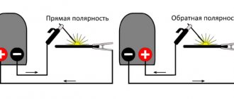
Most welding machines, especially homemade ones, are very far from perfect. We offer a diagram for fine-tuning a homemade welding machine from “change” to “permanent” with your own hands and you can use electrodes of any type (see Fig. 1).
Rice. 1 Diagram of a welding machine with a highly efficient inductive-capacitive filter that smoothes out rectified voltage ripples.
Let's go through the diagram.
Throttle L.
The core for it is taken from the choke of city lighting lamps 1N400N37-110. When removing old windings, it is necessary to preserve the cardboard spacers that provided the gap between the main and closing parts of the core (Fig. 2).
Rice. 2 Choke design from the choke core of street lighting lamps.
When reassembling, they are installed in place. The new winding is wound on only one side core - three layers of copper busbar with a cross-section of 4x6 mm, located evenly along the entire length of the core. The beginning of the inductor winding is connected to the block of capacitors C1 ... C6, and the end of the winding is connected to the “+” terminal (Fig. 1).
Rectifier and block of filter capacitors.
Diodes U01...U04 type D161-320 or similar, designed for average rectified current - above 250 A and reverse voltage - at least 200 V, are mounted on standard cast radiator-coolers, which must be insulated from each other and from the body of the welding machine with textolite plates. Capacitors 31...56 are electrolytic, type K50-3 or K50-7, two-section 250/290 (150+150 µF). The total capacity of the capacitor block is 1800 microfarads. It is most convenient to install them in one row on a textolite plate 4…6 mm thick.
Welding current regulator P (“ballast rheostat”}.
Made from one section of the limiting resistance of the DEK-256 overhead crane (Fig. 3).
This resistance is a ceramic pipe with a shaped spiral groove on the outer surface, into which a busbar made of a material with high resistivity, with a cross-section of about 20 mm2, is laid.
Step-down voltage converter with current up to 10 (12) amperes
Not long ago I published a review of a step-down converter module with a current of up to 20 amperes, but as was said then, this was already the second one I ordered from Aliexpress. Well, today is a review of what I received about a year ago instead of it with my first order. I didn’t order this particular converter, the seller mixed something up and sent me it instead of the 20 ampere option, I noticed it too late so I had to come to terms with it. But I decided to test it anyway and at the same time I found a link to this particular model from the seller who sent it.
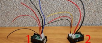
The packaging is still the same classic, antistatic bag, inside there is a compact converter, a board with two radiators on the sides.
Characteristics from the product page (original translation)
Input voltage: 4.5-30V Input voltage should not exceed 30V! Output voltage: 1.25-30V continuous adjustable Output current: 0-12A 100W to enhance heat up to 200W, Operating temperature: -40~+85 degrees Operating frequency: 300KHz Conversion efficiency: 95% maximum (efficiency related with input, output voltage, current, pressure difference) Short circuit protection: yes (current limit 14A), please try not to short circuit Overheat protection: yes (automatic shutdown of ultra temperature output) Input reverse connection protection: no, (for example, if you need, please, a series of diodes at the input) Installation: 4 pcs. 3 mm screws Connection: Connection terminal, without welding, V-IN input, V-OUT output, with housing modules for welding line output Module size: Length 60 mm Width 51 mm Height 22 mm
At a quick glance it looks neat, although as it turned out later, this is far from reality. On the input side there is a terminal block, a 15A fuse and a trimming resistor for setting the output voltage. Current regulation is not provided here. On the output side there is the same terminal block as at the input, an LED indicating the output voltage and a place for connecting a fan. I note that the terminal blocks are somewhat weak for the stated 10 amperes, and their overall quality leaves much to be desired, although they will work.
There are two capacitors installed at the input, three at the output, all have a capacity of 330 μF and a voltage of 35 volts, although they have some name written on them, but I simply call them nameless.
The layout is dense, the inductor is not fixed and is held in place only by the winding wire, the capacitors are placed tightly (apparently so that they do not freeze). When I examined it more closely, I noticed that the screw that presses the diode assembly was rusty...
The converter is built on the basis of the XL4016E1 PWM controller; the MBR2045CT diode assembly is installed on the second radiator. Both power components are isolated from the radiators; by the way, the radiators themselves are screwed to the board.
And this is where the fun begins. The fact is that, as it turned out, this chip has at least two versions of the datasheet, one old version 1.2 and a new one, version 1.3, while the old one claims a maximum current of 8 amperes and the presence of protection against overvoltage at the input, while the new one has this protection is not declared, but the load current is indicated as 12 amperes, i.e. one and a half times more.
I found screenshots of the first datasheet in the materials for my review of the converter with a stated current of 10A, and downloaded the second one from the chip manufacturer’s website. I think that many people remember the review of this converter model, although more than 4 years have passed since its publication.
At the same time, the block diagrams of both chips are identical, but the typical circuit is different, if the old version had an example with an output voltage of 5 volts and a current of 8A with an input voltage range of 8-40 volts, then the new one is more complicated, here it is stated: 1. V in the power range of 8-20 volts and an output of 5 volts, up to 9A is allowed 2. In the range of 20-36 volts and the same output voltage, you can load up to 12A 3. In this case, the typical mode is stated as 5 volts 12 amperes with an input of 8-36 volts, which does not agree with the first point.
By the way, the right diagram also shows the MBR2045 diode assembly, so the module manufacturer apparently simply did everything as specified by the manufacturer.
The soldering is average, but the traces of flux on the board look sad.
But there were some oddities here too. 1. For some reason, the fan connection contacts are labeled at the bottom as V_in and V_out. 2. There is an unsoldered connector and missing elements for PWM control of the converter. Judging by the inclusion, they go to the second pin of the chip (FB)
For comparison, photos of two converters, on the left 20A, on the right the one under review. At the same time, the 20A version costs only one and a half times more and, in addition to greater power, has a current limiting function.
To test the converter, I used a power supply based on RD6012 with an output current of up to 12A as a source.
According to the description, the maximum input voltage is stated as 30 volts, but at the same time, the converter worked without problems with an input voltage of 36 volts and a power of 150 W.
1, 2. With an input of 30 volts and no load, the output voltage is regulated in the full range and there is still a small margin in the direction of the trimming resistor 3, 4. Initially, 22 volts was set at the output, while the current consumption without load was 4 and 5 mA at the input 12 and 30 volts, respectively 5, 6. Since the indication LED is connected to the output, I set the minimum voltage at the output and measured the current again, now it was 3 and 2.8 mA.
Load tests and efficiency measurements were carried out in conjunction with an EBC-A10H electronic load, respectively, the maximum load current was 10A, and the maximum power was 150W. To reduce the influence of contacts and wires, the measuring wires were connected directly to the converter board, bypassing the terminal block.
Load test with an input voltage of 12 volts and an output voltage of 5 volts, a slight increase in the output voltage is noticeable at currents of more than 7A, before this value the voltage was stable. Although, of course, calling a voltage increase of 30 mV an increase is probably too strong.
With the same output, but input 30 volts, the situation is somewhat worse, the voltage has already increased by 0.18 volts, not that bad, but there is clearly a difference.
Input 24 volts and output 12 volts, everything was quite good here, there was also a rise, but only by 0.12 volts or 1%. I also checked with an input of 30 volts, an output of 15 volts and a current of 10A, I did not find any difference with the above.
But with a ratio of 30 volts input and 24 volts output at a current of 5A or more, the output voltage began to decrease. As a result, with a current of 6.35A and a power of 150W, the difference was 0.4 volts.
The efficiency was measured in three modes, 12-5 volts, 30-5 volts and 24-12 volts, the highest efficiency was obtained with an input of 24 and output of 12 volts, the lowest with an input of 30 volts and an output of 5 volts. On the horizontal axis, one is equal to a load current of 1 ampere.
Already during the preliminary tests, I noticed noticeable heating of the converter, but nevertheless I carried out a test with thermal heating. In the first mode, the input was 12 volts, the output was 5, the test took place in three stages: 20 minutes at a current of 5A, 20 minutes at a current of 7.5A and 5 minutes at 10A. In the latter case, I stopped the test because the temperature exceeded 110 degrees, the hottest was the inductor, but I would not say that the PWM controller was far behind it, I think the proximity of the inductor and its radiator also had an effect.
With an input of 24 volts and an output of 12 volts, the test was carried out in two modes, 20 minutes at a current of 5A and 20 minutes at 7.5A; the current did not rise higher, since even in this mode the temperature was about 106-107 degrees.
And finally, measuring the ripple amplitude at the output. The measurement was carried out with a bunch of 1 and 0.1 µF capacitors connected in parallel to the probe.
But here everything turned out to be very good, the oscillograms were taken in the mode: input 12 volts, output 5 volts, load 0, 2.5, 5 and 10A. Even in the most loaded mode, the ripple range was 25 mV, and at a current of 5A it was no more than 15 mV.
Also checked in other modes. On the left, the input is 30 volts, the output is 5, currents are 2.5, 5 and 10A, on the right the same currents, but the input is 24 volts and the output is 12. But even with an output of 12 volts and a load current of 10A, the ripples were about 30mV, which is also true for a board without output filters not bad, I think that adding an LC filter will easily reduce them several times more.
Conclusions. Yes, somehow it turned out that I not only didn’t think about writing this review, but also about buying this board at all. As you can see, this was not in vain, since the converter, in general, does not stand out in any way and, in my opinion, is inferior to the 20A version. I didn’t like the poor build quality, some dirt on the board, a rusty screw, weak terminal blocks. But at the same time, the board easily produces a current of up to 10 amperes and has a relatively low ripple level, so it may well be in demand for some applications.
In short, you can use it, but it’s better to pay a couple of dollars more and buy a 20A board.