It is difficult to imagine the modern world without electricity, the phone will remain without recharging, and watching a movie will simply become impossible. Yes, without this phenomenon life will seem difficult. But in order to receive it, you need a flow of energy, the physical component of which can be of a different nature. In electrical engineering, it is customary to divide batteries into two groups: by direct current or voltage . They can be ideal, but existing only in theory, and real, which can be seen in practice.
Ideal current source (generator)
First, let's consider an abstract option: the current created in this device is always the same . Based on Ohm's law, we can easily conclude that the voltage depends only on the resistance of the connected load . The internal resistance of such a battery has an infinite value, so it does not affect the main parameter. Due to the fact that the current value is constant, the power value of the theoretical unit is affected only by the resistance of the connected load. In the device, when a short circuit occurs, the main property of the source is also preserved.
Such an ideal element can only be created in theory; it is used in modeling electromagnetic processes. In practice, such a system is impossible to achieve, so let's consider a material variation.
Voltage formula
There is a formula in physics, although it has no practical application. The official formula is written like this.
voltage formula
Where
A is the work done by the electric field to move a charge along a section of the circuit, Joules
q - charge, Coulomb
U—voltage on a section of the electrical circuit, Volts
In practice, the voltage across a section of a circuit is derived through Ohm's law.
voltage from Ohm's law
Where
I - current, Amperes
R - resistance, Ohms
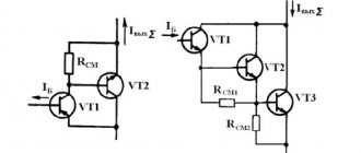
Real generator
The main difference between a real and an ideal device is the presence of internal resistance . The higher this parameter, the closer the element is to the improved version. It follows from this that the voltage and power values are finite, that is, they have a certain operating range. At the same time, the system also has a limitation on the connected load. When solving problems, a real device is depicted as an ideal one, with an internal resistance connected in parallel.
Operation of this unit is possible at idle (without external load) due to the fact that we have a closed circuit due to internal resistance. The output current during this mode is reduced to zero. When connected short (short circuit mode), we get the maximum value, and the output voltage drops to 0.
As an example of such a device, let's look at the inductor . This provision is valid at the moment the circuit opens. So the potential difference in this mode increases sharply compared to the previous state. It's all about the EMF of self-induction that occurs in this element. When the voltage increases, the coil accumulates energy, and when it decreases, it releases it into the network.
Another example is the secondary winding of a current transformer , which should always be short-circuited under normal operating conditions. Otherwise, if a break occurs in it, it will become a generator. It's all about the law of conservation of energy, so the power on the primary and secondary windings should be the same. The parameters of the primary winding are unchanged due to the design features of the transformer (the winding has one turn). If there is a break in the secondary winding, there will be no ordered movement of charged particles, and accordingly the voltage will increase sharply.
Ideal voltage source (EMF)
In an ideal device, the voltage is a constant parameter and does not depend on the value of the load current; at the same time, its internal resistance is 0. If the creation of this device were possible, then it would represent a source of infinite power. The amount of current and power with a connected load tended to an infinite number. But, as we know, power has a finite meaning.
The described power element is a theoretical concept; in practice, such conditions cannot be achieved, therefore it is used only in process modeling.
Question #9: “What is a current source and how is it different from a voltage source?”
A current source is an element, a two-terminal network, the current strength through which does not depend on the voltage at its terminals (poles). An EMF source is a two-terminal network, the voltage at the terminals of which does not depend on the current flowing through the source and is equal to its EMF.
They differ in internal resistance and conductivity. The current source has the maximum internal resistance and the minimum internal conductivity, and the EMF source has exactly the opposite.
Question No. 10: “Two-link formula for calculating error”
, where D0 is additive, and C
– multiplicative components of the absolute error (in this case indicated in relative units).
Question No. 11: “Draw a graph of the additive and multiplicative components of the absolute error”
Question No. 12: “Voltmeter characteristics”
Voltmeter Specifications
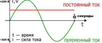
Normal operation of the voltmeter is possible at an air temperature not exceeding 25 - 30 ° C with a relative humidity of up to 80% at an atmospheric pressure of 630 - 800 mm Hg. Art. Mains frequency 50 Hz and voltage 220V (frequency up to 400 Hz). The measurement is greatly influenced by the shape of the AC supply voltage curve - a sinusoid with a harmonic coefficient of no more than 5%.
In this laboratory work, the parameters of the voltmeter can be obtained from the body of the voltmeter itself, namely the accuracy class, the instrument division value, internal resistance, etc.
LABORATORY WORK No. 2. “STANDARD PROCESSING OF RESULTS OF DIRECT MEASUREMENTS WITH MULTIPLE OBSERVATIONS”
Question #1: “What is a blunder?”
A gross error is an error that significantly exceeds the error justified by the measurement conditions, the properties of the measuring instruments used, the measurement method, and the qualifications of the experimenter. Gross errors can appear due to a sharp change in the influencing quantity on the measurement result.
Question No. 2: “What is criterion 3 (sigma)?”
Elimination of gross errors is mandatory, as they can greatly distort the measurement result. Usually they are immediately visible in the series of results obtained, but in each specific case this must be proven. There are a number of criteria for assessing misses.
When the number of measurements is n> 20, ..., 50, the 3σ criterion can be used. In this case, it is considered that a result that occurs with a probability of P ≤ 0.003 is not very realistic and can be classified as a miss, i.e. dubious result xi - discarded if σ
Question No. 3: “What is the probability of the measured value (observation) falling in the interval 1