In an autotransformer, part of the turns of the primary winding is used as a secondary winding. It is advisable to use autotransformers when the voltage needs to be reduced only a little, not by several times, as conventional transformers do, but for example by 0.7 times.
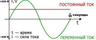
Various electrical equipment and modern electrical networks in general primarily use alternating current for their operation. Alternating current powers engines, induction furnaces, machine tools, computers, heaters, heating elements, lighting fixtures, and household appliances. It is impossible to overestimate the importance of alternating current for the modern world. However, high voltage is used to transmit electrical energy over long distances. And the equipment requires a reduced voltage for its power supply - 110, 220 or 380 volts. Therefore, after transmission over a distance, the electrical voltage must be lowered. The reduction is carried out in steps using transformers and autotransformers.
In general, transformers are step-up and step-down. Step-up transformers are installed in power generating plants, where they increase the alternating voltage received from the generator to hundreds of thousands and even millions of volts, suitable for transmission over long distances with minimal energy loss. And then this high voltage is lowered again using transformers.
A conventional power or network transformer is an electromagnetic unit, the purpose of which is to change the effective value of the alternating voltage supplied to its primary winding. A transformer in its canonical form has several windings, but at least two - primary and secondary. The turns of all windings of the transformer wrap around a common magnetic circuit - the core. The primary winding is supplied with a voltage whose value must be changed; a consumer or a network with sockets from which numerous consumers will be powered is connected to the secondary winding(s). The operation of the transformer is based on Faraday’s law of electromagnetic induction. When alternating current flows through the turns of the primary winding, an alternating electromagnetic field of this current acts in the space inside (mostly) the winding. This alternating magnetic field is capable of inducing an induced emf in the secondary winding, which covers the space of action of the magnetic flux of the primary winding. In a conventional transformer, the primary windings are galvanically isolated from the primary windings. In an autotransformer, part of the turns of the primary winding is used as a secondary winding. It is advisable to use autotransformers when the voltage needs to be reduced only slightly, not by several times, as conventional transformers do, but for example by 0.7 times.
Thus, the main difference between a transformer and an autotransformer is that in a conventional transformer the windings are electrically isolated from each other, while the windings of an autotransformer have common turns and are therefore always galvanically connected. In a transformer, each winding has at least two of its own terminals; in an autotransformer, one terminal will always be common to the primary and secondary windings.
Autotransformers are widely used in networks with voltages of more than 100 kV, since during a stepwise reduction in voltage, when it is clear that the windings of the final transformer will be galvanically isolated, the absence of galvanic isolation at the autotransformer stage is not critical. But from an economic point of view, autotransformers are much more profitable than conventional ones. They have less losses in the windings due to the smaller amount of copper in the wires than conventional transformers of similar power. The size of an autotransformer for the same power is smaller - lower costs for materials and core. Autotransformers have a higher efficiency, because only part of the magnetic flux undergoes transformation. And in general, the cost of an autotransformer is lower. The disadvantages of an autotransformer, unlike a conventional one, include the lack of galvanic isolation between the primary and secondary circuits. If the insulation is damaged for any reason, the low voltage winding will be exposed to high voltage. Therefore, autotransformers are usually not used in everyday life so as not to expose the average person to the danger of electric shock.
At voltages up to 1000 volts, autotransformers are used to regulate voltage in the form of laboratory devices - laboratory autotransformers (LATRs) and as part of electromechanical voltage stabilizers (see - Network voltage stabilizers 220V - comparison of different types, advantages and disadvantages)
A transformer usually consists of several windings (two or more) wound on a common steel core. One winding is connected to the AC source, and the other winding(s) is connected to the electrical current consumer. The operation of the device is based on the use of electromagnetic induction (Faraday's law). In other words, a change in the magnetic flux passing through the winding creates an electromotive force in this winding. In transformers operating at ultra-high frequencies, sometimes there may be no magnetic core; such devices are called air-type. In cases where it is necessary to change the voltage within small limits, an autotransformer is used.
Electrical equipment for different purposes requires different voltages to operate. For example, household equipment is designed for 220 or 110 V. Industrial equipment is usually 380 V. And since high voltage is required when transmitting electric current over long distances (to reduce the overall losses of electricity during transportation), it is used in series to power local networks decrease by steps. All these voltage transformations are carried out using transformers or their varieties - autotransformers. Transformers, depending on the needs, are step-up (increase the voltage) and step-down (lower the voltage). In both cases, the essence of the operation of this device is the same - to achieve the required voltage of electric current.
- Definition
- Difference
- Conclusions TheDifference.ru
Difference
So, the main difference between a transformer and an autotransformer is the number of windings. Transformers have two or more of them, autotransformers have one. Autotransformers are widely used in networks with voltages of 150 kV and higher, due to their lower cost than transformers and lower losses in active power windings (compared to transformers of the same power). In addition, autotransformers are much smaller in size than transformers. The main advantage of autotransformers over other types of transformers is their higher efficiency, since only part of the power is converted into them. In addition, due to lower consumption of steel for the core, copper for windings, smaller dimensions and weight, the cost of this type of transformer is significantly lower than that of other options. The disadvantage of autotransformers (in comparison with transformers) is the lack of electrical insulation between the primary and secondary windings. This is not important for industrial networks, where in any case the neutral wire must be grounded, but it is unacceptable for use in everyday life, because in case of accidents in autotransformers, the higher voltage from the primary winding may well be applied to the lower one (insulation breakdown of conductive parts). As a result, all parts of the installation will be connected to the high-voltage part, which is unacceptable according to safety rules when servicing such equipment. For domestic needs, a more reliable and safe transformer is usually used.
But violations can also occur with them, which will result in breakdown. To prevent this from happening, special protection is provided in the autotransformer. Its essence is that in case of any overload, the device gives an appropriate warning signal, and if the device fails, an automatic shutdown is triggered. Autotransformer protection is divided into several types:
Transformers are a fairly diverse group of equipment, with significant internal differences in purpose and design features. In addition, different equipment requires different voltages to operate. There are averages. Which are taken into account when drawing up a technical permit for connection. For example, household appliances are designed for 220 or even 110 V. But industrial-type equipment uses 380 V. They have their own options, lighter and less expensive. But before you decide to use it, you should know the difference between a transformer and an autotransformer.
What are both devices? ↑
Any transformer is a static type device that converts alternating current, frequency, and the number of phases. This device includes two or more windings that are wound on a single steel core. One of the windings must be connected to an alternating current source. The rest can be connected to end consumers. As a result, both electromagnetic and electrical connections are observed between them. Additionally, the winding of the autotransformer is equipped with three or more terminals, that is, it is possible to connect to different terminals and, accordingly, obtain different voltage values. The principle of operation is based on the well-known electromagnetic induction. Simply put, the magnetic flux that changes as it passes through the winding forms an electromotive force in it. This type of transformer is perfect for changing voltage in a relatively small range.
The ratio of the EMF values is expressed by the formula: E1/E2 = w1/w2 = k, where E is the EMF, w is the number of turns, k is the transformation ratio.
The operation of electrical equipment is ensured by a system of step-up and step-down transformers. The devices “differ” in a number of characteristics. Household units are designed for voltage of 110 or 220V, and household units are designed for 380V. Some of the presented devices reduce or increase voltage, others transfer electricity gradually from the substation to consumers.
Similar actions are performed by “transformers and autotransformers”. The units are characterized by some differences. However, such devices are designed to maintain the required voltage level in the network. To learn how to use such equipment correctly and safely, you need to consider their main differences.
- 1 Basic definition
- 2 Main differences
Why is it necessary to reduce the network voltage?
It is customary to transport electrical energy over long distances at maximum voltage levels. If electricity is at a household voltage level of 220 V, or even a voltage of 380 V for use at large facilities, significant losses will occur during its transportation, which will make the transmission of electrical energy costly for network enterprises. Thus, electricity is transported at high voltage, and therefore, for its use by end consumers, the voltage level of the electricity must be significantly reduced. They reduce the voltage level of electricity using special devices called transformers. Autotransformers are significantly smaller in size, they are convenient to use and easy to install, although they do not have the same high functionality that is typical for standard devices. Specialists are required to understand the types and features of transformers to organize reliable electrical systems.
It cannot be said that the only purpose of transformers is to reduce the voltage level of electrical energy. In addition to step-down equipment, which is required to supply power to end consumers, step-up devices are also used in electrical networks. Boosting devices in the circuit are required in order to transport electricity over long distances with a minimum level of losses.
Features of transformers
Any transformer is designed to change the properties and characteristics of electrical energy. This is a static device capable of converting alternating current, the number of phases in the electrical network and the frequency of electricity. A transformer can include two or more windings installed on a single steel core. Regardless of the total number of windings, at least one of them must be connected to an alternating current source. All other windings of the device can be connected to electrical energy consumers.
This design provides the necessary electrical and electromagnetic connections between the windings. Autotransformers are equipped with additional windings that have several separate terminals. In other words, such devices can be connected to different terminals, due to which different voltage parameters in the network can be provided.
Autotransformers operate on the principle of electromagnetic induction; when a magnetic flux passes through a winding, an electromotive force appears in it. This equipment is perfect for changing the characteristics of electrical energy in small ranges.
The main differences between transformers and autotransformers
The main and most important difference between the two transforming devices is the number of windings on them. Standard instruments use more windings than automatic ones, the latter usually having only one winding.
Each of these devices has its own advantages and disadvantages, which all professionals should be very familiar with. Automatic transformers are excellent for use in power supply networks with a voltage of at least 150 kV. Such devices are characterized by a relatively low cost and during their operation the level of losses on the windings will be as low as possible. Another positive feature of automatic devices is their small size. Due to the described features and partial power conversion, such devices are characterized by extremely high efficiency.
Automatic devices also have certain disadvantages when compared with standard transformers. First of all, automatic devices do not have reliable electrical insulation between the windings. This feature makes the use of autotransformers for domestic purposes extremely dangerous, although in industrial circuits where there is reliable grounding, this drawback is not particularly significant.
To summarize, we can say that standard transformers are more versatile, they are suitable for use in almost all conditions, which cannot be said about their automatic counterparts. When choosing transformer equipment, it is necessary to take into account the permissible level of voltage losses in networks.
Application of autotransformers
Unlike standard transforming equipment, automatic transformers cannot be used in all situations. Most often, such devices are used to ensure smooth regulation of voltage and current in an electrical system. By installing such equipment, it is possible to achieve the transfer of electricity in full to consumers only if the transformation coefficient is at the level of unity.
Since automatic transformers are equipped with special sectioned windings, they can be used to ensure smooth adjustment of electrical devices. It should also be noted that due to their simple design and simple installation, automatic transforming devices are easy to repair, which affects the cost of operating the entire electrical system. If the equipment fails, specialists will only need to replace the winding, which can be rewound manually with the necessary training and professional knowledge.
Autotransformer protection
If we compare the reliability and safety of operation of transformers and autotransformers, it should be noted that automatic devices do not have a rotating part, which makes them much more reliable and durable. Despite this feature, during the operation of such devices, various problems, failures and breakdowns may also arise that repairmen will have to deal with.
To reduce the likelihood of major damage, it is customary to install protection on automatic transformers. The protection works as follows: if any malfunction occurs on the device during operation, a corresponding light signal will be given. If the problem persists, the device will automatically turn off to avoid serious problems with the electrical system.
What is the difference between a transformer and an autotransformer?
To convert voltage in electrical engineering, transformers or autotransformers are used. Due to the similarity of the names of these two devices, they are often confused or equated to the same thing. However, this is not the case, although the principle of operation is similar, the design and their scope of application are fundamentally different. Therefore, let's look at the differences between a transformer and an autotransformer to understand what is the difference anyway?
Definitions
A transformer is an electromagnetic device that transmits energy through a magnetic field. It consists of two or more windings (sometimes called coils) on a steel, iron or ferrite core, depending on the number of phases, input and output voltages. Its main feature is that the primary the circuit and the secondary are not electrically connected to each other, that is, the windings do not have electrical contacts. This is called galvanic isolation. And such a connection of coils is called inductive. Below you see a conventional graphic designation of a two- and three-winding transformer on an electrical circuit diagram:
They come in step-up, step-down and isolation modes (input voltage equals output voltage). Moreover, if you apply power to the secondary winding of a step-down transformer, you will receive an increased voltage on the primary windings, and the same rule works for a step-up transformer. An autotransformer is one of the transformer options with one winding wound on a core, in principle similar to the previous case. In it, unlike ordinary trance, the primary and secondary circuits are electrically connected to each other. This means that it does not provide galvanic isolation. You can see the conventional graphic designation of the autotransformer below:
Autotransformers come with a fixed output voltage and adjustable. The latter are known to many as LATR (laboratory autotransformer). They can also be either downward or upward. In an adjustable LATR, the secondary circuit is connected to a contact sliding along the coil.
Important! Due to the lack of galvanic isolation, autotransformers, by definition, cannot be isolating, unlike conventional ones! Another difference is the number of autotransformer windings - usually it is equal to the number of phases. Accordingly, to power single-phase devices, single-winding products are used, and for three-phase devices, three-winding products are used.
Operating principle
Briefly and in simple words, let's look at how each design option works. A transformer has at least two windings - primary and secondary (or several). If the primary is connected to the network (or another source of alternating current), then the current in the primary winding creates a magnetic flux through the core, which, penetrating the turns of the secondary, induces an emf in them. The principle of operation is based on the phenomena of electromagnetic induction, in particular Faraday’s law. When current flows in the secondary winding (to the load), the current in the primary winding also changes due to mutual induction. The voltage difference between the primary and secondary windings is determined by the ratio of their turns (transformation ratio). Up/Ud=n1/n2 n1, n2 – the number of turns on the primary and secondary. Speaking about an autotransformer, it has one winding, if there are several phases, there are the same number of windings. When alternating current flows through it, the magnetic flux that arises inside it induces an emf in the same winding.
Its value is directly proportional to the number of turns. The load (secondary circuit) is connected to the tap from the turns. On a step-up autotransformer, power is supplied not to the ends of the winding, but to one of the ends and a tap from the turns, unlike a transformer.
What was shown in the diagram above.
Main differences
To make it easier for you to understand the difference between a regular transformer and an autotransformer, we have compiled their main differences in a table:
| Transformer | Autotransformer | |
| Efficiency | The efficiency of an autotransformer is greater than that of a conventional one, especially when the difference between the input and output voltage is insignificant. | |
| Number of windings | Minimum 2 or more depending on the number of phases | 1 or more, equal to the number of phases |
| Galvanic isolation | Eat | No |
| Electric shock hazard when powering household electrical appliances | With an output voltage of less than 36 Volts - small | High |
| Safety for powered devices | High | Low, if there is a break in the coil on the turns after the output to the load, the entire supply voltage will fall on it |
| Price | High, the consumption of copper and steel for cores is high, especially for three-phase transformers | Low, due to the fact that there is only 1 winding for each phase, the consumption of copper and steel is lower |
Transformers are used everywhere - from power plants and substations designed for tens and hundreds of thousands of volts, to powering small household appliances. Although power supplies have been used recently, they are also based on a generator and a transformer with a ferrite core.
Autotransformers are used in household network voltage stabilizers. LATRs are often used in laboratories when testing or repairing electronic devices. Nevertheless, they have found their application in high-voltage networks, as well as for the electrification of railways.
For example, railways use such products in 2x25 networks (two 25 kilovolts each). As in the diagram above, a 50 kV line is laid in sparsely populated areas, and 25 kV is supplied to the electric train via a contact wire from a step-down autotransformer. This reduces the number of traction substations and line losses. Now you know the fundamental difference between a transformer and an autotransformer. To reinforce the material, we recommend watching a useful video on the topic: You probably don’t know:
The structure of the technical device in question has already been discussed above. But the question arises: what magnetic materials are used to ensure its uninterrupted operation?
In the simplest case, there are two windings connected in series on a closed magnetic circuit. Depending on the connection option of the energy source and load, the autotransformer can operate as a step-up or step-down.
There is a design that implements a mechanism for manual regulation of the output voltage (Variac, LATR). Automatic control units with feedback are also used; in fact, an autotransformer with such a device can be called a voltage stabilizer.
Scope and types
transformer in tv
Household transformers protect equipment during voltage surges.
Therefore, they are used in the following devices:
- in lighting;
- oscilloscopes;
- TVs;
- radios;
- measuring devices, etc.;
Welding units that separate the power and welding networks are actively used in welding and electrothermal structures, where they successfully reduce the voltage to the required ratings.
The power grid uses oil-fired units with voltages of 6 and 10 kV.
Many automatic designs use transformers, where the voltage on the coils is non-suctional.
Kinds:
- Rotating. The signal is transmitted to objects that rotate. For example, a video recorder, where the signal is transmitted to the drum of the magnetic head assembly. Here there are 2 halves of the magnetic circuit and their rotation occurs with a minimum gap in relation to each other. Based on this, a high speed of revolutions is realized; in the contact signal method it is not considered possible to achieve such an effect.
- Peak transformer. In this option, the sinusoidal voltage is converted into spikes that have a peak shape. They are actively used in the control of thyristors, as well as electronic and semiconductor devices.
- Coordinator. Takes part in matching resistances in different intervals of the electronic circuit, while the signal shape is minimally distorted. Galvanic isolation between circuit zones is synchronously ensured.
- Dividing. Here the 2 windings are not electrically connected to each other. This scheme makes it possible to increase the safety of electrical networks. When an accidental simultaneous touch of a live part and the ground occurs, galvanic isolation of the electrical circuit is generated.
- Pulse. In this option, pulse signals are converted in a very short period of time (tens of microseconds), while the curvature of the pulse configuration is minimal.
- By voltage. Here the conversion of high voltage to low voltage occurs. This option allows you to isolate measurement and logic circuits from high voltage.
- By current. This type measures high current circuits. For example, in the designs of relay panels of electrical power systems. Therefore, fairly stringent accuracy requirements apply.
- Autotransformer. In this type, the two windings are connected directly. As a result, an electrical and electromagnetic connection is created, which explains the high efficiency of this type. The disadvantage of such a device is the lack of insulation, that is, there is no galvanic isolation.
- Power. This option is used with variable current and converts electrical energy in installations and power networks. This type is widely used on high-tension power lines (35-750 kV), city electrical networks (10 and 6 kV).
- Twin throttle. The presence of 2 equal wraps makes it possible to obtain a more effective throttle than a conventional one. They are used at the filter input in the power supply, as well as in audio equipment.
- Transfluxor. The remaining magnetization of the magnetic wire is large, which makes it possible to use it for storing information.
Operating principle of an autotransformer
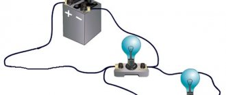
In an autotransformer, energy is transferred not only by magnetic flux, but also electrically, since the windings have a galvanic connection. The closer the transformation ratio is to 1, the less energy is transferred electromagnetically. Below you see a diagram of a step-down autotransformer, an alternating voltage source is connected to the primary winding, and a load in the form of an incandescent lamp is connected to the terminals of the secondary winding.
In idle mode, the autotransformer works like a regular transformer. When a load is connected, the alternating magnetic flux arising in the core induces an EMF in the turns of the secondary winding directed towards the EMF of the energy source. Therefore, the current flowing through the secondary winding is equal to the difference between the load current and the primary circuit current. This allows the secondary winding to be made from small diameter wire. The savings on copper are smaller, the more the transformation coefficient differs from unity.