Microcontrollers / For Beginners /
| What is needed to become a professional program developer for microcontrollers and reach a level of skill that will allow you to easily find and get a job with a high salary (the average salary of a microcontroller programmer in Russia at the beginning of 2022 is 80,000 rubles). Read more… |
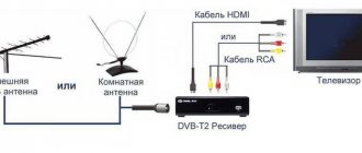
As you understand, powerful and/or high-voltage loads (such as incandescent lamps, electric motors, electric heating elements, etc.) cannot be directly connected to the output of the microcontroller. Because the microcontroller outputs:
- Not designed to operate with high voltage.
- Not designed to drive heavy loads (loads that draw a lot of current).
- They do not have galvanic isolation (sometimes this is important even when controlling a low-current load).
It follows from this that in order to control a powerful load using a microcontroller, it is necessary to use some clever methods of pairing the microcontroller outputs with the load. There are several of these methods:
- Load connection via optocoupler
- Connecting the load through a transistor.
- Connecting the load via an electromagnetic relay.
- Load connection via solid state relay.
These types of connections will be discussed in more detail in the relevant articles. And here I will only talk about the advantages and disadvantages of these methods.
Load connection via optocoupler
So, one of the simplest ways is to connect through an optocoupler (photosemistor, photothyristor, etc.).
This method is suitable for controlling active loads such as incandescent lamps, electric heaters, etc. Its advantages are the presence of galvanic isolation, relative ease of connection and low cost of optocouplers. There is, perhaps, only one serious drawback. But quite significant - when controlling an inductive load, such as electric motors, the triac/thyristor of the optocoupler can spontaneously open (without a command from the microcontroller). So for such a case, you will have to take additional measures to complicate the device on the microcontroller.
Another disadvantage is that to use an optocoupler you need to have at least a little understanding of electronics.
Load control circuit based on powerful optodinistors
Phase control method
This is the standard way to control a thyristor. It consists in choosing the moment of opening of the thyristor relative to the beginning of the phase of the current half-cycle of the supply voltage. The following figure illustrates this process:
Phase control method
The figure shows the waveform at the load for different delay times. The control algorithm is that the controller first waits for the start of the next half-cycle. Having detected the beginning of a half-cycle, the controller starts an internal timer. At the end of the delay generated by the timer, the controller outputs a trigger signal to the output that controls the thyristor regulator. The thyristor opens and voltage is supplied to the load. It is important that the control voltage is removed from the thyristor before the end of the current half-cycle. In this case, as soon as the mains voltage reaches zero, the thyristor will close and with the beginning of the next half-cycle the time counting process will repeat again. Depending on the selected delay duration, the power supplied to the load will be different. So, at a short delay time (t1), the power is maximum. At t2, exactly half of the possible power is given to the load, and at t3 the power is minimal.
Method for eliminating individual half-cycles
The main disadvantage of the previous method is the high level of electromagnetic interference emitted by the thyristor switch during operation. Such a circuit will greatly interfere with a nearby TV or radio, creating interference on the screen and in sound. The high level of interference is due to the fact that the thyristor is turned on at the moment when the instantaneous value of the mains voltage is close to its amplitude. Steep fronts have a sufficiently high voltage level and create a large amount of interference. The solution is the second regulation method. It consists in the fact that the thyristor is always switched on at the very beginning of the half-cycle, when the voltage passes through zero and, if the half-cycle is passed to the load, then the entire half-cycle is passed through. The power is adjusted by eliminating individual half-cycles. This process is shown in the following figure:
Half-cycle elimination method
In the figure we see that all half-cycles from the first to the fifth thyristor open without hindrance. Then, during the sixth half-cycle, the control signal from the thyristor is removed and no voltage is supplied to the output. At the beginning of the seventh half-cycle, the control signal is turned on again. To implement this method, entire schemes for eliminating half-cycles are being developed. For example, a sequence of ten half-cycles is taken. In order to obtain a power of 50%, five half-cycles are passed to the load, and the remaining five are not passed. Then everything is repeated every 10 half-cycles. Moreover, it is not necessary to exclude consecutive half-cycles. You can scatter the included half-cycles throughout this segment. To obtain 10% of the power out of 10, only one half-cycle will have to be left. And for 70% you need to leave 7 and exclude three. And so on...
The disadvantage of this method is that it is difficult to regulate the glow power of an electric lamp in this way. The lamp will flicker noticeably. But for adjusting the power of the heating element, this method is the most optimal.
Last update (04/30/2008)
Optodinistor control
Author Belov A.V.
04/30/2008
This article describes an electronic switch circuit based on an optodinistor, which allows the microcontroller to control a powerful load powered from a 220V network.
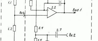
This circuit is an alternative to the circuit described in the article “Thyristor Control”. In the old version of the circuit, a powerful triac was used to switch the load, and a low-power optodinistor was used to decouple the 220V controlled circuits and the low-voltage circuits of the microcontroller. The new version of the circuit uses a powerful optodinistor to control the load, which replaces both of the devices listed above. Below is a diagram of such a device:
Power supply diagram
Author Belov A.V.
04/30/2008
This article discusses a regulated power supply circuit that can be used to power a simple microprocessor device.
As you know, to power digital microcircuits you need a stabilized voltage of 5V. Note that modern microcontrollers are capable of operating in a wide range of supply voltages. Typically 3 to 6 volts. The main requirement is that the voltage be stabilized. That is, it did not change when the load changed. However, usually any microprocessor device, in addition to the microcontroller itself, contains a number of other microcircuits, which are usually more demanding on the supply voltage. Therefore, it is most correct, unless there are any special reasons, to choose a supply voltage of +5V. This supply voltage is widely used in electronic technology. Therefore, the industry has long established the production of special microcircuits - voltage stabilizers. For most applications, the 7905 chip or its domestic analog KREN5 is suitable. The figure below shows a diagram of a power supply that is designed to power almost any microcontroller-based device.
Power supply diagram
Transformer T1 lowers the mains voltage to the required value (approximately 8...9 volts). Rectifier VD1 straightens it. Pre-filter C1 smoothes out the ripples of the rectified voltage and, as a result, a constant unstabilized voltage of approximately 12 V is supplied to the input of the stabilizer DA1. From the output of the stabilizer, a stabilized voltage of 5V is supplied to the output (to power the digital circuits of the microcontroller device. An unstabilized voltage of +12V is also supplied to power some circuits of a microcontroller device. Usually these are power circuits that do not require voltage stabilization: LEDs, relays, etc. Connecting such circuits before the stabilizer significantly relieves the load on the DA1 microcircuit, facilitates its thermal conditions, increases reliability and increases efficiency. Additional filter C2, C3 serves to suppress power supply interference.Moreover, the electrolyte C3 serves to suppress low-frequency interference, and the ceramic capacitor C2 suppresses high-frequency interference.
In addition to the power circuits themselves, the above circuit contains special circuits that allow you to receive a signal synchronous with the frequency of the mains voltage. Such a signal can be supplied to a comparator, which is part of many microcontrollers and allows you to implement control algorithms for thyristor or optodinistor switches for smooth power control on the load. In such algorithms, the processor counts the required delay from the beginning of the current half-cycle of the mains voltage and, after this delay, turns on the thyristor. At the end of the half-cycle, when the instantaneous voltage passes through zero, the thyristor closes and the microcontroller counts the next delay. By changing the delay time, you can change the duration of the pulses supplied to the load and thereby change the power supplied to this load.
You can read more about this in the article “Control of a thyristor” and in the article “Control of an optodinistor”.
Connecting LEDs
Author Belov A.V.
05/01/2008
This article explains how to connect single LED indicators to a microcontroller.
No microcontroller-based device is complete without indicator lights. It is most convenient to use LEDs as single light emitters. Modern microcontrollers (in particular the AVR series microcontrollers) have quite powerful output circuits. They are designed for output currents up to 40 mA. This is quite enough to directly connect one low-power LED. The following figure shows how you can connect an LED to the output of a microcontroller.
Direct LED connection
A simple low-power LED indicator is the most common indication method. These are the indicators we see on the vast majority of structures. However, sometimes it is necessary to connect more powerful LEDs to the microcontroller. These are high-brightness LEDs or large-area LEDs. In the case when the LED current consumption exceeds 40 mA, an electronic switch on a transistor is used. Below is a diagram of such a connection.
Connection using an electronic key
When using the KT315 transistor, you can connect an LED with a current consumption of up to 100 mA. If you need to connect an LED with an even higher current consumption, then you need to select another, more powerful transistor.
Connecting buttons
Author Belov A.V.
05/01/2008
This article covers the issues of connecting various buttons and keys to the microcontroller.
Rice. 1.
Almost no microprocessor system can do without buttons, keys, end contacts and similar switching elements. Any similar switching device is simply a pair of contacts that close when a key (button) is pressed or other mechanical action occurs. For example, when the limit switch of a controlled mechanism is triggered. Therefore, connecting any of the above devices comes down to connecting a pair of contacts to the microcontroller. The AVR series microcontrollers are quite well suited for working with buttons. Each of the pins of each port has special means to facilitate the connection of external contacts.
Figure 1 shows a typical way to connect a pair of pins to a microcontroller port. Let's take a closer look at the operating principle of this circuit. But first we must remember that any of the pins of any port can operate in one of two modes: either as an input or as an output. Naturally, in our case, the corresponding pin must be switched to input mode. In this mode, it is possible to programmatically, if necessary, connect an internal load resistor to any external line. In Figure 1, this resistor is designated R. This resistor is specially introduced in order to work with external contacts. When creating a program for all inputs to which pins are connected, be sure to provide commands that turn on this resistor. If the input is intended for other purposes, then most likely the resistor needs to be disconnected. An electronic key that programmatically turns on and off the internal load resistor is conventionally shown in Figure 1 and designated as K.
And so, the port output is programmed as an input, the internal load resistor is turned on. If the external contacts K1 are open, then there is a voltage at the input close to the supply voltage, which is supplied through resistor R. When reading information from the port, this bit will be a logical one. If the contacts are closed, the port line will be shorted to the common wire. The input voltage will become zero. When reading information, a zero will appear in this port bit. Thus, by reading information from the port and analyzing the value of the corresponding bit, the microcontroller can always determine whether the contacts are closed or not. If the discharge is zero, the contacts are closed, if one, the contacts are open.
In the above manner, you can connect a separate pair of contacts, if desired, to all pins of all ports. However, this approach cannot be called rational. In addition to keys, other devices must be connected to the microcontroller ports: indicators, relays, sensors, serial communication channels and much more. Therefore, to save pins and simplify the circuit, key matrices are used. A diagram of a typical 16-key matrix is shown in Figure 2.
Rice. 2.
To connect the matrix, the entire PB port of the microcontroller and two more lines of the PD port are used. As can be seen from the diagram, each of the pins of the PB port is connected to two buttons at once. For example, pin PB0 is connected to button S1 and S9. Pin PB1 to S2 and S10 and so on. The second contact of each button is connected to one of the lines PD5 or PD6. As a result, a matrix is formed. It resembles a lattice. Two vertical wires and eight horizontal. A button is inserted at each intersection of these wires.
How does this matrix work? For proper operation, all pins of the PB port must be switched to input mode and an internal load resistor must be turned on for each of these inputs. And two pins of the PD port (PD5 and PD6) need to be switched to output mode. In order to read the state of the buttons, the microcontroller must first apply a logical zero signal to output PD6, and a logical one signal to output PD5. Then it should read the byte from the PB port. This byte will contain information about the state of the S1...S8 buttons. Each bit will be responsible for its own button. Bit zero (PB0) for button S1, bit one (PB1) for button S2, etc. If the button is pressed, then the corresponding digit will be zero, if not pressed, the corresponding digit will be one. After analyzing the pressing of the first half of the buttons, the microcontroller should set the PD5 output to a logical zero, and the PD6 output to a one. And again read the byte from the PB port. Now this byte will contain information about the state of the S9...S16 buttons. By polling the first or second half of the buttons in this way, the microcontroller can respond to pressing each of the buttons separately.
The matrix described above can be easily expanded. You can take not two vertical lines, but three, four, and so on. For this microcontroller, the maximum possible matrix has dimensions of 7X8. Since the PD port has only seven lines. The total number of buttons will be 56.
Last update (05/01/2008)
Control of LCD indicators
Author Belov A.V.
05/02/2008
This article discusses an example of connecting a liquid crystal display (abbreviated LCD or LCD) to a microcontroller.
Today on the electronic components market you can find a huge number of indicators from different companies and modifications. Each indicator has its own characteristics, its own internal architecture and its own interface for connecting to a microcontroller. However, the general connection principles are approximately the same. Let us immediately note that all LCDs can be divided into indicators with a built-in controller and simple indicators without a microcontroller. Indicators with a microcontroller are more preferable for independent use. The built-in microcontroller already contains complex programs that perform most of the operations to display an image on the indicator and take into account all the specific features of this particular indicator panel. And the communication interface of the built-in controller is usually not at all complicated and makes it easy to connect it to any universal controller. Let's take, for example, a Russian-made microcontroller MT-10T7-7. This is a simple indicator, the display of which is a line of ten seven-segment symbols. The supply voltage of such an indicator is from 3 to 5 volts. Current consumption is 30 µA. Overall dimensions 66 X 31.5 X 9.5 mm. The connection diagram of such an indicator to the microcontroller is shown in Figure 1.
Rice. 1. Connecting the LCD to the microcontroller
The PB port is used to control the indicator. Lines PB0...PB3 form the data/address bus. And line PB4 is used to transmit a recording signal to the indicator. Output PB6 is used for address/data selection. Control commands are transmitted to the indicator as follows. First we need to pass the address of the bit where we want to write the code of the next symbol to be output. An address consists of a single four-bit binary number. The digits are numbered from left to right. The leftmost (most significant) bit has address 0 (00002). The next bit has address 1 (00012). The last, rightmost, tenth digit has address 9 (10012). In order to write an address to the indicator controller, it is necessary that a logical zero signal be present at its A0. The address value is set at outputs PB0…PB3. And then a single signal is briefly supplied to the PB4 output, which is supplied to the WR1 input of the indicator. At the edge of this pulse, the address is written into the indicator and stored in its internal memory. Now, if a byte of data is written to the indicator, it will go to exactly this address.
The data byte determines the character image that will be displayed in the corresponding digit of the indicator. Each bit of this byte is responsible for its own segment in the seven-segment field. The eighth bit is responsible for highlighting the decimal point. To transmit a data byte, a logical one signal must be present at input A0, and therefore at output PB6. A byte of data is transmitted to the indicator in two steps. First, the least significant nibble is set at pins PB0...PB3. Based on the signal at WR1, it is recorded in the indicator’s memory. Then, at the same outputs (PB0...PB3), the most significant nibble is set and also written to WR1 by the signal. After writing the second (most significant) nibble, the image appears in the corresponding bit of the indicator, and the address in the internal memory of the indicator automatically increases by one. Thus, to write data to the next bit of the indicator, you no longer need to transfer the address to it. The entire process of writing the address and data into the indicator is shown in Figure 2.
Rice. 2. Diagram of the indicator interface operation
This figure shows two options for working with the indicator. Record one familiarity and record several familiarities in a row. Variable resistor R1 (see diagram in Fig. 1) is designed to adjust the contrast of the display. In order for the image on the indicator to be clearly visible, you need to set the most suitable contrast while observing the image on the indicator screen. For different illumination and different viewing angles, the regulator knob will have to be set to different positions. A clearly visible image in others may become completely invisible under changed viewing conditions. To see it you need to turn the regulator knob in different directions.
In conclusion, I would like to note that these particular port pins for controlling the indicator were chosen absolutely arbitrarily. In this case, the author was guided by the convenience of the printed circuit board layout. You can choose any other pins and even another input/output port of the microcontroller.
Last update (05/01/2008)
Encoder connection
Author Belov A.V.
05/04/2008
In this article, you will learn what an encoder is, how it differs from a variable resistor, and how it helps you enter information into a microcontroller by simply turning a knob.
In connection with the total transition to microprocessor control of household and other electronic devices, the control elements used in these devices have also changed. If previously, in order to adjust the volume of a radio or TV, you had to simply turn the corresponding knob, now you are often forced to use two buttons: “Volume +” and “Volume -“. What if you need to adjust more than just the volume? For many users this is simply not convenient. In addition, the efficiency of adjustment suffers. By pressing the volume down button, you still need to wait a while until the volume reaches the desired level. And all this time you have to suffer from loud sound. To combine the advantages of traditional controllers without losing the new opportunities that microcontrollers give us, a new information input device called an encoder is designed. In appearance and installation dimensions, the encoder is very similar to a conventional variable resistor that was used in traditional analog devices. But in terms of internal structure, it is radically different. The encoder, just like the resistor, has a protruding axis, on which you can put the same handle that is usually put on the resistor. Rotating the encoder handle causes it to generate a sequence of pulses, which then go to the microcontroller and give it information about how much to decrease or increase a particular value. For example, how much should you increase or decrease the signal volume, etc. Moreover, the design of the encoder is such that the microcontroller can distinguish not only the amount by which the parameter needs to be changed, but also the direction of this change. This allows, for example, when rotating the encoder axis in one direction, to increase the volume, and when rotating in the other, to decrease it.
Rice. 1. Operating principle of the encoder
Let's look at how the encoder works. Figure 1 shows the design of a simple mechanical encoder. As can be seen from the figure, the basis of the encoder is a disk made of insulating material mounted on an axis, onto which the handle is mounted to rotate it. Special slots are evenly spaced around the perimeter of the disk. The slots divide the entire circle into several (usually 6-8) equal sectors. Moreover, the width of the slots is equal to the width of the spaces between them. In addition, there are two groups of contacts that are installed in such a way that when the disk rotates, they either close when they fall into the slot, or open in the space between the slots. The location of these pairs of contacts relative to the slots is very important. The contacts are located in such a way that at the moment when one pair is on the edge of a slot, the second pair of contacts is exactly in the middle between two adjacent slots. This is exactly the arrangement shown in the figure. As a result, the following order of closing/opening contacts is implemented:
The first group of contacts closes
The second group of contacts closes
The first group of contacts opens
The second group of contacts opens
5. Everything repeats from the beginning.
Rice. 2. Encoder circuit Fig. 3. Operation diagram
Figure 2 shows the internal electrical circuit of a simple mechanical encoder. The encoder has only three pins (which makes it even more similar to a variable resistor). The bottom pin in the diagram is common to both pairs of contacts. As a result, when we rotate the encoder handle, we will receive two sequences of pulses at the output. With uniform rotation in one direction, these will be two meanders, out of phase by 90 degrees. For clarity, this process is shown in Figure 3. I hope it is clear how the microcontroller determines the angle of rotation of the encoder axis. It simply counts the number of pulses. Moreover, it is possible to count impulses coming from any of the group of contacts. The main focus is how to determine the rotation directions. This is where the sequence of closing and opening contacts helps. When the encoder axis rotates to one side, each time the first group of contacts moves from a closed state to an open state, the second group of contacts becomes closed. Moreover, the moment of transition of the first group occurs precisely in the middle of the time period when the second group is closed. That is, the chatter has already ended and all transient processes have subsided. When rotating in the other direction, the order of opening and closing is reversed. Therefore, at the moment when the first group of contacts goes from a closed state to an open state, the second group is always open. It is by this fact that the microcontroller determines the direction of rotation.
Rice. 4. Connection diagram of the encoder to the microcontroller
Figure 4 shows a diagram of connecting the encoder to the microcontroller. The encoder contacts are connected in the same way as a simple separate button is connected (see the article “Connecting buttons”). Port lines PD2 and PD3 must be configured as inputs and the internal pull-up resistor on both inputs must be enabled. For more information about setting up port lines and internal load resistors, see the article “Connecting Buttons” mentioned above. The common output of the encoder, as can be seen from the diagram, is connected to the common wire of the entire device.
The program for processing the signal from the encoder is extremely simple. Please note that in the diagram (Fig. 4) lines PD2 and PD3 are selected for connecting the encoder. And this is no coincidence. In the ATtiny2313 microcontroller, an alternative function of these pins is the function of the external interrupt inputs INT0 and INT1. To work with the encoder, one of these interrupts is used. For example, you can use an interrupt on the external input INT0. That is, at the PD2 input (pin 6). What does the program consist of? Well, first of all, you first need to enable the INT0 interrupt. Moreover, it is necessary to select a mode when the interruption occurs at the edge (or fall) of the pulse at this input. Well, then we also need a simple subroutine for processing this interrupt. This subroutine should simply check the value of the PD3 port line and, depending on whether it is zero or one, decrease or increase the adjustable value.
Let's look at this in more detail. Let's assume that we have chosen the pulse edge interrupt mode. Let's imagine that the controller is executing a main program that is not associated with the encoder. At some point the user rotates the encoder handle, for example, to the left. The contacts begin to close and open. At the edge of the pulse at the INT0 input in the microcontroller, an interrupt is called. This means that the main program is temporarily interrupted and the controller moves to the interrupt handling routine. This routine reads information from the PD port and evaluates the contents of the PD3 bit. Since the encoder handle was turned (we agreed) to the right, the microcontroller will detect a logical one in this bit. Having detected a unit, the interrupt processing subroutine increases the value of a special cell where the code corresponding to the current volume is stored. The code is incremented by one. After this, the subroutine finishes its work. The microcontroller goes back to executing its main program. If rotation in the same direction continues, then at the edge of the next pulse an interruption will again be caused at INT0 and the volume value will again increase by one. And so on until the rotation of the encoder handle stops or the volume value overflows. The routine should check this value and not increase the volume if it has reached the maximum.
If the encoder rotor is rotated in the other direction, then the same interrupt processing procedure, called at the edge of the signal at the NT0 input, will detect a logical zero value at the PD3 input. Having detected this zero, the subroutine must decrease the code value in the volume cell by one. If the rotation continues, then at the edge of each pulse at the INT0 input this interrupt will be called and each time the volume value will decrease. And in this case, the program must now control the minimum volume value. And when zero is reached, the program should no longer perform the subtraction procedure.
So far we have talked about a simple mechanical encoder. But the presence of mechanical contacts is always associated with phenomena such as chattering, as well as interference caused by poor contact due to clogging or wear. All this leads to low reliability of the mechanical encoder. Therefore, recently optoelectric encoders have become increasingly widespread. An optoelectric encoder uses optocouplers instead of mechanical contacts: LED-photodiode. Such an encoder requires additional external power, so it has one more output - a power output. Such encoders are usually powered from a stabilized +5V source and produce output signals close to standard logical levels. In this regard, there is no need to include internal load resistors for those microcontroller inputs to which such an encoder is connected. Otherwise, working with optoelectronic encoders is similar to working with simple mechanical models. Unfortunately, the use of optoelectronic encoders is limited by their high cost.
Last update (05/04/2008)
Practical examples of using USB-AVR
The USB-AVR project has appealed to many amateur designers from all over the world. The Objective development company on its website encourages everyone who has developed their own design using their technology to send a description of it or a link to a site with such a description and willingly places all these links on its website.
THAT. The fact that the project involves representatives from different countries has led to different descriptions being given in different languages. Mainly in English, German, Italian. Unfortunately, there is not a single project in Russian yet. However, our website plans to translate descriptions of the most interesting projects.
The list of projects completed using USB-AVR is located at https://www.obdev.at/products/avrusb/projects.html The list is divided into categories:
Interfaces and adapters
This section lists examples of adapters that convert the USB standard to other standard types of interfaces. The following examples are given:
USB to uDMX converter. The uDMX standard is an extension of the DMX standard and differs from the latter in the presence of power. The DMX channel is designed to control lighting devices and various stage effects.
Miniature I2C bus adapter. For example, used in conjunction with the DS1621 temperature sensor.
USB – LPT adapter.
1Next ⇒
Recommended pages:
Connecting a load via a transistor
It's also quite simple to do. The cost of conventional transistors is also relatively low. That's a plus.
Cons - you can only control a DC load (we are talking about cheap bipolar transistors). Moreover, the load voltage should also be as low as possible. Because high-voltage transistors are no longer very cheap (and some are very expensive).
Another drawback is the lack of galvanic isolation between the load and the microcontroller output.
And, just as in the case of an optocoupler, you need to have at least a little understanding of electronics in order to select the right transistor and calculate the circuit diagram for switching on the transistor itself and additional resistors.
§ 38. Using PWM. Connecting field effect transistors. |
| Kiselev Roman, June 2007 |
| Article updated May 26, 2014 |
| Files for the article |
| In this article we will look at the issues of adjusting the power of various devices connected through a field-effect transistor to the MK using pulse width modulation (PWM). |
First, a little theory. PWM is a method widely used in electronics to regulate the power of a wide variety of devices. Where else has it not found application! The method involves briefly turning on the device (for a fraction of a millisecond), and then turning it off for a certain point in time. This on-off cycle is continuously repeated. Consider the diagram below.
The diagram shows the dependence of load voltage on time. The gray area is the area when the PWM controlled device was turned on. The energy released can be considered proportional to the area of this region. The ratio of the pulse repetition period (T) to their duration (AC) is called duty cycle
.
The reciprocal of the duty cycle is called duty cycle
. Judging by the diagram, the duty cycle is greatest in the middle of the diagram. This means that in this section the least amount of energy was released at the load per unit time. I hope this is all clear. But the question arises: why is PWM so good? Why not use a device that can change resistance (variable resistor or transistor) to regulate power? Let's consider two seemingly equivalent circuits.
If you change the resistance of the resistor, as shown in the graph in the center, and apply the PWM sequence shown in the diagram to the key element of the right circuit, then the light bulbs will shine the same at any time (UL is the voltage across the light bulb). But in the right circuit, energy will be released only in the light bulb, and in the left circuit, both in the light bulb and in the resistor (or transistor, which can successfully replace it). The resistor will heat up, and perhaps no worse than a light bulb. Therefore, when asked which scheme is more rational, I think anyone will answer that it is the right one. It is called pulsed, and the left circuit is called linear. When working with powerful high-current electronics, they always give preference to pulsed elements and methods. Linear ones are used only where low powers and low currents are controlled. Moreover, in digital electronics, where there are only two states - “on” and “off”, PWM is much easier to implement. This is what we will do in this article.
To do this, we need very little - a field-effect transistor, which will work as a key for us (in switching mode). A field-effect transistor is preferable because its gate is isolated from the power circuit and is controlled by an electric field, and the control current reaches microamps. This allows, using one or two transistors, to control with their help a load of enormous power (up to tens of amperes and tens of hundreds of volts), without loading the MK. Wonderful, powerful and inexpensive (10 - 30 rubles) transistors are produced by International Rectifier. They are called IRFxxxx, where xxxx is a three or four digit number. I used IRF7311 in my development board. Others similar to it are also suitable: IRF7341, IRF7103 IRF7301, IRF7343, IRF7401, IRF7403, IRF7413... These transistors are controlled by the logical level of +5 V, i.e. our MK will be enough to fully open them. They, in turn, can control voltages from 20 V (all) to 50 V (IRF7103, IRF7341) and through them it will be possible to open and close more powerful transistors with a sufficiently high control voltage, for example, IRF530. Thus, it is possible to assemble a very powerful high-speed cascade using field-effect transistors, capable of smoothly changing the power at the load using PWM, switching currents of tens of amperes. Taking into account also the fact that field-effect transistors can be connected in parallel (unlike bipolar ones), it is possible to obtain an even more powerful cascade of hundreds of amperes.
So, let's say you decide to buy the IRF7311. If you open its Datasheet (available in the files for the article), you find out the following: this is a tiny microcircuit in an SO-8 package, inside of which there are two field-effect transistors with an N-type induced channel and built-in Schottky diodes. This means that in order to open the transistor, a control voltage of +5 V must be applied to the gate G (Gate) relative to the source S (Source). Then, if a switched voltage was applied “plus” to the drain D (Drain) and “minus” to the source, then a fairly strong current (up to 6 A) will flow from D to S. The presence of a Schottky diode allows, without fear of EMF self-induction, use these transistors to control electric motors. Below is the pinout of the transistor and its appearance:
There should be a point on the top of the body in the corner, the same as in the picture. It stands next to “leg” 1. By the way, for all microcircuits, the “legs” are numbered starting from a similar mark counterclockwise, when viewed from above - in case someone doesn’t know... If you bought a field-effect transistor with a P-channel, it’s okay. Then you will have to apply a “minus” to G (relative to S) to turn it on and change the load polarity. That is, for any field-effect transistor with an induced gate, you need to supply current against the arrow located between the gate and the diode, and connect the load so that the current flows through it in the direction opposite to the built-in diode. That's all.
Let us now attach our transistor IRF7311 with a gate to the 21 “legs” of the MK (PD7, OC2
) and the source to the “ground”. We connect the “plus” of an external power source (up to 20 V) to its drain, and connect a load, for example, a light bulb or a DC electric motor, between its “minus” and the source.
When I assembled everything, it turned out like this (although the wires are not visible, the light bulb is connected):
All that remains is to figure out how the MK implements PWM and write a program. As mentioned earlier, our MK has 3 timers, and all of them can operate in PWM mode. Timer1 is the most sophisticated and can output PWM on two MK pins at once. But we will not go into details and complications that are unnecessary for us for now and will consider working with PWM using the example of timer 2.
There are two modes of operation of the timer as a PWM modulator. These are Fast PWM (fast PWM) and Phase correct PWM (PWM with phase correction). Let's look at both modes in the following diagrams:
The operating mode is determined by the contents of the WGM (Waveform Generation Mode) bits in the TCCR2 register. The Datasheet says that for PWM with phase correction you need to set WGM20 to one, and for fast PWM WGM20 and WGM21. How are these modes different? In fast mode, the state of the “leg” of OC2 changes at the moments when the counting register TCNT2 and the comparison register OCR2 coincide (green arrow), as well as at the moment the timer is reset (blue arrow). In this case, the middle of the pulse (orange) seems to shift to the left, the phase of the pulse changes . In the phase correction mode, this phenomenon is not observed. In this mode, the timer, having counted to the maximum (up to 255), begins counting in the other direction. When the TCNT2 and OCR2 registers coincide, the state of the OC2 pin changes. In this case, the center of the pulse does not shift anywhere. This mode has half the frequency of the fast mode, but the manufacturer claims that it is better suited for controlling electric motors (most likely stepper ones). Fast mode can be used in any other cases. All other timers work in the PWM mode in the same way; timer1 also allows you to change the PWM period in an arbitrary way, but I think this is of no use to us.
Everything seems to be clear with the theory now.
Let's open IAR, create a new project, type the following code: #include
“iom16.h” unsigned char pwm = 1;
unsigned char inc = 1; // inc = 0 — decrease, inc = 1 — increase brightness void
timer2_init() { OCR2 = 1;
//PWM almost off // Fast PWM, switch OC2 (PD7), increase the timer every 64 clock cycles
TCCR2 |= (1 void timer1_init() { OCR1A = 43200;
// Interrupt 32 times per second
TCCR1A = 0;
// CTC mode , increment the timer every 8 clock cycles
TCCR1B |= (1 // Interrupt on coincidence A of timer1 TIMSK |= (1 //Enable interrupts }
void
io_init()
//Initialize I/O ports
{ DDRD = (1 void main () { timer2_init (); timer1_init(); io_init(); while(1) { } }
// Causes the lamp to fade on and off once every 8 seconds #pragma
vector = TIMER1_COMPA_vect
__interrupt void
PWM_change() {
if
(inc == 1) {
if
(pwm // Increase the brightness of the lamp until we reach the maximum OCR2 = pwm; }
else
{ inc = 0; } }
else
{
if
(pwm > 1) { pwm—;
// Decrease the brightness of the lamp until we reach the minimum
OCR2 = pwm ; }
else
{ inc = 1; } } }
The timer2_init() function is used by us to enable the timer in PWM mode. The timer will increase the counting register every 64 clock cycles, operate in Fast PWM mode, changing the state of OS2 in a non-inverted manner (bits COM20, COM21). Yes, I forgot to say. These bits are responsible for the behavior of the OS2 “leg” to which the transistor is connected. The mode can be inverted or non-inverted. To understand this, look at the diagram above. There is a graph of the state of OS2 (non-inverted output) and OS2 with a line (inverted output). If both bits are set to 1, the mode will be inverted. There is one pitfall when working with PWM and using transistors: not all transistors can change their state very quickly. Some may require tens to hundreds of nanoseconds (like ours), while others may require microseconds and tens of microseconds. Therefore, I do not recommend using it at a high frequency without studying the documentation for the transistor - a large load at a high PWM frequency can burn it out.
timer1_init() turns on timer2 and causes it to do 32 interrupts per second. When an interrupt occurs, the OCR2 register changes and, accordingly, the brightness of the lamp. Thus, the lamp will smoothly light up and go out smoothly once every 8 seconds. Instead of a timer, you can connect buttons and change the brightness when they are pressed. But for clarity, everything will happen automatically.
Let's save this file in the folder with the project, add it to the project, set the project options as written in article 1, but you can now leave optimization on. The fact is that in the first article we created a delay using a loop. It is illiterate to do this from a programming point of view, and to increase the speed of the program the compiler throws out such loops. Now we use the hardware built into the MK, which does not reduce performance and speed. Therefore, optimization will not do anything bad.
Select Release, press F7, the program compiles. Launch AVReal, flash the MK. By the way, perhaps you had a question: is it possible to reflash the MK an infinite number of times? It turns out not. Only 10,000 times (at least). Therefore, I think there is absolutely no need to worry about this. After all this has been done, you can check the device.
IMPORTANT!!!
First you need to supply power to the MK, make sure that the transistor is connected to the MK, and only then supply power to the circuit with the lamp (motor) and the field-effect transistor. Otherwise you may burn out the transistor. The fact is that when turned off, the “legs” of the MK “dangle in the air” - they are not connected to anything, and interference occurs on them. These weak interferences are enough to partially open a very sensitive field-effect transistor. Then its resistance between drain and source will drop from several MOhms to several Ohms or fractions of Ohms and a large current will flow through it to the lamp. But the transistor will not open completely, because for this you need to apply not 1-3 V interference to the gate, but a stable 5 V, and its resistance will be much greater than the minimum (for IRF7311 this is 0.029 Ohm). This will cause a lot of heat to be generated on it, and it will smoke and maybe burn. Although, of course, it all depends on the power of the lamp or motor.
After turning on all parts of this device, you should see a picture similar to the one below. There is also an ammeter drawn there, showing the current strength in the lamp.
Instead of our circuit with a transistor and a lamp, you can simply connect an LED to pin OC2. It will smoothly change its brightness. But this, of course, is no longer so interesting.
© Kiselev Roman June 2007 https://www.kernelchip.ru
Load connection via electromagnetic relay
Connecting an electromagnetic relay is as easy as shelling pears. But this is only at first glance. In fact, there are also features that you need to know (I’ll tell you about them in the corresponding article). Otherwise, you can simply damage the output of the microcontroller.
Advantages of an electromagnetic relay:
- Low price.
- You can control a load of almost any power and voltage.
- Both DC and AC loads can be controlled.
- You can control both active and inductive loads without any additional tricks.
- There is a galvanic isolation between the microcontroller output and the load.
- No special knowledge of electronics is required to select a relay for the load.
Flaws:
- Additional measures must be taken to protect the microcontroller output.
- Relatively low speed (the relay switches much slower than semiconductor devices - sometimes this is important).
- Large dimensions and weight. Although modern relays are quite miniature, their size and weight are still larger than the size of semiconductor devices.
- Relatively low resource. Since the relay has contacts, the relay life is lower than that of semiconductors. Due to sparking, contacts fail faster. Although, as practice shows, high-quality relays can operate for decades without breakdowns.
Connecting the load to Arduino
Many beginners, after a few simple experiments with programmable Arduino microcontrollers, try to implement their own ideas, but are faced with a fairly common problem - connecting the load.
The fact is that at the Arduino outputs you can only get a voltage of 5 V (this is the logical one level). In this case, the current strength will be no more than 40 mA. Such parameters may not be sufficient for many external circuits and components. For example, 40 mA will not make most electric motors work, even those powered by 5 V.
Therefore, below we will consider options for connecting various types of loads.
The basic principle is to start/stop the external unit using the “one-zero” logical levels at the Arduino output. And it is best to provide protection for the microcontroller from voltage surges from the connected circuit.
Connecting weak loads
The simplest example is an LED. Most of these diodes have a current limit of 20 mA (0.02A). Therefore, it is best to connect them to Arduino through a current-limiting resistor. We looked at how to calculate it in a separate article; just in case, let’s recall the formula:
R=U/I
Here R is the resistance of the section of the circuit that includes both the limiting resistor and the diode itself (their resistances are added together). But since the diode’s own resistance is negligible, it can simply be ignored in this problem. Then we get:
Rolim = 5 V / 0.02 A = 250 Ohm.
That is, when a resistor with a value of over 250 Ohms is connected to the power circuit, we will get a current drop below 0.02 A (which is what is needed for an LED).
Similarly, you can calculate the current-limiting resistor for other elements.
A typical inclusion of low-power elements using the same LED as an example can be seen below.
Rice. 1. Typical inclusion of low-power elements using the example of an LED
Some models of Arduino boards can activate the built-in current limiting system, then the resistor may not even be needed.
Connecting high-power DC loads
Here it is necessary to stipulate separately that the external circuit must be powered from a different current/voltage source that corresponds to the nature of consumption.
Arduino can be connected to the control circuit through an intermediary, for example, through a transistor or similar circuit/element. Let's start with simple bipolar transistors.
Via bipolar transistor
The classic connection diagram will look like this.
Rice. 2. Classic switching circuit via a bipolar transistor
The value of the resistor connected to the base is given as an example. In fact, its value must be calculated in accordance with the performance characteristics of the transistor (the input voltage level depends on the gain in saturation mode and the supply voltage in the controlled circuit).
Almost any npn is suitable for the role of a transistor.
This circuit is easy to implement and affordable, but is not suitable for driving circuits with very powerful loads.
The alternative is below.
Via field effect transistor
Indeed, power circuits can be connected to Arduino via field devices.
A typical connection diagram looks like this.
Rice. 3. Classic connection circuit via a field-effect transistor
It is not worth using field-effect transistors with a low load, since, firstly, they are slow to switch, and secondly, they will get quite hot.
When connected to the gate, the same limiting resistor is used, which must be correctly calculated based on the power parameters and the characteristics of the field device itself.
And the second (10K) is used to protect the microcontroller itself and eliminate interference in the operation of the transistor (excludes the Z-state).
In the case of connecting motors or other reactive loads without protection, it is best to provide for reverse breakdown and install a diode. For example, like this. Despite the fact that diodes are often already built into modern field-effect transistors, in reality they do not always cope with the task.
Rice. 4. Inductive load
To increase the “controllability” of the circuit, it is best to choose mosfets marked “Logic Level” (they are designed to work with digital logic levels).
Through Darlington transistors
What is called an “out-of-the-box solution”. In radio stores you can find ready-made chips such as ULN2003, which are a set of independent composite Darlington transistors. The control scheme is implemented very simply.
Rice. 5. Control circuit
Here, each Arduino output controls a separate composite transistor (the output is strictly opposite). If necessary, the transistors can be connected in parallel (each “pulls” a load of 500 mA).
Via opto-relay
This is an almost ideal solution, devoid of many disadvantages associated with other methods.
Solid state relays provide complete galvanic isolation of the control circuit and the main circuit, they do not have any mechanical parts, they allow you to work with high currents, etc.
The connection diagram for the load with the opto-relay will look like this.
Rice. 6. Load connection diagram with opto-relay
The resistor in front of the relay is responsible for limiting the current. It is calculated as in the previous examples.
An opto-relay is not suitable only for cases of controlling “fast” circuits.
Other methods
Above we have outlined only the main methods used. In fact, there are many other methods for connecting powerful loads to Arduino and other microcontrollers:
1.Through semistors (triacs)
Rice. 7. Connecting powerful loads to Arduino and other microcontrollers via semistors
2.Through classic relays (another intermediary is required to control the relay itself)
Rice. 8. Connecting powerful loads to Arduino and other microcontrollers via classic relays
3.Switching with simultaneous stabilization
Rice. 9. Switching with simultaneous stabilization
4.Short circuit protected driver
Rice. 10. Short circuit proof driver
Author: RadioRadar
Load connection via solid state relay
A solid-state relay is a semiconductor device that combines, for example, a phototriac and all the wiring necessary to control it. That is, a solid-state relay can simply be connected to the output of the microcontroller, without worrying about what resistance the quenching resistors, etc. should have.
However, solid state relays are more difficult to use than conventional relays. Because solid-state relays have quite a lot of different characteristics that need to be understood. However, it is not difficult to study this topic.
A solid-state relay has perhaps only one drawback: its high price. A solid-state relay, as a rule, costs 5...10 times more than a conventional electromagnetic relay (that is, hundreds and thousands of rubles apiece).
Electronics for everyone
What kind of load are we talking about? Yes, about any - relays, light bulbs, solenoids, motors, several LEDs at once or a heavy-duty power LED spotlight. In short, anything that consumes more than 15mA and/or requires a supply voltage of more than 5 volts.
Take, for example, a relay. Let it be BS-115C. The winding current is about 80mA, the winding voltage is 12 volts. Maximum contact voltage 250V and 10A.
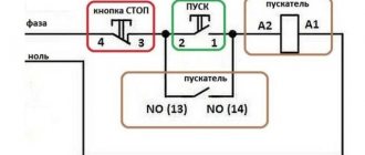
Connecting a relay to a microcontroller is a task that has arisen for almost everyone. One problem is that the microcontroller cannot provide the power necessary for normal operation of the coil. The maximum current that the controller output can pass through rarely exceeds 20mA, and this is still considered cool - a powerful output. Usually no more than 10mA. Yes, our voltage here is no higher than 5 volts, and the relay requires as much as 12. There are, of course, relays with five volts, but they consume more than twice the current. In general, wherever you kiss a relay, it’s an ass. What to do?
The first thing that comes to mind is to install a transistor. The right solution is that the transistor can be selected for hundreds of milliamps, or even amperes. If one transistor is missing, then they can be switched on in cascades, when the weak one opens the stronger one.
Since we have accepted that 1 is on and 0 is off (this is logical, although it contradicts my long-standing habit that came from the AT89C51 architecture), then 1 will supply power, and 0 will remove the load. Let's take a bipolar transistor. The relay requires 80mA, so we are looking for a transistor with a collector current greater than 80mA. In imported datasheets this parameter is called Ic, in ours Iк. The first thing that came to mind was KT315 - a masterpiece Soviet transistor that was used almost everywhere. Orange like that. It costs no more than one ruble. It will also rent KT3107 with any letter index or imported BC546 (as well as BC547, BC548, BC549). For a transistor, first of all, it is necessary to determine the purpose of the terminals. Where is the collector, where is the base, and where is the emitter. This is best done using a datasheet or reference book. Here, for example, is a piece from the datasheet:
Pay attention to the collector current - Ic = 100mA (suitable for us!) and pin markings.
The pinout of our KT315 is determined as follows
If you look at its front side, the one with the inscriptions, and hold it with its legs down, then the conclusions, from left to right: Emitter, Collector, Base.
We take the transistor and connect it according to this diagram:
The collector to the load, the emitter, the one with the arrow, to the ground. And the base to the controller output.
A transistor is a current amplifier, that is, if we pass a current through the Base-Emitter circuit, then a current equal to the input multiplied by the gain hfe can pass through the Collector-Emitter circuit. hfe for this transistor is several hundred. Something like 300, I don’t remember exactly.
The maximum output voltage of the microcontroller when supplied to the unit port = 5 volts (the voltage drop of 0.7 volts at the Base-Emitter junction can be neglected here). The resistance in the base circuit is 10,000 ohms. This means that the current, according to Ohm’s law, will be equal to 5/10000 = 0.0005A or 0.5mA - a completely insignificant current from which the controller will not even sweat. And the output at this point in time will be Ic=Ibe*hfe=0.0005*300 = 0.150A. 150mA is more than 100mA, but this just means that the transistor will open wide and produce the maximum it can. This means our relyuha will receive full nutrition.
Is everyone happy, is everyone satisfied? But no, there is a bummer here. In a relay, a coil is used as an actuator. And the coil has a strong inductance, so it is impossible to abruptly cut off the current in it. If you try to do this, then the potential energy accumulated in the electromagnetic field will come out in another place. At zero break current, this place will be the voltage - with a sharp interruption of the current, there will be a powerful surge of voltage across the coil, hundreds of volts. If the current is interrupted by a mechanical contact, there will be an air breakdown - a spark. And if you cut it off with a transistor, it will simply be destroyed.
We need to do something, somewhere to put the energy of the coil. No problem, we’ll close it to ourselves by installing a diode. During normal operation, the diode is switched on against the voltage and no current flows through it. And when turned off, the voltage across the inductance will be in the other direction and will pass through the diode.
True, these games with voltage surges have a nasty effect on the stability of the device’s power supply network, so it makes sense to screw in an electrolytic capacitor of a hundred or more microfarads near the coils between the plus and minus of the power supply. It will take on most of the pulsation.
Beauty! But you can do even better - reduce your consumption. The relay has a fairly large breaking current, but the armature holding current is three times less. It depends on you, but I’m pressured by the toad to feed the reel more than it deserves. This means heating and energy consumption and much more. We also take and insert into the circuit a polar capacitor of another ten microfarads with a resistor. What happens now:
When the transistor opens, capacitor C2 is not yet charged, which means that at the moment of its charging it represents almost a short circuit and the current flows through the coil without restrictions. Not for long, but this is enough to break the relay armature from its place. Then the capacitor will charge and turn into an open circuit. And the relay will be powered through a current limiting resistor. The resistor and capacitor should be selected in such a way that the relay operates clearly. After the transistor closes, the capacitor discharges through the resistor. This leads to the opposite problem - if you immediately try to turn on the relay when the capacitor has not yet discharged, then there may not be enough current for the jerk. So here we need to think at what speed the relay will click. The Conder, of course, will discharge in a split second, but sometimes that’s too much.
Let's add one more upgrade. When the relay opens, the energy of the magnetic field is released through the diode, only at the same time current continues to flow in the coil, which means it continues to hold the armature. The time between the removal of the control signal and the loss of the contact group increases. Zapadlo. It is necessary to make an obstacle to the flow of current, but such that it does not kill the transistor. Let's plug in a zener diode with an opening voltage below the limiting breakdown voltage of the transistor. From a piece of datasheet it can be seen that the maximum Collector-Base voltage for BC549 is 30 volts. We screw in the zener diode for 27 volts - Profit!
As a result, we provide a voltage surge on the coil, but it is controlled and below the critical breakdown point. Thus, we significantly (by several times!) reduce the shutdown delay.
Now you can stretch out and start scratching your head painfully about how to place all this rubbish on a printed circuit board... You have to look for compromises and leave only what is needed in a given circuit. But this is an engineering instinct and comes with experience.
Of course, instead of a relay, you can plug in a light bulb and a solenoid, and even a motor, if the current carries it. The relay is taken as an example. Well, of course, the light bulb does not require the entire diode-capacitor kit.
Enough for now. Next time I’ll tell you about Darlington assemblies and MOSFET switches.