Simple DIY boost DC/DC converters for battery power
Battery-powered devices will no longer surprise anyone; there are dozens of all kinds of toys and gadgets powered by batteries in every home. Meanwhile, few people have thought about the number of different converters that are used to obtain the necessary voltages or currents from standard batteries. These same converters are divided into several dozen different groups, each with its own characteristics, but at this point in time we are talking about step-down and step-up voltage converters, which are most often called AC/DC and DC/DC converters. In most cases, to build such converters, specialized microcircuits are used, which make it possible to build a converter of a certain topology with a minimum amount of wiring; fortunately, there are a great many power supply microcircuits on the market now.
You can consider the features of using these microcircuits for an infinitely long time, especially taking into account the entire library of datasheets and appnotes from manufacturers, as well as countless number of conditionally advertising reviews from representatives of competing companies, each of which tries to present their product as the highest quality and most versatile. This time we will use discrete elements on which we will assemble several simple step-up DC/DC converters that serve to power a small low-power device, for example, an LED, from 1 battery with a voltage of 1.5 volts. These voltage converters can easily be considered a weekend project and are recommended for assembly by those who are taking their first steps into the wonderful world of electronics.
So, the first diagram:
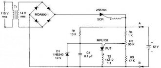
Rice. 1 - Circuit of a simple DC/DC converter No. 1
This diagram shows a relaxation self-oscillator, which is a blocking oscillator with counter-connection of the transformer windings. The principle of operation of this converter is as follows: when turned on, the current flowing through one of the windings of the transformer and the emitter junction of the transistor opens it, as a result of which it opens and more current begins to flow through the second winding of the transformer and the open transistor. As a result, an EMF is induced in the winding connected to the base of the transistor, which turns off the transistor and the current through it is interrupted. At this moment, the energy stored in the magnetic field of the transformer, as a result of the phenomenon of self-induction, is released and a current begins to flow through the LED, causing it to glow. Then the process is repeated.
The components from which this simple step-up voltage converter can be assembled can be completely different. A circuit assembled without errors is highly likely to work correctly. We even tried using the MP37B transistor - the converter functions perfectly! The most difficult thing is to make a transformer - it must be wound with a double wire on a ferrite ring, while the number of turns does not play a special role and ranges from 15 to 30. Less does not always work, more does not make sense. Ferrite - any, it doesn’t make much sense to take the N87 from Epcos, just as it doesn’t make sense to look for the domestically produced M6000NN. The currents flowing in the circuit are negligible, so the size of the ring can be very small; an outer diameter of 10 mm will be more than enough. A resistor with a resistance of about 1 kilo ohm (no difference was found between resistors with a nominal value of 750 ohms and 1.5 kohms). It is advisable to choose a transistor with a minimum saturation voltage; the lower it is, the more discharged the battery can be used. The following were tested experimentally: MP 37B, BC337, 2N3904, MPSH10. LED - any available one, with the caveat that a powerful multi-chip one will not glow at full strength.
The assembled device looks like this:
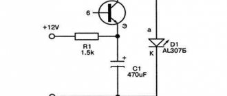
Rice. 3 - Converter assembled according to scheme No. 1
The board size is 15 x 30 mm, and can be reduced to less than 1 square centimeter using SMD components and a small enough transformer. Without a load, this circuit does not work.
The second circuit is a typical step-up converter made with two transistors. The advantage of this circuit is that during its manufacture there is no need to wind the transformer, but just take a ready-made inductor, but it contains more parts than the previous one.
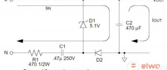
Fig. 7 - Diagram of a simple DC/DC converter No. 2
The operating principle boils down to the fact that the current through the inductor is periodically interrupted by transistor VT2, and the self-induction energy is directed through the diode to capacitor C1 and transferred to the load. Again, the circuit is workable with completely different components and element values. Transistor VT1 can be BC556 or BC327, and VT2 BC546 or BC337, diode VD1 can be any Schottky diode, for example, 1N5818. Capacitor C1 - any type, with a capacity from 1 to 33 μF, no longer makes sense, especially since you can do without it altogether. Resistors - with a power of 0.125 or 0.25 W (although you can also supply powerful wire-wound ones, about 10 watts, but this is more wasteful than necessary) of the following ratings: R1 - 750 Ohm, R2 - 220 KOhm, R3 - 100 KOhm. At the same time, all resistor values can be completely freely replaced with those available within 10-15% of those indicated; this does not affect the performance of a correctly assembled circuit, but it does affect the minimum voltage at which our converter can operate.
The most important part is inductor L1, its rating can also differ from 100 to 470 μH (values up to 1 mH have been experimentally tested - the circuit works stably), and the current for which it should be designed does not exceed 100 mA. Any LED, again taking into account that the output power of the circuit is very small. A correctly assembled device starts working immediately and does not require configuration.
The output voltage can be stabilized by installing a zener diode of the required value in parallel with capacitor C1, however, it should be remembered that when connecting a consumer, the voltage may sags and become insufficient. ATTENTION! Without load, this circuit can produce voltages of tens or even hundreds of volts! If used without a stabilizing element at the output, capacitor C1 will be charged to the maximum voltage, which, if the load is subsequently connected, can lead to its failure!
The converter is also made on a 30 x 15 mm board, which allows it to be attached to an AA size battery compartment. The PCB layout looks like this:
Both simple circuits of boost converters can be made with your own hands and can be successfully used in camping conditions, for example in a lantern or lamp for lighting a tent, as well as in various electronic homemade products for which the use of a minimum number of batteries is critical.
Chapter 5 — Assembling the layout and testing the converter
Let's proceed to the most interesting and colorful stage, namely, assembling the layout and checking its functionality. At the beginning of the article, I mentioned the relationship between buck and boost topologies, let's look at this now, because on the half-bridge module this is extremely clear. First of all, let's look at the buck converter circuit:
The green frame highlights the components that are installed on the half-bridge power module, as you can see here C1 acts as an input capacitance, and capacitor C2 acts as an output capacitor. Now let's depict the boost converter circuit:
Who is attentive and noticed what has changed? Yes, in principle, nothing has changed, oddly enough, the only difference is that the entrance and exit have changed places. As you can see, the topologies themselves are identical, and this leads to another interesting property - if a synchronous topology is used, then the converter can work as a bidirectional converter!
Example? Easily! Let's imagine a portable device with USB and Li-ion battery. When the USB is connected, the converter operates in buck mode and charges the battery; as soon as the USB cable is disconnected, the converter switches to boost mode and raises from 4.2V to 5V from which the device is powered. Cool! And there are quite a lot of similar tasks where this feature is useful.
I assembled the prototype according to the second circuit, and in it the capacitor C1 is exactly the output capacitance, that is, it is already installed and it is enough to put the inductor that we made and the input capacitance on the module. I used a pair of 4700 µF 25V electrolytic capacitors as input capacitance C2 and ended up with this layout of the power section:
Now we connect the control module and power source to the power part, in this case a laboratory power supply:
Now let’s upload the firmware to the microcontroller, supply power from the laboratory, set the duty cycle to 30,000 out of 45,000, which, according to our formula, will increase the input voltage by 3 times: Vout = 12V / (1 - 0.66) = 12/0.33 = 36.36V . After this we will see that the lamp lights up brightly:
Now we connect the oscilloscope to the same points and see the following result:
As you can see, the device works correctly: the voltage has actually increased 3 times, the input consumption is about 60 W ( yes, I know that the lamp needs 36V “changes”
), the lamp itself consumes a current of 1.61 A. For clarity, I’ll leave a short video in progress:
It remains to find out how much the converter heats up under these conditions.
I assumed that overheating would be minimal, because... everything was calculated correctly, and the components were taken with reserve, so I placed the converter in an environment with a temperature of approximately +10 oC to enhance the contrast of the temperature field. My testing method is simple and consists of three stages:
- I place the converter in an environment with a temperature of +10 oC and wait until it cools down and becomes practically indistinguishable in the thermal imager against the general background;
- I turn on the converter, let it run for 5 minutes and measure the general appearance of the converter and separately the power components;
- I leave the converter running for another 1 hour and measure again to see how much the component temperatures have increased.
After this experiment, it will be possible to draw approximate conclusions about the possibility of operating the converter in long-term modes, as well as understand how much the device overheats relative to the ambient temperature, which will make it possible to predict the behavior of the device at higher ambient temperatures. And so let's get started:
- Measurement No. 1 - the converter was placed in an environment with a temperature of about +10 oC:
Here you can see that the boards have almost completely merged with the environment, which means you can turn on and begin assessing the temperatures of the converter already under rated load.
- Measurement No. 2 - the converter operates at 100% rated load for 5 minutes, ambient temperature is about +10 oC:
After 5 minutes of operation, the picture became more contrasting and both the converter itself and the main heating components were clearly visible. The record holders for overheating are insulated dc/dc for transistor drivers with a temperature of +29 oC, but there is nothing strange here, because the overheating temperature of +20…30 oС is nominal for them, which is reflected in the documentation. The second place is occupied by the throttle, the temperature of which is +28...29 oС, which is more than good, because Often the operating chokes may well reach the bar at +80...100 oC. The radiator temperature is +20...21 oC, and the transistors are only a degree hotter, or maybe less, because Any thermal imager is actually not the most accurate device in the world.
- Measurement No. 3 - the converter operates at 100% rated load for 1 hour, ambient temperature is about +10 oC:
After an hour of operation, the temperatures increased and settled down, I tried to measure again after 3 hours, but the result did not change, or rather the changes were at the level of measurement error, so I did not add this stage. For now, let's look at the temperatures after the converter reaches cruising speed in the nominal mode.
The temperature of the radiator increased by +4 oC, and the transistors “merged” with it, because everything warmed up and the heat flow was evenly distributed. The temperature on the isolated dc/dc increased by +9 oC and they reached the overheating ratings, even the margin remained a couple of degrees. The throttle temperature increased by +3 oC.
Let's summarize... The temperature of the transistors is normal, which means the losses are negligible and the power module itself works correctly, there are no through currents, there are no problems with installing the transistors, by the way, they sit on a ceramic substrate in a drop of MX-4 thermal paste, you don’t need to add a lot of paste - will be worse.
The temperature of the inductor is also normal, which means the inductance was calculated correctly and the core dimensions were also suitable, yes, with a 5-fold margin :)), that is, it does not become saturated and the winding does not overheat with the current value of the current density.
Bonus for the curious
Keep a light bulb in your thermal imager :))
Using the transceiver
You can assemble a step-down voltage converter with your own hands using a step-down voltage transformer. In this case, three amplifiers will be needed. One of them is installed directly behind the inductor. The other two are located behind the transformer. For successful operation of the device, one filter will be enough. The transceiver is connected to the converter via a choke.
To increase current conductivity, you can use a zener diode. A frequency regulator must be installed if the coil is available at 50 A. In other cases there is no need to share the load. The filter will ensure safe operation of the device.
Transformer with open rectifier
It is very easy to assemble such a converter with your own hands. First you need to install the coil with the primary winding. Choose those that can withstand voltages greater than 30 Ohms. The rectifier itself is mounted adjacent to the tetrode.
It is better to choose open resistors. An amplifier cannot be installed in this circuit. If you are building a 60A device, they should be soldered next to the coil. When everything is ready, the terminal blocks are secured.