The article will discuss the choice of a power supply unit (which is connected to a 230V or 400V AC network). The power supply is understood as both a separate device (adapter) and part of the device. A transformer power supply is a power supply based on a low-frequency transformer. By pulse we mean a power supply with a circuit for generating high-frequency pulses and a high-frequency transformer (a choke in the case of a flyback).
So you are designing a device or you already have one and need to be powered from the network, i.e. need a power supply. Which power supply to choose: transformer or pulse? There cannot be a definite answer here; each type of power supply has its own advantages, disadvantages and features, and we will talk about them in this article.
We will compare and select a power supply according to the following main criteria:
— decoupling from the network; — pulsations and interference; — output voltage stability.
Types of power supplies
Today, switching voltage sources are widely used. Compared to traditional transformer circuits, they have a significant advantage in energy efficiency and weight and size indicators. It is believed that at load currents of more than 5 amperes they have undeniable preferences. But they also have disadvantages - for example, the generation of RF interference into the supply network and into the load. And the main obstacle to home assembly is the complexity of the circuits and the need for special skills to make winding parts. Therefore, it is better for a semi-skilled home craftsman to start making a power supply according to the usual principle with a network step-down transformer.
Ripple and Interference
The concepts of ripple and interference are quite close and can have different interpretations. In this article, ripple refers to voltage/current fluctuations caused by natural processes. Interference refers to voltage/current fluctuations (surges) caused by various “parasitic” phenomena. For example: voltage fluctuations at the output of the power supply after the rectifier and LC filter - ripple. Voltage surges caused by switching switches are interference. Another example: voltage fluctuations at the output of a transformer power supply after a rectifier and filter with a frequency of 100 Hz - ripples induced by the stray field - voltage fluctuations in the circuit - interference. Roughly speaking, interference is an unnatural (interfering) voltage fluctuation. This classification may not be entirely scientific and correct, but it allows us to simplify the presentation of the material.
First, let's deal with pulsations. In the case of a transformer power supply, the output voltage ripple is usually higher than that of a switching (stabilized) power supply. This is due to the low frequency of voltage pulses at the output of the transformer power supply rectifier. However, the low-frequency ripple of the transformer power supply is effectively suppressed by analog circuits (op-amps, linear stabilizers, etc.). The ripple frequency of a switching power supply is tens and even hundreds of kilohertz. The degree of suppression of such high-frequency ripples in the power supply of analog circuits is much less and they can “penetrate” their output. For example, in the circuit of the input path of an ADC on an operational amplifier, power supply ripples can overlap the useful signal. To suppress high-frequency ripple in the power supply circuits of operational amplifiers, RC filters are often used: a resistor with a resistance of 10-100 Ohms and a ceramic capacitor with a capacity of 0.1-10 μF. If it is necessary to reduce the ripple of a switching power supply in the power circuit, then additional LC filters are used.
With interference the situation is much worse. If the magnitude of ripples can be more or less analyzed at the design stage, then it is difficult to assess the magnitude of interference.
In the case of a transformer power supply, interference is created by the leakage field of the transformer; for toroidal transformers it is less, and for W-shaped transformers it is larger. Analog circuits that process low-level signals (precision multimeters, audio amplifiers, radio equipment) especially suffer from this interference. To suppress interference from a low-frequency transformer, shielding shells (casings) made of steel or tin are used.
In switching power supplies, the main noise is created when switching transistors and restoring diodes. Suppressing these interferences is a very broad and rather boring topic. It will be much more useful to consider the topologies (types) of switching power supplies in terms of noise generation.
Flyback switching power supplies are the worst choice in terms of interference. These switching power supplies, among others, are most susceptible to powerful pulse noise. The design and selection of such power supplies must be approached more carefully, especially if its power is tens of watts.
Half-bridge and full-bridge switching power supplies are the best choice from the point of view of interference. Power supplies of this topology usually have lower noise levels. A special case of half-bridge and bridge switching power supplies are resonant circuits in which transistors are switched at zero voltage or current, due to which the resulting interference is minimal.
Other topologies of switching power supplies occupy an intermediate position between flyback and half-bridge (bridge) circuits. This classification should not be taken literally; the amount of interference strongly depends on the implementation, and if poorly executed, the resonant circuit can “noise” more than a well-designed and manufactured flyback.
Bottom line . When choosing a power supply, it should be taken into account that the interference from switching power supplies is greater than from transformer ones, but the interference from switching power supplies is of a higher frequency (usually tens of megahertz) and short duration. If interference from a transformer unit can be heard in the literal sense, then interference from switching power supplies can only be seen with an oscilloscope. This does not mean that interference from switching power supplies can be ignored; its strong level can disrupt the operation of digital circuits and create interference on the radio. But it must be borne in mind that in many cases the insignificant level of interference from a well-designed switching power supply does not have a significant effect on the operation of the device (and neighboring devices).
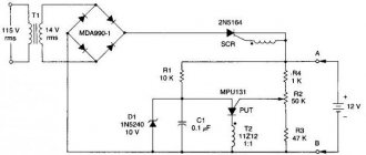
Transformer power supply circuit
Schematic diagram of the power supply.
The circuit of a 12 volt power supply operating from a 220 V network consists of the following components:
- A step-down transformer . It consists of iron, primary and secondary (there may be several) windings. Without going deeply into the principle of operation, it should be noted that the output voltage depends on the ratio of the turns of the primary (n1) and secondary (n2) windings. To obtain 12 volts, the secondary winding must contain 220/12 = 18.3 times fewer turns than the primary.
- Rectifier. Most often it is performed in the form of a full-wave circuit (diode bridge). Converts alternating voltage into pulsating voltage. The current passes through the load twice in one direction per period.
Operation of a full-wave rectifier. - Filter .
Converts pulsating voltage into constant voltage. It charges when voltage is applied and discharges during pauses. It consists of a high-capacity oxide capacitor, in parallel with which a ceramic capacitor with a capacity of about 1 μF is often connected. To understand the need for this additional element, we must remember that the oxide capacitor is designed in the form of strips of foil rolled into a roll. This roll has parasitic inductance, which significantly degrades the quality of filtering high-frequency interference. To do this, an additional HF pulse short-circuit capacitor is turned on. Equivalent filter circuit with oxide and additional capacitors. - Stabilizer . May be missing. Schemes of simple but effective units are discussed below.
The following sections discuss the procedure for selecting and calculating each element of a 12-volt DC voltage source.
How does the power supply that works in each system unit work?
The power supply has been removed from the case.
The bundle of wires on the left connects to the computer. The big component in the middle of the transformer type is the filter inductor. Clickable, like all the photos in the article Have you ever wondered what is inside the power supply unit (PSU) of your computer? The task of the PSU is to convert power from the mains (120 or 240 V alternating current, AC) into a stable supply of direct current, that is, unidirectional current (DC), which your computer needs. The power supply must be compact and cheap, while converting current efficiently and safely. For these purposes, various manufacturing methods are used, and the power supply units themselves are much more complicated inside than you think.
In this article we will analyze the ATX standard unit and explain how it works1. Like most modern power supplies, ours uses a design known as a “switching mode power supply” (UPS). Now they are very cheap, but this was not always the case. In the 1950s, complex and expensive UPS systems were used only in rockets and space satellites with critical size and weight requirements. However, by the early 1970s, new high-voltage transistors and other technological improvements made UPSs much cheaper, so that they became widely used in computers. Today you can buy a phone charger with a UPS inside for a few dollars.
Our ATX UPS is packaged in a metal case the size of a brick, from which comes a multitude of multi-colored cables. Inside the case we see tightly packed components. The design engineers were clearly concerned about the compactness of the device. Many components are covered with radiators. They cool power semiconductors. The built-in fan does the same for the entire power supply. On the KDPV it is on the right.
Let's start with a brief overview of how a UPS works and then describe the components in detail. A kind of “conveyor” in the photograph is organized from right to left. On the right, the UPS receives AC power. The input AC current is converted to high voltage DC using several large filter components. This direct current switches on and off thousands of times per second to generate pulses that are fed into a transformer. It converts high-voltage pulses into high-current low-voltage ones. These pulses are converted to DC and filtered to provide good, clean power. It is supplied to the motherboard, drives and drives through the cables in the photo on the left.
While the process may seem overly complicated, most consumer electronics from cell phones to TVs are actually powered by a UPS. High-frequency current allows you to make a small, lightweight transformer. In addition, pulse power supplies are very effective. The pulses are adjusted to provide only the power needed, rather than turning excess power into waste heat, as in a linear power supply.
The first step is for the input AC current to pass through an input filter circuit, which filters out electrical noise, which is random changes in electrical current that degrade signal quality.
The filter below consists of inductors (toroidal coils) and capacitors. Square gray capacitors are special Class X components for safe connection to AC power lines.
Input Filter Components
Alternating current with a frequency of 60 hertz in the network changes direction 60 times per second (AC), but the computer needs direct current in one direction (DC). The full bridge rectifier in the photo below converts alternating current to direct current. The DC outputs on the rectifier are marked with ? and +, and alternating current enters through two central contacts, which constantly change their polarity. There are four diodes inside the rectifier. The diode allows current to flow in one direction and blocks it in the other direction, so the result is that alternating current is converted to direct current flowing in the desired direction.
The marking GBU606 is visible on the bridge rectifier. The filter circuit is located to the left of the rectifier. The large black capacitor on the right is one of the voltage doublers. The little yellow capacitor is a special ceramic Y-capacitor that protects against voltage surges
Below are two diagrams of how a bridge rectifier works. In the first diagram, the top AC input has positive polarity. The diodes pass current to the DC output. In the second diagram, the AC inputs have changed polarity, as happens all the time in AC. However, the diode configuration ensures that the output current remains unchanged (the plus is always on top). Capacitors smooth the output.
The two diagrams show the current flow as the AC input signal fluctuates. Four diodes cause current to flow in the direction of the arrow
Modern power supplies accept a “universal” input voltage from 85 to 264 volts AC, so they can be used in different countries regardless of the local network voltage. However, the circuitry of this old PSU could not cope with such a wide range. Therefore, a switch is provided to select 115 or 230 V.
Switch 115/230V
The switch uses a clever voltage doubler circuit. The idea is that with the switch closed (at 115V), the AC input bypasses the two bottom diodes in the bridge rectifier and instead connects directly to the two capacitors. When the top AC input is positive, the top capacitor receives full voltage. And when the “plus” is below, then the bottom. Since the DC output comes from both capacitors, the output always produces double the voltage. The fact is that the rest of the power supply receives the same voltage regardless of whether the input is 115 or 230 V, which simplifies its design. The disadvantage of a doubler is that the user must set the switch to the correct position, otherwise they risk damaging the power supply, and the power supply itself requires two large capacitors. Therefore, in modern power supplies, the voltage doubler has gone out of fashion.
Voltage doubler circuit. Each capacitor receives full voltage, so the DC output is double voltage. Gray diodes are not used in doubler operation
For safety reasons, high voltage and low voltage components are separated mechanically and electrically, see photo below.
The main side contains all the circuits that connect to the AC network. On the secondary side there are low voltage circuits. The two sides are separated by "border isolation", which is marked with a green dotted line in the photo. no
across the border . Transformers pass energy across this boundary through magnetic fields without a direct electrical connection. Feedback signals are transmitted to the main side using opto-isolators, that is, light pulses. This separation is a key factor in safe design: a direct electrical connection between the AC line and the PSU output creates a shock hazard.
Power supply with markings of main elements. Heatsinks, capacitors, control board and output cables have been removed for better visibility (SB stands for standby supply)
At this point, the input AC current has been converted to high-voltage DC current of about 320 V2. The direct current is cut into pulses by a switching transistor (switching transistor in the diagram above). This is a power MOSFET3. Since it gets hot during use, it is mounted on a large radiator. The pulses are fed into the main transformer, which in a sense is the heart of the power supply.
A transformer consists of several coils of wire wound around a magnetizable core. High-voltage pulses entering the primary winding of the transformer create a magnetic field. The core directs this magnetic field to other, secondary windings, creating voltage in them. This is how the UPS safely produces output current: there is no electrical connection between the two sides of the transformer, only a connection through a magnetic field. Another important aspect is that in the primary winding there are many turns of wire around the core, and in the secondary circuits there are much fewer. The result is a step-down transformer: the output voltage is much less than the input, but at a much higher voltage.
Switching transistor3 is controlled by an integrated circuit called “UC3842B PWM Current Mode Controller”. This chip can be considered the brain of the power supply. It generates pulses at a high frequency of 250 kilohertz. The width of each pulse is adjusted to provide the required output voltage: if the voltage starts to drop, the chip produces wider pulses to pass more energy through the transformer4.
Now you can look at the second, low-voltage part of the power supply. The secondary circuit produces four output voltages: 5, 12, ?12 and 3.3 volts. For each output voltage there is a separate transformer winding and a separate circuit for obtaining this current. Power diodes (below) convert the transformer outputs to DC current. Inductors and capacitors then filter the output from voltage spikes. The power supply must regulate the output voltage to maintain it at the proper level even when the load increases or decreases. Interestingly, BP uses several different control methods.
Close-up view of the output diodes. On the left are cylindrical diodes mounted vertically. In the center are pairs of rectangular Schottky power diodes, with two diodes in each housing. These diodes are attached to a heatsink for cooling. On the right, notice the two copper wires in the shape of staples. They are used as resistors to measure current
The main outputs are 5 and 12 V. They are regulated by a single controller chip on the main side. If the voltage is too low, the IC increases the pulse width, passing more power through the transformer and increasing the voltage on the secondary side of the power supply. And if the voltage is too high, the chip reduces the pulse width. Note: The same feedback circuit drives the 5V and 12V outputs, so a load on one output may change the voltage on the other. In higher quality power supplies, the two outputs are regulated separately5.
Bottom side of the PCB. Pay attention to the large distance between the circuits of the main and secondary sides of the power supply unit. Also note how wide the metal tracks are on the main side of the power supply for high voltage current and how thin the tracks are for control circuits
You may be wondering how the controller IC on the primary side gets feedback about the voltage levels on the secondary side since there is no electrical connection between them (there is a wide gap visible in the photo). The trick is to use a clever chip called an opto-isolator. Inside the chip, on one side of the chip there is an infrared LED, on the other there is a light-sensitive phototransistor. The feedback signal is applied to the LED and detected by a phototransistor on the other side. In this way, the opto-isolator provides a bridge between the secondary and primary sides, transmitting information with light rather than electricity6.
The power supply also provides a negative output voltage (?12 V). This voltage is mostly obsolete, but was used to power serial ports and PCI slots. Regulation of the ?12V supply is fundamentally different from regulation of +5 and +12V. The ?12V output is controlled by a Zener diode (Zener diode), a special type of diode that blocks reverse current until a certain voltage level, and then begins to conduct it. Excess voltage is dissipated as heat through the power resistor (pink) under the control of the transistor and zener diode (since this approach wastes energy, modern high-efficiency power supplies do not use this method of regulation).
The ?12V supply is regulated by a tiny ZD6 zener diode, about 3.6mm long, on the underside of the PCB. The corresponding power resistor and transistor A1015 are located on the top side of the board
Perhaps the most interesting regulation circuit is the 3.3V output, which is regulated by a magnetic amplifier. A magnetic amplifier is an inductor with special magnetic properties that make it work like a key (switch). When current is applied to the inductor of a magnetic amplifier, it initially blocks the current almost completely as the inductor becomes magnetized and the magnetic field increases. When the inductor reaches full magnetization (that is, saturation), its behavior suddenly changes - and the inductor allows particles to flow unimpeded. The magnetic amplifier in the power supply receives pulses from the transformer. The inductor blocks the variable part of the pulse. The 3.3V output is adjusted by changing the pulse width7.
The magnetic amplifier is a ring made of ferrite material with special magnetic properties. Several turns of wire are wound around the ring
The power supply contains a small board on which the control circuit is located. This board compares the voltage with a reference to generate feedback signals. It also monitors voltage to generate a “power good” signal. The circuit is installed on a separate perpendicular board, so it does not take up much space in the power supply.
The main components are mounted on the top side of the board with through-holes, and the bottom side is covered with tiny SMD components that are surface mount. Note the zero resistance resistors as jumpers
The power supply also has a second circuit - for backup power9. Even when the computer is formally "turned off", the five-volt backup power supply provides it with 10 W of power for functions that continue to operate: real-time clock, wake-on-LAN function, etc. The backup power circuit is almost an independent power supply: it uses a separate control chip, separate transformer and separate components on the secondary DC side, but the same components on the primary AC side. This system has a much lower power, so there is a smaller transformer in the circuit.
Black and yellow transformers: the backup transformer is on the left and the main transformer is on the right. A microcircuit is installed in front of it to control backup power. The large cylindrical capacitor on the right is the voltage doubler component. The white beads are silicone, which seals the components and holds them in place
An ATX power supply is complex internally, with many components ranging from massive inductors and capacitors to tiny surface-mount components10. However, this complexity makes it possible to produce efficient, small and safe power supplies. For comparison, I once wrote about a power supply from the 1940s that produced only 85 watts of power, but was the size of a suitcase, weighed 50 kg and cost a fortune. Nowadays, with advanced semiconductors, they make much more powerful power supplies for less than $50, and such a device will fit in your hand.
REC-30 power supply for a 1940s Model 19 (US Navy) teletype
I've written about power supplies before, including a history of power supplies in IEEE Spectrum. You might also like our detailed breakdowns of the Macbook charger and iPhone charger.
1 Intel introduced the ATX standard for personal computers in 1995. The ATX standard (with some updates) still defines the motherboard, case, and power supply configuration of most desktop computers. Here we are studying a power supply from 2005, and modern power supplies are more advanced and efficient. The basic principles are the same, but there are some changes. For example, instead of magnetic amplifiers, DC/DC converters are used almost everywhere.
Label on the power supply
The PSU label indicates that it was manufactured by Bestec for the Hewlett-Packard Dx5150 desktop computer. This power supply slightly does not correspond to the ATX format; it is more elongated in length. [return]
2 You may wonder why 230V AC is converted to 320V DC. The reason is that AC voltage is usually measured as RMS voltage, which in a sense averages out the changing waveform. In fact, a 230-volt AC signal has peaks up to 320 volts. The PSU capacitors are charged through the diodes to peak voltage, so the DC current is approximately 320 volts (although it sags a bit during the cycle). [return]
3 The power transistor is a FQA9N90C power MOSFET. It can handle 9 amps and 900 volts. [return]
4 The integrated circuit is powered by a separate winding on a transformer, which provides 34 volts to operate it. There is a chicken and egg problem: the control chip creates pulses for the transformer, but the transformer powers the control chip. The solution is a special trigger circuit with a 100 kΩ resistor between the microcircuit and the high voltage current. It provides a small current to start the chip. As soon as the chip starts sending pulses to the transformer, it is powered by it. [return]
5 The method of using one control loop for two outputs is called cross control. If the load on one output is much higher than the other, the voltages may deviate from their values. Therefore, many power supplies have minimum load requirements on each output. More advanced power supplies use DC/DC converters for all outputs to control voltage accuracy. For more information on cross-regulation, see these two presentations. One of the methods discussed is multi-level arrangement of output windings, as in our power supply. Specifically, the 12-volt output is implemented as a 7-volt output on top of the 5-volt output, resulting in 12 volts. With this configuration, a 10% error (for example) in a 12-volt circuit would be only 0.7 V, not 1.2 V. [return]
6 The opto-isolators are PC817 components that provide 5000 volts of isolation between the sides of the PSU (that is, between the high and low sides). Note the slot in the PCB under the opto-isolators. This is an additional safety measure: it ensures that high voltage current does not pass between the two sides of the opto-isolator along the surface of the printed circuit board, for example, in the presence of contamination or condensation (in particular, the slot increases the creepage distance). [return]
7 The pulse width through the magnetic amplifier is set by a simple control circuit. In the reverse part of each pulse, the inductor is partially demagnetized. The control circuit regulates the demagnetization voltage. Higher voltage increases demagnetization. The inductor then takes longer to remagnetize and thus blocks the input pulse longer. With a shorter pulse in the circuit, the output voltage decreases. Conversely, a lower demagnetization voltage results in less demagnetization, so the input pulse is not blocked for as long. As a result, the output voltage is regulated by changing the demagnetization voltage. Please note that the pulse width in the magnetic amplifier is controlled by the control chip. The magnetic amplifier reduces these pulses as needed while regulating the 3.3V output voltage. [return]
8 The control board contains several chips, including an LM358NA op-amp, a TPS3510P supervisor/reset chip, an LM339N four-channel differential comparator, and an AZ431 precision reference. The supervisor chip is interesting - it is specifically designed for the PSU and controls the output voltage so that it is not too high and not too low. The AZ431 precision reference is a variant of the TL431 reference chip that is often used in PSUs to provide a reference voltage. I already wrote about the TL431. [return]
9 The backup power supply uses a different configuration - a flyback transformer. A control chip A6151 with a switching transistor is installed here, which simplifies the design.
Power supply circuit using A6151. It is taken from the reference book, therefore it is not identical to the diagram of our power supply, although it is close to it
[return]
10 If you want to study detailed diagrams of various ATX format power supplies, I recommend Dan Melnik’s site. It’s surprising how many power supply implementations there are: different topologies (half-bridge or direct), the presence or absence of power factor conversion (PFC), a variety of control, regulation and monitoring systems. Our power supply is quite similar to the direct topology power supply without PFC, at the bottom of that page on Dan's site. [return]
Transformer selection
There are two ways to obtain a suitable transformer. Independent production of a step-down block and selection of a suitable one in the factory. In any case, you need to keep in mind:
- at the output of the step-down winding of the transformer, when measuring the voltage, the voltmeter will show the effective voltage (1.4 times less than the amplitude);
- on the filter capacitor without load, the constant voltage will be approximately equal to the amplitude voltage (they say that the voltage on the capacitor “rises” by 1.4 times);
- if there is no stabilizer, then under load the voltage on the capacitor will drop depending on the current;
- For the stabilizer to operate, a certain excess of the input voltage over the output voltage is required; their ratio limits the efficiency of the power supply as a whole.
From the last two points it follows that for normal operation of the power supply, the transformer voltage must exceed 12 V.
Decoupling from the network
It is assumed that the selected power supply provides galvanic isolation from the network. Which of the two types of power supplies will provide maximum isolation? At first glance, the choice is obvious - a transformer power supply, since a switching power supply contains a Y capacitor (or even several) between the input and output.
In theory, a transformer power supply does provide complete isolation from the network, but in practice this is not always the case, especially for toroidal transformers.
In the manufacture of toroidal transformers, the secondary winding is wound on top of the primary and a parasitic capacitor is formed between them. In this case, an alternating mains voltage is applied to the parasitic capacitor. Unfortunately, manufacturers do not standardize the value of the interwinding capacitance of transformers in any way, and it can only be found out by actual measurement “on site”. The general trend is that the higher the power (size) of the transformer, the higher the interwinding capacitance. In addition to the size of the transformer, the value of the interwinding capacitance is affected by the quality of the insulation.
For example, the photo below shows the results of measuring the interwinding capacitance of various toroidal transformers. Capacitance was measured with an RLC meter E7-22 at a frequency of 120 Hz.
In W-shaped transformers, usually the primary and secondary windings are divided into separate sections, so the value of the interwinding capacitance is much less.
Let's return to switching power supplies. The typical value of the capacitance Y of the capacitor between the input and output is 2.2 nF. You can often find a higher value up to 4.7 nF, less often a lower value of 1 nF. Thus, a power supply on a powerful toroidal transformer between the input and output can have a capacity comparable or even greater than in a high-quality switching power supply. At the same time, the presence of capacitance in a switching power supply is known, but this feature of a toroidal transformer is usually not indicated anywhere.
Why is this very container “harmful”? First of all, the parasitic potential at the output relative to ground. This potential can be tens of volts, and if you touch the output of the power supply (or the device powered by it) with a grounded soldering iron or simply with your hand, it will cause the device to fail.
In switching power supplies, to reduce the output potential relative to ground and further reduce interference, capacitors are installed between the output and ground. The recommended total capacitance of capacitors is no more than 20 nF.
Since the specified capacitors are not installed in all switching power supplies, and the value of the interwinding capacitance for toroidal transformers is not standardized, when using them it is recommended to check for the presence of parasitic potential at the output. To do this, you can use a multimeter in AC voltage measurement mode and, with the power supply turned on, take one probe in your hand (or connect it to ground) and connect the second one to the output of the power supply.
Another negative impact of interwinding capacitance is the penetration of network noise. In this case, switching power supplies are in a more advantageous position because In most cases, they have an input filter installed. This filter prevents interference from entering the network from a switching power supply and vice versa.
Bottom line . When choosing a power supply, if you require maximum isolation from the network, then it is better to use a transformer power supply with a III core and separated windings. It should be taken into account that the W transformer has a larger stray field and can induce interference of 50 Hz. In some particularly sensitive devices, two toroidal transformers are installed in series, which ensures high isolation and low interference of 50 Hz.
Self-winding transformer
The complete calculation and manufacture of a homemade power transformer is complex, time-consuming, and requires tools and skills. Therefore, a simplified path will be considered - selecting a block suitable for hardware and converting it to 12 V.
If there is a ready-made transformer, but there is no wiring diagram for it, you need to call its windings with a tester. The winding with the highest resistance will most likely be the mains winding. The remaining windings must be removed.
Next, you need to measure the thickness of the iron set b and the width of the central plate a and multiply them. The cross-sectional area of the core will be S=a*b (in sq.cm). It determines the power of the transformer P=
. Next, the maximum current in amperes is calculated, which can be removed from a winding with a voltage of 12 volts: I = P/12.
Determination of core area.
Next, the number of turns per volt is calculated using the formula n=50/S. For 12 volts, you need to wind 12*n turns with a margin of about 20% for losses in copper and on the stabilizer. And if it is not there, then the voltage drop under load. And the last step is to select the cross-section of the winding wire according to the schedule for a current density of 2-3 mA/sq.mm.
Selecting copper wire.
For example, there is a transformer with a 220 V primary winding with a set of iron 3.5 cm thick and a middle tongue width of 2.5 cm. This means S = 2.5 * 3.5 = 8.75 and the power of the transformer
=3 W (approx.) Then the maximum possible current at 12 volts is I=P/U=3/12=0.25 A. For winding, you can choose a wire with a diameter of 0.35..0.4 sq. mm. For 1 volt there are 50/8.75 = 5.7 turns, you need to wind 12 * 5.7 = 33 turns. Taking into account the reserve - about 40 turns.
Main components of a regulated power supply
The transformer power supply in most cases is made according to the following block diagram.
Transformer power supply units.
A step-down transformer reduces the network voltage to the required level. The resulting alternating voltage is converted into pulsed voltage using a rectifier. The choice of its circuit depends on the circuit of the secondary windings of the transformer. The most commonly used full-wave bridge circuit is used. Less often - half-wave, since it does not allow the transformer’s power to be fully used, and the ripple level is higher. If the secondary winding has a center point brought out, then the full-wave circuit can be built with two diodes instead of four.
Full-wave rectifier for midpoint transformer.
If the transformer is three-phase (and there is a three-phase circuit to power the primary winding), then the rectifier can be assembled using a three-phase circuit. In this case, the ripple level is the lowest, and the power of the transformer is used most fully.
After the rectifier, a filter is installed that smoothes the pulse voltage to constant. Typically, the filter consists of an oxide capacitor, parallel to which a low-capacity ceramic capacitor is placed. Its purpose is to compensate for the structural inductance of the oxide capacitor, which is made in the form of a rolled strip of foil. As a result, the resulting parasitic inductance of such a coil worsens the filtering properties at high frequencies.
Next is the stabilizer. It can be either linear or pulsed. The pulse type is more complicated and negates all the advantages of a transformer power supply in the output current niche of up to 2..3 amperes. If you need an output current higher than this value, it is easier to switch the entire power supply, so a linear regulator is usually used here.
The output filter is based on an oxide capacitor with a relatively small capacitance.
Generalized block diagram of a pulse power supply.
Switching power supplies are built on a different principle. Since the current consumed is sharply non-sinusoidal, a filter is installed at the input. It does not affect the performance of the unit in any way, which is why many industrial manufacturers of Economy class power supplies do not install it. You don’t have to install it in a simple homemade source, but this will lead to the fact that devices on microcontrollers powered by the same 220 volt network will begin to fail or work unpredictably.
Then the mains voltage is straightened and smoothed out. An inverter using transistor switches in the primary winding circuit of the transformer creates pulses with an amplitude of 220 volts and a high frequency - up to several tens of kilohertz, in contrast to 50 hertz in the network. Due to this, the power transformer is compact and lightweight. The secondary winding voltage is rectified and filtered. Due to the high conversion frequency, smaller capacitors can be used here, which has a positive effect on the dimensions of the device. Also, in high-frequency voltage filters, it becomes advisable to use chokes - small-sized inductors effectively smooth out HF pulsations.
Voltage regulation and current limitation are performed through feedback circuits, which are supplied with voltage from the source output. If, due to an increase in load, the voltage begins to decrease, then the control circuit increases the interval of the open state of the keys without reducing the frequency (pulse width control method). If the voltage needs to be reduced (including to limit the output current), the time the switches are open is reduced.
Selection of a finished transformer
If you have a ready-made transformer with a secondary winding suitable for current and voltage, you can try to select a ready-made one. For example, in the TPP series there are suitable products with a voltage of secondary windings close to 12 volts.
| Transformer | Designation of secondary winding terminals | Voltage, V | Allowable current, A |
| Chamber of Commerce and Industry48 | 11-12, 13-14, 15-16, 17-18 | 13,8 | 0,27 |
| TPP209 | 11-12, 13-15 | 11,5 | 0,0236 |
| TPP216 | 11-12, 13-14, 15-16, 17-18 | 11,5 | 0,072 |
The advantage of this solution is minimal labor intensity and reliability of factory execution. Minus - the transformer contains other windings, the overall power is also designed for their load. Therefore, in terms of weight and size, such a transformer will lose.
How to stabilize an electronic transformer
Stabilization occurs using filters in the form of filter capacitors. You can also use conventional wire stabilizers designed for high-frequency electronic transformers. They are connected through secondary winding triggers. A high frequency electronic transformer can be connected. The connection diagram assumes the use of triggers with a secondary winding. Electronic load lamps are installed on the relay, and the negative resistance is increased by filters.
Bipolar power supply without amplifier
Making a power supply from a simple electronic transformer is not so simple, since you need to determine all its characteristics, which should be based on when choosing capacitors, filters and diodes. But, if you strictly follow the scheme, something will work out.
Selecting diodes and making a rectifier
Diodes in the rectifier are selected according to three parameters:
- highest permissible forward voltage;
- highest reverse voltage;
- highest operating current.
According to the first two parameters, 90 percent of available semiconductor devices are suitable for operation in a 12-volt circuit; the choice is mainly made based on the maximum long-term permissible current. The design of the diode body and the method of manufacturing the rectifier also depend on this parameter.
If the load current does not exceed 1 A, you can use foreign and domestic one-ampere diodes:
- 1N4001-1N4007;
- HER101-HER108;
- KD258 (“droplet”);
- KD212 and others.
KD105 (KD106) devices are designed for lower currents (up to 0.3 A). All of the listed diodes can be mounted either vertically or horizontally on a printed circuit board or circuit board, or simply on pins. They don't need radiators.
Diode bridge made of low-power elements.
If large operating currents are needed, then other diodes must be used (KD213, KD202, KD203, etc.). These devices are designed for operation on heat sinks; without them they will withstand no more than 10% of the maximum rated current. Therefore, you need to select ready-made heat sinks or make them yourself from copper or aluminum.
Another diode bridge design.
It is also convenient to use ready-made bridge diode assemblies KTs405, KVRS or similar. There is no need to assemble them - just apply an alternating voltage to the corresponding terminals and remove the constant one.
Assembly of KVRS3510.
How to convert a transformer into a power supply or charger with your own hands
You cannot use a regular transformer as a power supply, since its output produces high-frequency alternating voltage. In addition, most of these devices cannot function without minimal loads, and they need improvement. Below is how to make a charger from an electronic transformer with your own hands. At the same time, it does not need to be disassembled, just connect a small board to it.
You may be interested in Features of magnetic tape for an electric meter
The board is based on a Schottky diode, as well as a filter capacitor. Also, to start the power supply, you must connect a light bulb to its output. The diode is selected based on the available parameters of the output voltage and maximum current.
Important! The maximum reverse voltage of the diode should be several times higher than the output voltage of the electrical transformer.
This circuit works great and produces a constant and smooth current. If desired, you can install a more expensive filter device and several capacitors. If you regularly use such a power supply, you should install it on a radiator.
Transformer device modernization
Capacitor capacity
The capacitance of the capacitor depends on the load and the ripples it tolerates. To accurately calculate capacity, there are formulas and online calculators that can be found on the Internet. For practice, you can focus on the numbers:
- at low load currents (tens of milliamps), the capacitance should be 100..200 µF;
- at currents up to 500 mA, a capacitor of 470..560 μF is needed;
- up to 1 A – 1000..1500 µF.
For higher currents, the capacitance increases proportionally. The general approach is that the larger the capacitor, the better. Its capacity can be increased to any limit, limited only by size and cost. In terms of voltage, you need to take a capacitor with a serious margin. So, for a 12-volt rectifier it is better to take a 25-volt element than a 16-volt one.
These arguments are valid for unstabilized sources. For a power supply with a stabilizer, the capacity can be reduced significantly.
Strengths and weaknesses of pulsed sources
If we compare analog and pulse devices of the same power, the latter will have the following advantages:
- Small size and weight due to the absence of a low-frequency step-down transformer and control elements that require heat removal using large radiators. Thanks to the use of high-frequency signal conversion technology, it is possible to reduce the capacitance of the capacitors used in the filters, which allows the installation of smaller elements.
- Higher efficiency, since the main losses are caused only by transient processes, while in analog circuits a lot of energy is constantly lost during electromagnetic conversion. The result speaks for itself, increasing efficiency to 95-98%.
- Lower cost due to the use of less powerful semiconductor elements.
- Wider input voltage range. This type of equipment is not demanding in terms of frequency and amplitude; therefore, connection to networks of various standards is allowed.
- Availability of reliable protection against short circuits, overload and other emergency situations.
The disadvantages of pulse technology include:
The presence of RF interference is a consequence of the operation of the high-frequency converter. This factor requires the installation of a filter that suppresses interference. Unfortunately, its operation is not always effective, which imposes some restrictions on the use of devices of this type in high-precision equipment.
Special requirements for the load, it should not be reduced or increased. As soon as the current level exceeds the upper or lower threshold, the output voltage characteristics will begin to differ significantly from the standard ones. As a rule, manufacturers (even recently Chinese ones) provide for such situations and install appropriate protection in their products.
Output voltage stabilization
A stabilizer at the output of the power supply is not always needed. So, if you plan to use a power supply in conjunction with sound-reproducing equipment, then the output must have a stable voltage. And if the load is a heating element, the stabilizer is clearly unnecessary. To power an LED strip, you can do without the most complex power supply module, but on the other hand, a stable voltage ensures independence of the brightness of the glow during changes in the network and extends the life of the LED lamp.
If the decision to install a stabilizer has been made, then the easiest way is to assemble it on a specialized microcircuit LM7812 (KR142EN5A). The connection circuit is simple and does not require adjustment.
Stabilizer for 7812.
The input of such a stabilizer can be supplied with voltage from 15 to 35 volts. A capacitor C1 with a capacity of at least 0.33 μF must be installed at the input, and at least 0.1 μF at the output. The capacitor of the filter unit usually acts as C1 if the length of the connecting wires does not exceed 7 cm. If this length cannot be maintained, then the installation of a separate element will be required.
The 7812 chip has protection against overheating and short circuit. But it does not like reversing the polarity at the input and applying external voltage to the output - its life time in such situations is calculated in seconds.
Important! For load currents above 100 mA, installing an integrated stabilizer on the heat sink is mandatory!
Voltage selection
The required voltage is determined by the device the power supply will be used to power. You can use voltages of 12V, 3.3V, 5V and 9V. These are the most popular output voltage values, but it may have other values. It all depends on the design of the transformer, the number of windings and the cross-sectional size of the magnetic core used.
12V
A power supply with an output voltage of 12V has been widely used in everyday life since the end of the last century. They are used to power heating boilers, LED strips, gaming devices, welding machines, television set-top boxes and various household appliances.
3.3 V
Blocks with a voltage of this level are used primarily in personal computers, but can also be used to recharge other devices, for example, in welding machines.
5V
This type of transformer power supply is also used to provide power to computers and servers.
9V
This type of unit for powering devices is widely used for working with construction equipment and various household devices. For example, it powers a drill, grinder or hammer drill.
Increasing the output current of the stabilizer
The above circuit allows you to load the stabilizer with a current of up to 1.5 A. If this is not enough, you can power the unit with an additional transistor.
Circuit with an NPN structure transistor
External NPN transistor.
This circuit is recommended by the developers and is included in the datasheet for the chip. The output current should not exceed the maximum collector current of the transistor, which must be equipped with a heat sink.
Circuit with pnp transistor
If there is no semiconductor triode of the npn structure, then you can power the stabilizer with a semiconductor triode pnp.
External PNP transistor.
A silicon low-power VD diode increases the 7812's output voltage by 0.6 V and compensates for the voltage drop across the transistor's emitter junction.
Circuits and manufacturing of switching power supplies
Switching power supplies are assembled on various element bases. Typically, specialized microcircuits specially designed for creating such devices are used to build SMPS. Except for the simplest blocks.
Powerful pulse unit on ir2153
Simple power supplies can be built on the IR2153 chip. It is a powerful integrated driver with a timer similar to the NE555. The generation frequency is set by external elements. The microcircuit does not have inputs for organizing feedback, so current and voltage stabilization cannot be obtained using the PWM method.
Pin layout of the IR2153 chip.
The assignment of the pins is given in the table.
| № | Designation | Purpose | Purpose | Designation | № |
| 1 | Vcc | Power supply for logic and drivers | Power output switches | Vb | 8 |
| 2 | Rt | Frequency setting resistor | Top Driver Output | HO | 7 |
| 3 | Ct | Frequency setting capacitor | Top Driver Power Return | Vs | 6 |
| 4 | COM | General | Bottom Driver Output | L.O. | 5 |
Internal circuit of IR2153.
To better understand the operation and pin assignments, it is best to study the internal circuitry. The main point that you need to pay attention to is that the output switches are assembled using a half-bridge circuit.
Using this chip you can assemble a simple power supply.
Scheme of a simple power supply based on IR2153.
The IR2153 is powered by 220 volts through a quenching resistor R1, a diode rectifier VD3, and a filter on C4. The generation frequency is set by elements C5, R2 (with the values indicated in the diagram, it turns out to be about 47 kHz). A transformer can be considered a program. The author's version used a power transformer from a computer power supply. The standard windings have been removed, the primary is wound into two cores with enamel insulated wire with a diameter of 0.6 mm.
Parametric stabilizer
If for some reason an integrated stabilizer is not available, you can make a unit on a zener diode. It is necessary to select a zener diode with a stabilization voltage of 12 V and designed for the corresponding load current. The highest current for some 12-volt domestic and imported zener diodes is indicated in the table.
| Zener diode type | D814G | D815D | KS620A | 1N4742A | BZV55C12 | 1N5242B |
| Load current | 5 mA | 0.5 A | 50 mA | 25 mA | 5 mA | 40 mA |
| Stabilization voltage | 12 volts | |||||
Circuit diagram of a simple parametric stabilizer.
The resistor value is calculated using the formula:
R= (Uin min-Ust)/(In max+Ist min), where:
- Uin min – minimum input unstabilized voltage (must be at least 1.4 Ust), volts;
- Ust – zener diode stabilization voltage (reference value), volts;
- In max – highest load current;
- Ist min – minimum stabilization current (reference value).
If a zener diode for the required voltage is not available, it can be made up of two connected in series. In this case, the total voltage should be 12 V (for example, D815A at 5.6 volts plus D815B at 6.8 volts will give 12.4 V).
Important! You cannot connect zener diodes (even of the same type) in parallel “to increase the stabilization current!”
Zener diodes are not connected in parallel.
You can power up the parametric stabilizer in the same way - by turning on an external transistor.
Powerful stabilizer circuit.
For a powerful transistor, a radiator must be provided. The supply voltage in this case will be less than Ust of the zener diode by 0.6 V. If necessary, the output voltage can be adjusted upward by turning on a silicon diode (or chain of diodes). Each element in the chain will increase Uout by approximately 0.6 V.
Stabilizer circuit with zener diode and diode.
Design features and operating principle
Of the several methods of converting voltage to power electronic components, two that are most widespread can be identified:
- Analog, the main element of which is a step-down transformer, in addition to its main function, it also provides galvanic isolation.
- Impulse principle.
Let's look at how these two options differ.
PSU based on a power transformer
Let's consider a simplified block diagram of this device. As can be seen from the figure, a step-down transformer is installed at the input, with its help the amplitude of the supply voltage is converted, for example, from 220 V we get 15 V. The next block is a rectifier, its task is to convert the sinusoidal current into a pulsed one (the harmonic is shown above the symbolic image). For this purpose, rectifying semiconductor elements (diodes) connected via a bridge circuit are used. Their operating principle can be found on our website.
Simplified block diagram of an analog power supply
The next block performs two functions: it smoothes the voltage (a capacitor of appropriate capacity is used for this purpose) and stabilizes it. The latter is necessary so that the voltage does not “drop” when the load increases.
The given block diagram is greatly simplified; as a rule, a source of this type has an input filter and protective circuits, but this is not important for explaining the operation of the device.
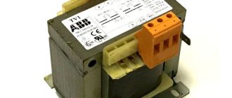
All the disadvantages of the above option are directly or indirectly related to the main design element - the transformer. Firstly, its weight and dimensions limit miniaturization. In order not to be unfounded, we will use as an example a step-down transformer 220/12 V with a rated power of 250 W. The weight of such a unit is about 4 kilograms, dimensions 125x124x89 mm. You can imagine how much a laptop charger based on it would weigh.
Step-down transformer OSO-0.25 220/12
Secondly, the price of such devices is sometimes many times higher than the total cost of the other components.
Pulse devices
As can be seen from the block diagram shown in Figure 3, the operating principle of these devices differs significantly from analog converters, primarily in the absence of an input step-down transformer.
Figure 3. Block diagram of a switching power supply
Let's consider the operating algorithm of such a source:
- Power is supplied to the network filter; its task is to minimize network noise, both incoming and outgoing, that arises as a result of operation.
- Next, the unit for converting sinusoidal voltage into pulsed constant voltage and a smoothing filter come into operation.
- At the next stage, an inverter is connected to the process; its task is related to the formation of rectangular high-frequency signals. Feedback to the inverter is carried out through the control unit.
- The next block is IT, it is necessary for automatic generator mode, supplying voltage to the circuit, protection, controller control, as well as the load. In addition, the IT task includes ensuring galvanic isolation between high and low voltage circuits.
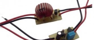
Unlike a step-down transformer, the core of this device is made of ferrimagnetic materials, this contributes to the reliable transmission of RF signals, which can be in the range of 20-100 kHz. A characteristic feature of IT is that when connecting it, the inclusion of the beginning and end of the windings is critical. The small dimensions of this device make it possible to produce miniature devices; an example is the electronic harness (ballast) of an LED or energy-saving lamp.
An example of miniature switching power supplies
- Next, the output rectifier comes into operation, since it works with high-frequency voltage; the process requires high-speed semiconductor elements, so Schottky diodes are used for this purpose.
- At the final phase, smoothing is performed on an advantageous filter, after which voltage is applied to the load.
Now, as promised, let’s look at the operating principle of the main element of this device – the inverter.
Output voltage regulation
If the power supply voltage needs to be regulated from zero, then the optimal circuit would be a parametric stabilizer with the addition of a variable resistor.
Smooth voltage regulation.
A 1 kOhm resistor connected between the base of the transistor and the common wire will protect the triode from failure if the potentiometer motor circuit breaks. When you rotate the variable resistor knob, the voltage at the base of the transistor will change from 0 to Ust of the zener diode with a lag of approximately 0.6 volts. It must be taken into account that the parameters of the node will be worse due to the use of a potentiometer - the presence of a moving contact (even of good quality) will inevitably reduce the voltage stability at the base of the transistor.
How to connect correctly
To ensure that the capacitors work correctly when independently assembling a 12V transformer power supply, the device is equipped with a resistor at the output with a resistance of 3 to 5 MΩ.
Voltage or current stabilizer
A standard type power supply is assembled using an electrolytic capacitor with a capacity of no more than 10,000 μF, a full-wave bridge rectifier made of diodes with a reverse voltage of 50 volts and a forward current of 3A, as well as a 0.5A fuse. A 7912 or 7812 capacitor is used as an integrated voltage stabilizer for 12V.
Zener diode
To ensure constant voltage output from the power supply, it is recommended to use a zener diode.
Integrated voltage stabilizer
Without the use of a voltage stabilizer, the power supply will not be able to function properly. The capacitors of the LM 78xx and LM 79xx series are used as these components. Zener diodes are selected according to the appropriate current and voltage parameters; there are a large number of them on the market, but the most advanced element is considered to be the KR142EN12 type.
The larger the capacitance of the capacitor, the better the output signal level; it has the correct shape and tends to a straight line.
Series LM 78xx
These voltage regulators have an output current of up to 1A, and an output voltage of: 5, 6, 8, 9, 12, 15, 18, 24. In addition, these capacitors have thermal overload protection and short circuit protection.
Series LM 79xx
These voltage regulators have similar values to the 78xx series. They also feature thermal protection against large overloads and short circuit protection.
Device layout
After all the components have been selected, or there is a clear idea of what they will be, you can begin to assemble the device. It is also important to understand what the future body of the device will be like. You can choose a ready-made one, or you can make it yourself if you have the materials and skills.
There are no special rules for the layout of components inside the housing. But it is advisable to arrange the nodes so that they are connected by conductors in series, as in the diagram, and over the shortest distance. It is better to place the output terminals on the side opposite the network cable. It is better to mount the power switch and fuse on the back wall of the device. To rationally use the inter-body space, some of the units can be installed vertically, but it is better to fix the diode bridge horizontally. When mounted vertically, convection currents of hot air from the lower diodes will flow around the upper elements and additionally heat them.
For those who don’t understand, watch the video: Simple DIY power supply.
Assembling a fixed supply DC power supply is not difficult. An average craftsman can do this; only basic knowledge of electrical engineering and minimal installation skills are needed.
Types and principle of operation of switching power supplies
The basic operating principle of a switching power supply (SMPS) is that direct voltage (rectified mains voltage or from a third-party source) is converted into pulsed voltage with a frequency of up to hundreds of kilohertz. Due to this, the winding parts (transformers, chokes) are light and compact.
Fundamentally, IIPs are divided into two categories:
- with pulse transformer;
- with storage inductance (it can also have secondary windings)
The former are similar to conventional transformer mains power supplies; their output voltage is regulated by changing the average current through the transformer winding. The latter work on a different principle - they are regulated by changing the amount of accumulated energy.
Based on other characteristics, IIP can be divided into unstabilized and stabilized, unipolar and bipolar, etc. These features are not of such a fundamental nature.
Driver
The use of a driver instead of a transformer unit is due to the peculiarities of the operation of the LED, as an integral element of modern lighting equipment. The thing is that any LED is a nonlinear load, the electrical parameters of which change depending on operating conditions.
Rice. 3. Current-voltage characteristics of the LED
As you can see, even with minor voltage fluctuations there will be a significant change in current. Powerful LEDs feel such differences especially clearly. There is also a temperature dependence in the operation, therefore, when the element is heated, the voltage drop decreases, and the current increases. This mode of operation has an extremely negative effect on the operation of the LED, causing it to fail faster. You cannot connect it directly from a mains rectifier, which is why drivers are used.
The peculiarity of the LED driver is that it produces the same current from the output filter, despite the size of the voltage supplied to the input. Structurally, modern drivers for connecting LEDs can be made using either transistors or a microcircuit. The second option is becoming increasingly popular due to better driver characteristics and easier control of operating parameters.
Below is an example of how the driver works:
Rice. 4. Driver circuit example
Here, a variable value is supplied to the input of the mains voltage rectifier VDS1, then the rectified voltage in the driver is transmitted through the smoothing capacitor C1 and the half-arm R1 - R2 to the BP9022 chip. The latter generates a series of PWM pulses and transmits it through a transformer to the output rectifier D2 and the output filter R3 - C3, which is used to stabilize the output parameters. Thanks to the introduction of additional resistors into the power supply circuit of the microcircuit, such a driver can regulate the output power value and control the intensity of the light flux.