In this article we will talk in detail about the need for a UPS for a heating pump, its types and design, its pros and cons, as well as what needs to be taken into account when choosing and purchasing one.
In many houses it is simply impossible to live without heating, so circulation pumps are installed in the houses, which drive water through pipes and then it gets to the radiators.
For stable operation of such equipment, it is necessary to ensure accurate and non-stop operation of the electricity supplied to it, because if the pump fails, then water will stop being pumped through the pipes, which can lead to water freezing in winter.
In order to avoid this problem with the equipment, it will be simply necessary to install an uninterruptible power supply (UPS, UPS) in the house.
Why does the circulation pump need a UPS?
The use of forced circulation of coolant in modern individual heating systems is not uncommon nowadays. The use of circulation pumps in autonomous heating systems not only significantly increases their productivity, but in some cases is the only way to provide heat to residential premises, for example, those with a large area or a multi-level structure.
A serious vulnerability of such heating systems is their energy dependence. It is obvious that even a short stoppage of coolant circulation equipment associated with power outages can lead to quite serious negative consequences.
An effective solution to the issue of quality and uninterruptible power supply for pumps used in heating, drainage and well systems is the use of uninterruptible power supplies (UPS). If there are interruptions in the power supply network, the “uninterruptible power supply” will ensure the correct operation of the pump and, accordingly, the heating system of the house.
Choosing a UPS for a circulation pump
For those who want to protect themselves from unexpected power outages, we have made a small selection of mandatory parameters that should be focused on first.
Outgoing current parameters
As mentioned above, a distinctive feature of a proper UPS is a clean or correct sine wave of the output signal. Deviations in the sinusoid are unacceptable. For the proper operation of a gas and solid fuel boiler with circulation pumps, such devices with dubious characteristics are absolutely unsuitable.
Before purchasing, you should look at the product data sheet and ask what type of sine wave this UPS has.
Starting power
For reliable operation of the UPS, it will be better if its power is sufficient to meet all the needs of the connected equipment. In this option, we are more interested in having enough power to operate the boiler circulation pump. It's best if UPS covers the stock by at least five times. And it’s even better if it is 7 times more than the calculated value.
You can find out the power consumption of an electric pump for a boiler room from its technical data sheet.
Installation location
It is better to place the UPS near existing outlets.
If it is not large, then it is not at all necessary to hang it on the wall, just place it on the nearest shelf. The main thing is not to block the ventilation holes. At the same time, do not forget to comply with the rules of the PUE. The minimum distances from gas pipes to sockets, including the UPS, must be at least 0.5 m.
Regarding the placement of batteries. Fashionable AGM models are afraid of elevated temperatures of more than 30 degrees. And near the boiler the temperature will clearly not be room temperature.
Therefore, place the battery as far as possible from heating pipes and hot boiler equipment.
What is an uninterruptible power supply?
An uninterruptible power supply for a circulation pump is a device that provides a constant supply of electrical energy. When the mains voltage decreases, the device begins to operate on one or more batteries.
The UPS consists of the following components:
- Stabilizer for the boiler. Allows you to prevent equipment breakdown due to voltage surges.
- Battery. Accumulates electrical energy, releasing it in case of disconnection from the network.
- Converter. Converts 12 V direct current into 220 volt alternating current.
- Filter. If there is a pulse converter, it blocks interference.
- Charge control indicator. Allows you to prevent critical discharge or overcharging of the device.
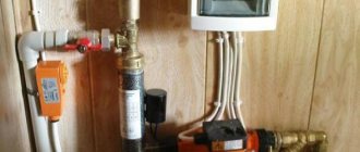
Appearance and design of the UPS for the circulation pump.
Criteria for selecting a UPS for a circulation pump
Voltage and power
The vast majority of pumps for domestic autonomous heating systems are single-phase devices with low power consumption (from several tens to several hundred watts). Thus, single-phase UPSs of appropriate power are suitable to power the pump motor.
However, when choosing an uninterruptible power supply, you should definitely take into account the short-term, but rather high starting currents of the pump motor, which can exceed its rated power consumption by 3-5 times. Considering the economical consumption of modern circulation pumps, in most cases it will be quite sufficient to use a UPS with a capacity of 500-1000 VA.
Battery life
In the UPS operating manuals, manufacturers indicate the value of this characteristic at full load. Obviously, the actual battery life depends on the power consumption of the pump motor and the capacity of the batteries used.
Modern UPSs with built-in batteries, as a rule, have the ability to increase capacity (and, accordingly, battery life) by connecting additional external batteries.
Models that do not have standard batteries at all will be more preferable in terms of selecting the required battery capacity. Equipped with more powerful chargers, such UPSs can work with external batteries of increased capacity, providing the necessary battery life for the uninterruptible power supply.
Output waveform
The ideal voltage for powering any load is a sinusoidal voltage or one with a curve as close as possible to a sinusoid. However, often at the output, the UPS inverter in autonomous mode forms, instead of the correct one, an approximated (stepped) sinusoid or even a meander (a periodic rectangular signal in each half-cycle of the sine graph). This waveform, with its strong sinusoidal distortion, is particularly unfavorable for the AC supply voltage of electric motors and power transformers.
The operation of a circulation pump in a network with a signal such as a modified sine wave leads to unacceptable heating of the magnetic circuit of the stator and rotor due to the occurrence of additional losses and eddy currents in them. This results in reduced service life or damage to the pump motor insulation and a high risk of premature failure.
Therefore, when choosing a UPS for a circulation pump, it is very important to pay attention to the output signal form stated in the manufacturer’s specifications. To power waveform-sensitive electric drives, it must be an ideal sine wave.
UPS type
Important technical characteristics that must first be taken into account when choosing the type of uninterruptible power supply to power the circulation pump are the speed of transition to autonomous operation and the shape of the output signal.
Devices with the best combination of such characteristics are double conversion UPS (online topology) and some line-interactive type models - their use for powering pumps is less preferable for a number of reasons.
Offline (or backup) UPSs, usually with a square wave output signal (or, at best, a highly modified sine wave), fundamentally cannot be considered as suitable power sources for electric motors (in our case, circulation pumps).
The most successful choice of the presented types of UPS will certainly be online topology devices. In addition to an ideal sine wave at the output and zero transition time to offline mode, the use of double conversion devices has the following advantages over line-interactive UPSs:
- a “pure sine” signal form is provided at the output both when the load is powered from the mains and in stand-alone mode (from the battery);
- constant stabilization of the network voltage and current frequency in combination with continuous filtering of high-frequency interference in the supply network;
- very efficient operation in networks with large dips and frequent voltage drops without switching to autonomous mode;
- possibility of connecting external batteries;
- the presence of a through zero for the correct operation of phase-dependent boilers;
- the ability to perform a “cold start” - starting the pump in the absence of voltage in the supply network (in autonomous mode).
What role does the starting moment play?
There are situations when motors are connected directly to the network, and switching is carried out using a conventional magnetic starter. To do this, linear voltage is applied to the windings, a rotating magnetic field of the stator is formed, due to which the equipment begins to operate.
In this case, it is impossible to avoid an inrush current, which in magnitude will exceed the rated current by 5-7 times. And the more powerful the engine and the higher the load, the longer the duration of such excess will be. More powerful motors demonstrate a long start, and the stator windings in them take a current overload longer.
Low power engines, not exceeding 3 kW, can easily withstand such changes. The network also copes quite well with short-term power surges, since the network in any case has a certain power reserve. This explains why small household electrical appliances, as well as small machines, fans and pumps are connected directly without worrying about them being overloaded. The stator windings in motors of low-power equipment are connected in a “star” when the calculation is for a 3-phase voltage of 380 volts or in a “triangle” when we are talking about 220 volts.
But if the engine is more powerful, with an indicator of 10 kW or more, then it is unacceptable to connect it directly to the network. It is necessary to limit the inrush current, otherwise you can provoke a significant overload, which will lead to dangerous consequences.
Operating principle of uninterruptible power supplies
An uninterruptible power supply for a heating pump (like any other) consists of a battery of one capacity or another (battery) and an automation unit. In normal mode, while the pump is powered from the mains, the electronic unit charges the UPS battery using the built-in charger and keeps it “in reserve”. When the standard voltage is lost, the same automation unit switches the consumer to power from the battery.
As a rule, the voltage and type of current required by the consumer differ from the voltage at the terminals of the backup battery, therefore almost any uninterruptible power supply contains an electronic converter - an inverter. Its task is to convert the DC voltage of the battery into that required to power the consumer (for a household circulation pump, usually 230 V / 50 Hz).
When the normal power supply is restored, the switchback occurs, and the battery is charged again. Thus, the UPS is always ready for operation and can supply power to the electrical machine at any time. How long can a UPS power the same circulation pump? Everything will depend on the battery capacity. There are uninterruptible power supply models with external batteries that can power the load for days.
One of the clear examples of such a system is a computer UPS. As soon as the mains voltage disappears, the computer will switch to battery power, giving the user time to correctly shut down and turn off the machine.
Criteria for selecting a backup power source
Backup power supplies designed to work with heating system pumps must be selected according to several characteristics:
- Power;
- Battery capacity;
- Acceptable battery life;
- Possibility of using external batteries;
- Input voltage variation;
- Output voltage accuracy;
- Time to switch to reserve;
- Output voltage distortion.
You should select a UPS for a circulation pump based on several basic parameters, the most important of which is power.
Determining the required UPS power
The electric motor, which is an integral part of the heating system pump, is an inductive reactive load. Based on this, the UPS power for the boiler and pump should be calculated. The technical documentation for the pump may indicate the power in watts, for example, 90 W (W). Thermal power is usually indicated in watts. To find out the total power, you need to divide the thermal power value by Cos ϕ, which can also be indicated in the documentation.
For example, the pump power (P) is 90W, and Cosϕ is 0.6. Total power is calculated using the formula:
Р/Cosϕ
Hence, the total power of the UPS for normal operation of the pump should be equal to 90/0.6=150W. But this is not the final result yet. When the electric motor starts, its current consumption increases approximately three times. Therefore, reactive power should be multiplied by three.
As a result, the UPS power for the heating circulation pump will be equal to:
P/Cosϕ*3
In the example given, the power supply will be 450 watts. If cosine phi is not indicated in the documentation, the thermal power in watts should be divided by a factor of 0.7.
Battery capacity
The capacity of the battery determines the time during which the heating system pump will operate in the absence of a network. The batteries built into the UPS usually have a small capacity, determined primarily by the size of the device. If the backup power source will operate under conditions of frequent and prolonged power outages, you should choose models that allow the possibility of connecting additional external batteries.
A very informative video about the personal experience of a person who was faced with purchasing an inverter for a boiler and heating pump, watch:
Input voltage
The mains voltage standard of 220 volts assumes permissible deviations of ± 10%, that is, from 198 to 242 volts. This means that all devices used on the territory of the Russian Federation must operate correctly within these limits. In fact, in various regions, and especially in rural areas, voltage deviations and surges can significantly exceed these values. Before purchasing a UPS for a heating pump, it will be very useful to measure the network voltage repeatedly throughout the day. The passport for the backup power supply indicates the permissible input voltage limits at which the device provides an output voltage close to the nominal value.
Output voltage and its shape
If the voltage parameters at the output of the uninterruptible power supply are within the permissible 10 percent, then this device is quite suitable for powering the heating system pump. The time it takes for the control board to switch to battery power usually does not exceed tens of microseconds. For an electric motor, this parameter is not critical.
A very important parameter of the UPS, necessary for the correct operation of the heating system pump, is the shape of the output signal. The pump electric motor requires a smooth sinusoid, which, of all models of backup power sources, can only be provided by a double conversion device or an on-line UPS. In addition to the ideal sine wave at the output, this source also produces an accurate voltage and frequency.
When installing a UPS for a heating pump, you should follow some rules:
- The room temperature must correspond to the values specified in the documentation;
- There should be no vapors of caustic reagents or flammable liquids in the room;
- The grounding circuit must be made in accordance with the operating rules for electrical installations.
An example of the possibility of starting a 380 V electric motor
It is required to check the possibility of starting an electric motor of type 4A250M2 U3 with a power of 90 kW. From the 6 kV busbars of the 2RP-1 substation, a substation with transformers of the TM type with a capacity of 320 kVA is powered. From the 2RP-1 substation to the TM-6/0.4 kV transformers with a 0% branch installed, an AAB cable with a cross-section of 3x70 mm2 is laid, the line length is 850 m. It is connected to the RU-0.4 kV busbars with an AAB cable with a cross-section of 3x95 mm2 , 80 m long engine type 4A250M2 U3.
Rice. 1 - Single-line diagram 0.4 kV
At the moment of starting the 4A250M2 U3 engine, the 4A250S2 U3 engine connected to the buses with a power of 75 kW and a terminal voltage of 365 V is running. The voltage on the 0.4 kV buses when starting the engine is Ush = 380 V.
- Mmax/Mn – multiple of the maximum torque;
- Mn/Mn – multiplicity of starting torque;
- Mn – rated motor torque;
1. Determine the long-term permissible current of motor D1:
2. Determine the starting current of motor D1:
where: Kstart = 7.5 – multiple of the starting current, according to the motor passport;
3. We determine the value of active and inductive resistance for an aluminum cable of the AAB brand with a cross-section of 3x70 mm2 for a voltage of 6 kV from the busbars of the 2RP-1 substation to a transformer of type TM 320 kVA, we take the resistance values from Table 2.5 [L2.s 48].
We obtain resistance values Rв = 0.447 Ohm/km and Хв = 0.08 Ohm/km.
These resistances must be brought to the low voltage side of the transformer since the motor is connected to the low voltage network. From Table 8 [L1, p. 93] for a nominal transformation ratio of 6/0.4 kV and a branch of 0% we find the value n=15.
4. We determine the active and inductive resistance of the cable in relation to the low voltage network using the formula [L1, p. 13]:
- Rv and Hv – network resistance on the higher voltage side;
- n = 6/0.4 =15 – transformation ratio of the step-down transformer.
5. Determine the resistance of a cable 850 m long from the 2RP-1 substation to the 6/0.4 kV transformer:
Rс = Rн*L = 0.002*0.85 = 0.0017 Ohm;
Xc = Xn*L = 0.000355*0.85 = 0.0003 Ohm;
6. We determine the resistance of a transformer with a power of 320 kVA, 6/0.4 kV according to Table 7 [L1, p. 92.93].
7. Determine the line resistance from the buses of the 2RP-1 substation to the low voltage buses of the substation:
Rsh = Rc + Rt = 0.0017 + 0.0097 = 0.0114 Ohm;
Xsh = Xc + Xt = 0.0003 + 0.0258 = 0.0261 Ohm;
8. Determine the resistance of an 80 m long AAB 3x95 mm2 cable from the low voltage busbars to the motor terminals:
where: R = 0.329 Ohm/km and X = 0.06 Ohm/km - the values of active and reactive resistance of the cable are determined from Table 2-5 [L2.s 48].
9. Determine the total resistance of the line from the 2RP-1 substation to the motor terminals:
Rd = Rsh + R1 = 0.0114 + 0.026 = 0.0374 Ohm;
Circulation pump design and UPS power requirements
The power supply requirements for circulation pumps and the requirements for uninterruptible power supplies for such pumps are determined by the design of the devices.
A modern circulation pump is a centrifugal pump with a water-cooled electric motor. Such pumps are also called “wet rotor” pumps. The following are mounted in a metal casing on a single shaft: an electric motor, an impeller with blades, a rotor, plain bearings, and control devices. A schematic representation of the design of the circulation pump is shown in the following figure.
The main design element of the circulation pump is the electric motor. Typically a highly efficient compact electric motor is used.
For these motors to operate properly, proper power supply must be provided. The electrical signal supplied to the windings of the electric motor must have the correct sinusoidal form. In the case of using power supplies with a modified sine wave, disturbances in the operation of the engine occur. In this case, the electric motor begins to heat up and hum. During long-term operation of the pump, additional wear occurs on the moving parts due to uneven rotation of the motor rotor.
In the case of a constantly reduced voltage (including at the UPS output), the current in the electric motor windings increases. The result is significant overheating of the electric motor and its failure. With reduced voltage, the circulation pump operates under increased load conditions, and a change occurs in the sound of the engine. Very low voltage may cause the pump to stall and prevent the pump from starting.
In case of increased voltage (including at the output of the UPS), the probability of breakdown of the pump motor windings increases. A significant increase in voltage leads to overheating of the pump and its failure.
A change in the frequency of the supplied current (including at the output of the UPS for the pump) leads to a change in the rotation speed of the circulation pump motor. As a result, uneven water supply leads to a reduction in the service life of the pump.
Anti-inrush current
Of course, the easiest way to start is when directly connected to the mains. However, inrush currents pose serious limitations in operation. This is a big drawback that is quite possible to combat.
- You can use a device that provides a soft start - this is the simplest and most effective way. Its only drawback is the high cost of the converters. There are even pump models that already have this mechanism built into them. The principle of its operation is that the tension increases gradually. Thus, the rotor spins, and the load on the electrical network remains virtually unchanged.
- Installation of a transformer that uses several windings. This implies a step-by-step switching on (for standard pumps, one or two sections limiting currents are enough). After the pump starts to work faster, they alternately leave the circuit. The first voltage reduction is performed by a maximum of half of the total.
- If a three-phase motor is used, the power of which exceeds 300 W, the use of a star-delta starting circuit is allowed. At startup, a “star” is connected, which reduces the starting currents by 3 times, and after the device has accelerated, the “triangle” is turned on.
Source of the article: https://avantigeo.ru/puskovye-toki-dvigateley-skvazhinnyh-nasosov/
Factory models
You can buy an uninterruptible power supply suitable for its characteristics in heating and plumbing stores. They are also sold in online stores. Final prices vary depending on the manufacturer, type of equipment and technical specifications. We will look at the most popular models and give their estimated cost.
Energy PN-1000 with 75 A battery
We have a simple uninterruptible power supply with a good battery capacity of 75 A/h. With a pump power of 100 W, the battery life will be about 8 hours. The peak power is 1000 W, which is enough for any reactive load. At the output, the device produces a pure sine wave. And it refers to line-interactive UPSs, characterized by high efficiency and an affordable price. The cost of the model on the domestic market is about 260,000 rubles.
Modifications with different battery capacities are also available for sale:
- At 100 A/h – up to 11 hours when operating with a load of 100 W;
- At 55 A/h – up to 6 hours when operating with a load of 100 W;
- At 200 A/h - up to 23 hours when operating with a load of 100 W.
If power outages in your area are frequent and long-lasting, we recommend paying attention to the latest modification - its cost is 36-37 thousand rubles.
SVC DI-600-F-LCD
A compact uninterruptible power supply that can work with boilers and pumps, ensuring continuous circulation of coolant in the heating system. It belongs to the category of linear-interactive and produces a pure sine wave at the output without any distortion. The equipment does not require user intervention in its operation and provides an output voltage error of no more than 10% - this is the norm for pumps, but for boilers it could be less. The speed of switching to operation from the battery does not exceed 20 ms.
There is no built-in battery here; an external battery with a capacity of up to 200 A/h is connected to the uninterruptible power supply - this will ensure up to 24 hours of autonomous operation of the heating system. The peak load for this model should not exceed 360 W. The estimated cost of the model is 6.5-7 thousand rubles.
Tieber T-1000
If you need an uninterruptible power supply with a maximum capacity, from which the pump can operate for up to two days, you should look at this model. It works with two batteries with a capacity of up to 200 A/h each. The manufacturer recommends using maintenance-free gel batteries, as they do not emit harmful gases into the atmosphere - this is important for residential premises.
The maximum load power is 800 W. An uninterruptible power supply can power fairly powerful pumps and heating boilers, as well as units of water heated floors. The output voltage form is a pure sine wave, as required by pumping equipment motors. The device is designed for floor installation; batteries are placed next to it. The maximum charging current is 12 A/h.
Multiplier system
This is an approximate relationship for motors installed after drilling a well for one and three phases with different powers and an acceleration period of 1/10 s.
| Power, W) | Single-phase motor operating current (A) | Single-phase motor, starting multiplier | Three-phase motor operating current (A) | Three-phase motor, starting multiplier |
| 370 | 3,95 | 3,4 | 1,4 | 3,7 |
| 550 | 5,8 | 3,5 | 2,2 | 3,5 |
| 750 | 7,45 | 3,6 | 2,3 | 4,7 |
| 1100 | 7,3 | 4,3 | 3,4 | 4,6 |
| 1500 | 10,2 | 3,9 | 4,2 | 5 |
| 2200 | 14 | 4,4 | 5,5 | 4,7 |
Based on the data in the table, at first it may seem strange that the amount of electricity consumption does not correspond to the power. In fact, companies that manufacture motors usually indicate the power that characterizes the pump shaft. This power is primarily affected by efficiency, and its value is less than the power of electricity consumed. In this case, the current value is taken that characterizes operation at full load.
Typically, the pump can only be turned on a certain number of times in 60 minutes. This is due to the fact that a large amount of thermal energy is released on the winding when turned on. If you ignore this rule, overheating will occur. When overheating becomes critical, the insulation will lose its properties, a short circuit will occur between the turns and the pump will become completely inoperative.
Wall-mounted and floor-standing online UPS “Shtil” for pumps
The use of the Shtil single-phase UPS models recommended below guarantees a high level of uninterrupted power supply and operational reliability of not only circulation pumps and electronically controlled heating boilers, but also any other power-sensitive electrical equipment of engineering systems in city apartments, private residential buildings or offices.
Model range of wall-mounted online UPS
The SW series is represented by fairly compact low-power devices - 250 VA, 500 VA and 1 kVA. This output power, even taking into account the high starting currents of the electric motors, several times higher than the rated ones, will be quite sufficient to power any circulation pump of the heating system.
New UPS SW250SL (250 VA) Active power, kW 0.225 Form factor on-line topology (double conversion) Limit input voltage range, V90-295 Nominal output voltage, V230 Output voltage setting range, V210-240 (requires IC-SNMP/Web monitoring card or IC-SNMP/mini-USB) Accuracy of output voltage stabilization, % ± 2 Output voltage shape pure sine wave Maximum output current, A1.2 Availability of built-in batteries Electronic automatic bypass Warranty period, months 24 Get a manual 16,200 ₽ Add to cart New UPS ST250 (250 VA) Active power, kW0.225 Form factor floor-standing Topology on-line (double conversion) Limit input voltage range, V90-295 Nominal output voltage, V230 Output voltage setting range, V210-240 (requires IC-SNMP/Web or IC-SNMP/mini-USB monitoring card) Accuracy output voltage stabilization, % ± 2 Output voltage form pure sine wave Maximum output current, A1.2 Presence of built-in batteries (optional) Electronic automatic bypass Warranty period, 24 months Get a manual 18,900 ₽ Add to cart New UPS SW250 (250 VA) Active power, kW 0.225 Form factor wall-mounted ologyon- line (with double conversion) Limit input voltage range, V90-295 Nominal output voltage, V230 Output voltage setting range, V210-240 (requires IC-SNMP/Web or IC-SNMP/mini-USB monitoring card) Output voltage stabilization accuracy, %± 2Output voltage form pure sine waveMaximum output current, A1.2Presence of built-in batteries (optional)Electronic automatic bypass Warranty period, months 24 Get a manual 16,480 ₽ Add to cart New UPS SW250LD (250 VA) Active power, kW0.225Form factor wall-mounted Topology on-line (with dual transformation) Limit input voltage range, V90-295 Nominal output voltage, V230 Output voltage setting range, V210-240 (requires IC-SNMP/Web or IC-SNMP/mini-USB monitoring card) Output voltage stabilization accuracy, %±2 Output voltage shape pure sine wave Maximum output current , A1,2 Availability of built-in batteries no Electronic automatic bypass Warranty period, months 24 Get the manual 17,580 ₽ Add to cart UPS SW500SL (500 VA) Active power, kW 0.4 Form factor wall-mounted Topology on-line (with double conversion) Limiting input voltage range, V 90-295 Nominal output voltage, V220 Output voltage setting range, V220-240 Accuracy of output voltage stabilization, % ± 2 Output voltage shape pure sine wave Maximum output current, A2.3 Availability of built-in batteries Electronic automatic bypass Warranty period, months 24 Get manual 21,280 ₽ Add to cart
Sources
- https://www.shtyl.ru/support/articles/osobennosti-vybora-ibp-dlya-nasosa/
- https://VashUmnyiDom.ru/elektropitanie/ups/besperebojnik-dlya-nasosa-otopleniya.html
- https://bespereboynik.ru/dlya-nasosov/
- https://OmShantiDom.ru/montazh-i-remont/ibp-dlya-cirkulyacionnogo-nasosa.html
- https://Acums.ru/bespereboyniki-i-bloki-pitaniya/dlya-nasosa-otopleniya-tsirkulyatsionnogo-kak-vybrat-ibp-kakoy-akkumulyator
- https://nasos-kitai.ru/proizvoditeli-nasosov/besperebojnik-dlya-nasosa-otopleniya-i
- https://teplo.bast.ru/articles/ibp-cirkulyacionnogo-nasosa-otopleniya
- https://remont-system.ru/komplektuyushchie/bespereboynye-bloki-pitaniya-dlya-cirkulyacionnyh-nasosov
[collapse]