Electric motor power calculation
The conversion of electrical energy into kinetic energy is carried out using various types of electric motors. These devices are widely used in modern production and in everyday life. Most often, electric motors serve as electric drives for machines and mechanisms and are used to ensure the operation of pumping equipment, ventilation systems and many other units and devices. In connection with such a wide application, the calculation of electric motor power is of particular relevance. For these purposes, many different methods have been developed that allow calculations to be performed in relation to specific operating conditions.
Ratio of torque M [Nm] and useful power on shaft P2 [kW]
You can compare the developed torque (M [Nm]) and the net power of the electric motor in kW in the following way:
The calculation formulas look like this.
- Total motor power:
- For DC electric motor.
- When choosing an AC motor.
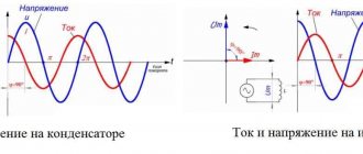
2. Active and Reactive power
An important point: if the reactive power is negative when calculated for specific operating conditions, it means that the electric motor supplies it to the network.
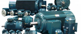
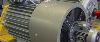
Main types of electric motors
There are many types and modifications of electric motors. Each of them has its own power and other parameters.
The main classification divides these devices into DC and AC motors. The first option is used much less frequently, since its operation requires the presence of a direct current source or a device that converts alternating voltage into direct current. Fulfilling this condition in modern production will require significant additional costs.
But, despite significant disadvantages, DC motors have a high starting torque and operate stably even at high overloads. Due to their qualities, these units are widely used in electric transport, in the metallurgical and machine tool industries.
However, most modern equipment runs on AC motors. The operation of these devices is based on electromagnetic induction, which is created in a magnetic field by a conducting medium. The magnetic field is created using windings flowing around currents or using permanent magnets. Electric motors operating on alternating current can be synchronous or asynchronous.
The use of synchronous electric motors is practiced in equipment where a constant rotation speed is required. These are DC generators, pumps, compressors and other similar installations. Different models differ in their own technical characteristics. For example, the rotation speed can be in the range of 125-1000 rpm, and the power reaches 10 thousand kilowatts.
Many designs have a short-circuited winding located on the rotor. With its help, if necessary, an asynchronous start is made, after which the synchronous motor continues to operate as usual, minimizing electrical energy losses. These engines are characterized by their small size and high efficiency.
Asynchronous AC motors have become much more widespread in the manufacturing sector. They are characterized by a very high frequency of rotation of the magnetic field, significantly exceeding the speed of rotation of the rotor. A significant disadvantage of these devices is considered to be a decrease in efficiency to 30-50% of the norm at low loads. In addition, during start-up, the current parameters become several times greater compared to operating indicators. These problems are eliminated by using frequency converters and soft starters.
Asynchronous motors are used in those facilities where frequent switching on and off of equipment is required, for example, in elevators, winches, and other devices.
Starting current
The rated current is determined as follows:
For direct current mechanisms.
For three-phase synchronous and asynchronous.
Explication of formulas:
- PH — electric motor power (nominal, according to the passport);
- ηH—electric motor efficiency (in technical documentation);
- cosfH is a relative indicator of electric motor power;
- UH is the voltage of the electric motor (nameplate, nominal).
Selecting an electric motor based on voltage begins with an analysis of the parameters of the power supply network at a particular enterprise. At high power levels, you should not choose a device with low voltage. This will require significant additional investments, often unjustified (from copper supply wires to switches).
The preferred connection scheme in most cases is “star”. Unlike the “triangle”, it does not have a zero-sequence circuit (reduces efficiency and leads to strong heating of the elements). In circuits of a squirrel-cage asynchronous motor, where starting with switching from star to delta can be used, all 6 terminals of the stator winding must be brought into the terminal box. This is necessary to reduce the starting load. And it is applicable when the moment of resistance to it at the start is small.
Calculation of electric motor power for a pump
The choice of electric motor for a pumping installation depends on specific conditions, first of all, on the water supply scheme. In most cases, water is supplied using a water tank or a water boiler. Centrifugal pumps with asynchronous motors are used to drive the entire system.
The selection of the optimal pump power is carried out depending on the need for fluid supply and pressure. The QH pump flow is measured in liters delivered per hour and is designated as l/h. This parameter is determined by the following formula: Qn = Qmaxch = (kch x kday x Qav.day) / (24 η), where Qmaxch is the possible maximum hourly water flow rate, l/h, kch is the coefficient of unevenness of hourly flow, kday is the coefficient of unevenness daily flow rate (1.1 - 1.3), η - efficiency of the pumping unit, taking into account water losses), Qavg.day - value of the average daily water flow rate (l/day).
The optimal water pressure should ensure its supply to the specified location, subject to the required pressure. The required parameters of the pump pressure (Hntr) depend on the suction height (Hvs) and the discharge height (Nng), which together determine the indicators of static pressure (Hs), losses in pipelines (Hp) and the pressure difference between the upper (Pvu) and lower (Pnu) levels.
Based on the fact that the pressure value will be equal to H = P/ρg, where P is pressure (Pa), ρ is the density of the liquid (kg/m3), g = 9.8 m/s2 is the acceleration of free fall, g is the specific liquid weight (kg/m3), the following formula is obtained: Hntr = Hc + Hp + (1/ρ) x (Pvu – Rnu).
After calculating the water flow and pressure from the catalog, you can already select a pump with the most suitable parameters. In order not to be mistaken with the power of the electric motor, it must be determined by the formula: Pmod = (kз x ρ x Qн x Нн) / (ηн x ηп), where kз is a safety factor depending on the power of the pump motor and is 1.05 – 1, 7. This indicator takes into account possible water leaks from the pipeline due to loose connections, pipeline breaks and other factors, so electric motors for pumps must have some power reserve. The higher the power, the lower the safety factor can be assumed.
Calculation of engine power formula for compressor
When choosing an electric motor that is most suitable for the operation of a particular compressor, it is necessary to take into account the long-term operation of this mechanism and the constant load. The required power of the RDV engine is calculated in accordance with the power on the shaft of the main mechanism. In this case, the losses arising in the intermediate link of the mechanical transmission should be taken into account.
Additional factors are the capacity, purpose and nature of the production where the compressor equipment will be operated. They have an impact and the equipment may require minor but ongoing adjustments to maintain proper performance.
The engine power can be determined using the formula: , in which:
- Q – compressor performance or flow value (m 3 /s);
- A – work to perform compression (J/m 3 );
- ηк – indicator efficiency (0.6-0.8) to take into account power losses during real air compression;
- ηп – mechanical efficiency (0.9-0.95) taking into account the transmission between the engine and the compressor;
- kz – safety factor (1.05-1.15) to take into account factors that cannot be calculated.
Work A is calculated using a separate formula: A = (Au + Aa)/2, where Au and Aa represent isothermal and adiabatic compression, respectively.
The value of the work that must be done before the required pressure appears can be determined using the table:
Electric motor power calculation
Electric motor power by current can be calculated using our online calculator:
The result can be rounded to the nearest standard power value.
Standard values of electric motor power : 0.25; 0.37; 0.55; 0.75; 1.1; 1.5; 2.2; 3.0; 4.0; 5.5; 7.5; eleven; 15; 18.5; 22; thirty; 37; 45; 55; 75 kW, etc.
Engine power is calculated using the following formula:
P=√3UIcosφη
- U - Rated voltage (voltage to which the electric motor is connected);
- I - Rated current of the electric motor (taken from the passport data of the electric motor , and in their absence is determined by calculation);
- cosφ - Power factor - the ratio of active power to total power (taken from 0.75 to 0.9 depending on the power of the electric motor);
- η - Efficiency factor - the ratio of the electrical power consumed by the electric motor from the network to the mechanical power on the motor shaft (taken from 0.7 to 0.85 depending on the power of the electric motor);
Calculation formula for fans
Fans are widely used in a variety of fields. General purpose devices operate in clean air, at temperatures below 800. Air with a higher temperature is moved using special heat-resistant fans. If you have to work in an aggressive or explosive environment, in these cases models of anti-corrosion and explosion-proof devices are used.
In accordance with the principle of operation, fan units can be centrifugal or radial and axial. Depending on the design, they develop pressure from 1000 to 15000 Pa. Therefore, the power required to drive the fan is calculated in accordance with the pressure that needs to be created.
For this purpose, the formula is used: Nв = Hв·,Qв/1000·, efficiency, in which Nв the power required for the drive (kW), Hв the pressure created by the fan (Pa), Qв the moved volume of air (m3/s), efficiency efficiency.
To calculate the power of the electric motor, the formula is used :, where the parameter values will be as follows:
- Q unit productivity,
- N output pressure,
- &eta, in fan efficiency,
- &eta,n - transmission efficiency,
- short-circuit safety factor depending on the power of the electric motor. With a power of up to 1 kW, short circuit = 2, from 1 to 2 kW short circuit = 1.5, at 5 kW and above short circuit = 1.1-1.2.
This formula allows you to calculate the power of electric motors for centrifugal and axial fans. For centrifugal structures, the efficiency is 0.4-0.7, and for axial ones 0.5-0.85. Other design characteristics are available in special catalogs for all types of electric motors.
The power reserve should not be too large. If it is too large, the efficiency of the drive will noticeably decrease. In addition, AC motors may experience a reduction in power factor.
Motor current calculation
The rated and starting current of an electric motor can be calculated by power using our online calculator:
The rated motor current is calculated using the following formula:
Inom=P/√3Ucosφη
- P - Rated power of the electric motor (taken from the motor’s passport data or determined by calculation);
- U - Rated voltage (voltage to which the electric motor is connected);
- cosφ - Power factor - the ratio of active power to total power (taken from 0.75 to 0.9 depending on the power of the electric motor);
- η - Efficiency factor - the ratio of the electrical power consumed by the electric motor from the network to the mechanical power on the motor shaft (taken from 0.7 to 0.85 depending on the power of the electric motor);
The starting current of the electric motor is calculated using the formula:
Istart=Inom* K
- K - Starting current multiplicity, this value is taken from the electric motor passport, or from catalog data (in the above online calculators, the starting current multiplicity is determined approximately based on the other specified characteristics of the electric motor).
Reasonable choice of electric motor based on power
The choice of electric motor in terms of power depends on the specific operation of the equipment to which it is connected. Loads are assessed based on the nominal mode and changes in power consumption. In this case, the calculated value should ensure the operation of the electric motor:
- with normal heating;
- sufficient starting torque;
- overload capacity within established limits.
It will be considered correct to choose an electric motor according to the power at which it, accepting the loads provided for by the technical process, will heat up no higher than the permissible temperature for each of the main parts of the assembly. The wrong choice is one with a large resource reserve, which leads to underutilization of productivity, which means overpayments for the maintenance of a more expensive model, its repair, and reduced relative performance indicators (including efficiency).
Calculation of electric motor power factor
Online calculation of power factor (cosφ) of an electric motor
Calculation of cosφ (cosine phi) of the engine is carried out using the following formula:
cosφ=P/√3UIη
- P - Rated power of the electric motor (taken from the motor’s passport data or determined by calculation);
- U - Rated voltage (voltage to which the electric motor is connected);
- I - Rated current of the electric motor (taken from the passport data of the electric motor , and in their absence is determined by calculation);
- η - Efficiency factor - the ratio of the electrical power consumed by the electric motor from the network to the mechanical power on the motor shaft (taken from 0.7 to 0.85 depending on the power of the electric motor);
Operating modes of electric motors
The load on the electric motor is determined by its operating mode. It may remain unchanged or change depending on operating conditions. When choosing an engine, the nature and significance of the expected load must be taken into account. Taking this factor into account, the electric motor power is calculated.
Modes in which electric motors operate:
- S1 continuous mode. The load does not change during the entire period of operation. The engine temperature reaches the set value.
- S2 short-term mode. In this case, during operation the temperature does not have time to reach the desired value. When switched off, the engine cools down to ambient temperature.
- S3 periodic-short-term mode. During engine operation, periodic shutdowns occur. During these periods, the engine temperature cannot reach the desired value or become the same as in the environment. When calculating the engine, including power, all pauses and losses and their duration are taken into account. One of the important criteria for choosing a unit is the permissible number of starts for a certain period of time.
- S4 periodic-short-term mode with frequent starts.
- S5 - periodically-short-term mode with electric braking. Both modes S4 and S5 work the same as S3.
- S6 periodic-continuous mode with short-term load. The engine is operated under load, which alternates with idling.
- S7 periodic-continuous mode with electric braking.
- S8 is a periodic-continuous mode in which the load and rotation speed change simultaneously.
- S9 mode, when the load and rotation speed do not change periodically.
Calculation of electric motor efficiency
Online calculation of efficiency (efficiency) of an electric motor
The efficiency of the electric motor is calculated using the following formula:
η=P/√3UIcosφ
- P - Rated power of the electric motor (taken from the motor’s passport data or determined by calculation);
- U - Rated voltage (voltage to which the electric motor is connected);
- I - Rated current of the electric motor (taken from the passport data of the electric motor , and in their absence is determined by calculation);
- cosφ - Power factor - the ratio of active power to total power (taken from 0.75 to 0.9 depending on the power of the electric motor);
Did you find these online calculators useful? Or maybe you still have questions ? Write to us in the comments!
Didn’t find an article on the website on a topic that interests you regarding electrical engineering? Write to us here. We will definitely answer you.
DC motors
Based on Newton's principle of mechanics, which states that all motion is relative, a DC electric motor can be called a synchronous machine. Although the magnetic fields of the stator and rotor are stationary in it, the rotation of the shaft occurs due to the effect of repulsion of like poles of magnets and attraction of unlike poles.
Their position relative to each other is synchronized by a special device - a collector located on the rotor shaft. This is a copper ring divided into sectors by a dielectric. The ends of the rotor windings are connected to these sectors and create contact pairs.
They are supplied with direct current through carbon brushes. As the shaft rotates, poles switch between pairs. The stator magnetic field can be created by metals with residual magnetism or by the passage of current through the windings. The latter are used in high-power electric machines.
Their advantage is a high efficiency, up to 98%, as well as consistently high torque and low dependence on overloads. DC motors are excellent for driving lifting mechanisms, as well as for traction in electric vehicles.
They are very easy to control: to reduce the rotation speed, you just need to reduce the amount of applied voltage, and to reverse it, just change the polarity. The disadvantage is the complexity of the device and the low reliability of the brush assembly, its tendency to spark and be noisy. In addition, DC voltage is difficult to transmit over long distances, which is why there are no main lines of this type. You will have to create the power yourself, using rectifier or inverter circuits. You can also read about DC motors here.
Brushed motors
They are similar in design to DC motors. However, they are powered by single-phase alternating current. Their stator field winding is connected in series with the armature winding. The rotation of the shaft occurs due to the synchronous change of poles of the magnetic field in the stator and rotor windings.
The advantages listed above - high torque, insensitivity to overloads - also include the fact that this is the only AC electric machine that can be controlled without problems.
To change the shaft rotation speed, it is enough to reduce the supply voltage, and to reverse it, swap the connection points of the collector unit with the stator winding. Therefore, commutator motors are widely used in household electrical appliances.
For example, in washing machines, drills and other electrified tools. The disadvantages, the main of which is the complexity and low reliability of the brush assembly, include the inability to connect three-phase voltage. Simply because in this case there should be six brushes. This limits the maximum power of the motors: for single-phase machines at a voltage of 220 volts, this value does not exceed 2.5 kilowatts.
AC synchronous motors
Their stator winding is powered by three-phase alternating current, and the rotor winding is powered by direct current. In order for their magnetic poles to mesh and cause the shaft to move, such an electric motor must be spun manually or by another motor. In fact, they are an alternator operating in rotation mode. The advantage of the machine is high torque and stable rotation speed.
Asynchronous electrical machines
In them, the magnetic field of the rotor is a product of the rotating magnetic field of the stator. Since there is an air gap between these machine parts, energy transfer between them occurs with losses. Therefore, the phase of the current in the rotor lags behind the phase of the current in the stator by a small angle (no more than 100), which determines the value of the power factor cosφ. This lag is the reason why an electric machine of this type is called asynchronous.
Squirrel-cage motors
Their rotor winding is a set of metal rods that connect two rings. The resulting figure is called a “squirrel wheel”. At the moment voltage is applied to the stator winding, a short circuit current arises in the rotor, the energy of which is spent on unwinding the shaft and is thereby extinguished. It has a slightly lower efficiency than synchronous machines, it does not exceed 80%.
After gaining speed, it has a very stable torque on the shaft and can withstand overloads well. The main advantages of such engines are their simplicity and reliability, thanks to which they are very widespread. Disadvantages: complexity of management.
To change the rotation speed, it is necessary to change the frequency of the supply voltage or the number of stator windings, which determines the number of poles of the electromagnet - the more there are, the lower it is. Also, electric motors with a squirrel-cage rotor are characterized by a large starting current that overloads the network, as well as a sharp increase in torque when power is connected, which can cause damage to the drive gearbox.
Wound rotor motors
The start-up of high-power squirrel-cage asynchronous motors (more than 30 kW) is associated with extreme overload of the supply network. To eliminate this phenomenon, machines with a wound rotor are used, the winding of which consists of three coils connected by a star. Their ends are connected by carbon brushes to three slip rings located on the motor axis.
Unlike a DC motor commutator, they are not divided into sectors. When starting such a machine, a three-phase rheostat is used, the resistance of which is maximum at the moment of start-up. By gradually reducing the active resistance of the rotor, a smooth rotation of the electric motor shaft is achieved. When the nominal speed is reached, it is short-circuited.
By changing the rotor resistance, you can change the rotation speed. The advantage of a machine of this type is the absence of overload at the time of start-up and a smooth increase in torque. Therefore, it is used in lifting equipment. The disadvantage is the complexity of the device and lower efficiency than that of machines with a squirrel-cage rotor, it is no more than 60%.