Is it possible to control engine speed with a dimmer?
To regulate the rotation speed of single-phase electric motors with a supply voltage of 220 V, triac rotation speed controllers are used. The dimmer (triac dimmer), in turn, is designed to control a resistive load and should be used only as a regulator of lamp brightness.
Interesting materials:
How to make a big clock on the lock screen? How to make a big clock on a computer? How to make a large hole in thick metal? How to make a large parenthesis in Word? How to make a Wither boss? How to make a bot an admin in a conversation? How to make a bracelet on a fishing line? How to make it the default browser? How to make a doghouse for a German Shepherd with your own hands? How to make a booklet for a project in Word?
Creating a regulator yourself
Factory regulators are presented in a wide range, both on the Internet and in regular stores. But, if you have no desire to purchase a ready-made component and want to assemble it yourself, this can actually be done. For the task to be successful, it is necessary to follow the design algorithm and have all the necessary components available.
We will need:
- wiring;
- ready-made diagram;
- capacitor circuits;
- thyristor;
- resistor;
- soldering iron
Based on the layout diagram, the power and rotation regulator will be responsible for controlling the first half-cycle. A homemade stabilizer has the following operating algorithm (example of our model):
- the device connected to a standard 220V power supply receives current to the capacitor;
- the component fires immediately after receiving a charge;
- load transfer to resistors and bottom cables;
- connecting the positive capacitor contact to the thyristor electrode;
- supplying one voltage charge at a sufficient level;
- discovery of a second semiconductor;
- the capacitor supplies the thyristor with a load, which in turn passes it through itself;
- the capacitor is discharged;
- half-cycle repetition;
If the power of a DC or AC motor is high, the regulator ensures economical operation of the device. There is enough power and resource to use the device in your household. But, when you need to regulate speed without loss of power and larger and more productive units, then you should still pay attention to factory modifications. Despite the fact that this option will be more expensive, it will ensure 100% performance and reliability.
Now let's look at other, non-standard, but quite common methods of adjustment and stabilization.
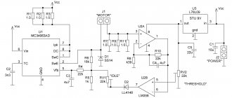
Method 2
It uses a TDA 1085 type chip with a standard board. You can, if you wish, create your own by “upgrading” and changing inappropriate elements. For example, you can use a double-sided printed circuit board. Capacitor and resistor parts can be used for surface mounting. It is recommended to separate low- and high-voltage circuits from each other. And the “ground” must be distributed taking into account the parameters of the microcircuit.
An example of an assembled board
The result is a compact, double-sided board that provides precise control.
Methods for controlling the speed of an IM with a wound rotor
The rotation speed of an IM with a wound rotor is changed by changing the slip. Let's look at the main options and methods.
Changing the supply voltage
This method is also used for IMs with a short-circuit rotor. The asynchronous motor is connected through an autotransformer or LATR. If you reduce the supply voltage, the engine speed will decrease.
But this mode reduces the overload capacity of the engine. This method is used for regulation within a voltage range not higher than the rated voltage, since an increase in the rated voltage will lead to failure of the electric motor.
Active resistance in the rotor circuit
When using this method, a rheostat or a set of high-power constant resistors is connected to the rotor circuit. This device is designed to smoothly increase resistance.
Slip increases in proportion to the increase in resistance, and the rotation speed of the electric motor shaft decreases.
Advantages:
- large range of regulation towards lower rotation speed.
Flaws:
- decrease in efficiency;
- increase in losses;
- deterioration of mechanical characteristics.
Asynchronous valve cascade and dual-fed machines
Changing the operating speed of asynchronous electric motors in these cases is done by changing the slip. In this case, the rotation speed of the electromagnetic field remains unchanged. Voltage is supplied directly to the stator windings. The adjustment occurs through the use of sliding power, which is transformed into the rotor circuit and forms an additional EMF. Such methods are used only in special machines and large industrial devices.
Types and selection criteria
To select a regulator, you need to be guided by certain characteristics for a particular case. Among all the criteria, you can choose the following:
- By type of control. For commutator-type motors, regulators with a vector or scalar control system are used.
- Power is the main parameter from which you need to build.
- By U band.
- By frequency range. You need to choose a model that meets the user's requirements for a particular case.
- Other characteristics, which include warranty, dimensions, equipment.
In addition, the regulator is selected more powerful than the electric motor itself according to the formula: Preg = 1.3 * Pmot (Preg, Pmot is the power of the regulator and the motor, respectively). It must be selected for different U ranges, since versatility plays an important role.
Thyristor device
This model, shown in Diagram 1, uses 2 thyristors connected back-to-back, although they can be replaced with one triac.
Scheme 1 - Thyristor speed control of a commutator motor without loss of power.
This circuit performs regulation by opening or closing thyristors (triacs) during a phase transition through the neutral. To correctly control a commutator motor, the following methods of modifying circuit 1 are used:
- Installation of LRC protective circuits consisting of capacitors, resistors and chokes.
- Adding capacitance at the input.
- The use of thyristors or triacs, the current of which exceeds the rated value of the motor current in the range of 3..8 times.
This type of regulator has advantages and disadvantages. The first include low cost, low weight and dimensions. The second ones include the following:
- application for low power motors;
- there is noise and jerking of the motor;
- when using a circuit based on triacs, a constant U hits the motor.
This type of regulator is installed in fans, air conditioners, washing machines and electric drills. Performs its functions perfectly, despite its shortcomings.
Transistor type
Another name for a transistor-type regulator is an autotransformer or PWM regulator (scheme 2). It changes the value of U according to the principle of pulse width modulation (PWM) using an output stage that uses IGBT transistors.
Scheme 2 - Transistor PWM speed controller.
Switching of transistors occurs at a high frequency and thanks to this it is possible to change the width of the pulses. Consequently, the value of U will also change. The longer the pulse and the shorter the pause, the higher the value of U and vice versa. The positive aspects of using this variety are as follows:
- Low weight of the device with small dimensions.
- Quite low cost.
- At low speeds there is no noise.
- Control via low U values (0..12 V).
The main disadvantage of the application is that the distance to the electric motor should be no more than 4 meters.
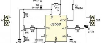
Frequency regulation
Regulating the speed of motors of various types due to frequency is widely used. Frequency conversion occupies a leading position in the market for sales of speed control devices and soft starting. Thanks to its versatility, it is possible to influence the power, performance and speed of any device with an electric motor. These devices are used for single-phase and three-phase motors. The following types of frequency converters are used:
- Specialized single-phase.
- Three-phase without capacitor.
To regulate the speed, a capacitor is used, connected to the windings of a single-phase motor (diagram 3). This frequency converter (FC) has a capacitive R, which depends on the frequency of the flowing alternating current. The output stage of such an inverter is made of IGBT transistors.
Scheme 3 - Frequency speed controller.
A specialized inverter has its advantages and disadvantages. The advantages are the following:
- Blood pressure control without human intervention.
- Stability.
- Additional features.
It is possible to control the operation of the electric motor under certain conditions, as well as protection against overloads and short-circuit currents. In addition, it is possible to expand the functionality by connecting digital sensors, monitoring operating parameters and using a PID controller. The disadvantages include limitations in frequency control and a fairly high cost.
For three-phase IM, frequency control devices are also used (Scheme 4). The regulator has three phases at the output for connecting an electric motor.
Scheme 4 - inverter for a three-phase motor.
This option also has its strengths and weaknesses. The first include the following: low cost, choice of power, wide range of frequency regulation, as well as all the advantages of single-phase frequency converters. Among all the negative aspects, the main ones can be identified: preliminary selection and heating during startup.
How to determine the power of an electric motor?
The easiest way to determine the rated power of an electric motor is by looking at the nameplate. It indicates the mechanical power (shaft power), the value of which is always less than the power consumption due to losses due to friction and heating. However, if there is no nameplate on the motor housing, you can very roughly estimate the characteristics of the drive based on its dimensions. With the same power, an engine with a larger shaft diameter will have higher shaft power and a lower speed.
Also, power can be determined by the load and by the settings of the protective devices through which the engine is powered (automatic motor, thermal relay).
Another way is to turn on the engine at rated power, ensuring the required load on the shaft. After this, we measure the current with a current clamp, which should be the same in all windings. To roughly estimate the power of an asynchronous motor connected in a star configuration, you need to divide the rated measured current by 2.