Power supplies for radio and electrical equipment almost always use rectifiers designed to convert alternating current to direct current. This is due to the fact that almost all electronic circuits and many other devices must be powered from DC sources. A rectifier can be any element with a nonlinear current-voltage characteristic, in other words, passing current differently in opposite directions. In modern devices, planar semiconductor diodes are usually used as such elements.
Planar semiconductor diodes
Along with good conductors and insulators, there are many substances that occupy an intermediate position in conductivity between these two classes. Such substances are called semiconductors. The resistance of a pure semiconductor decreases with increasing temperature, unlike metals, whose resistance increases under these conditions.
By adding a small amount of impurity to a pure semiconductor, its conductivity can be significantly changed. There are two classes of such impurities:
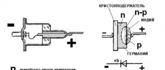
Figure 1. Planar diode: a. diode device, b. designation of a diode in electrical circuits, c. appearance of planar diodes of various powers.
The layer at the interface of p- and n-type semiconductors (pn junction) has one-way conductivity? conducts current well in one (forward) direction and very poorly in the opposite (reverse) direction. The structure of a planar diode is shown in Figure 1a. The basis ? a semiconductor plate (germanium) with a small amount of donor impurity (n-type), on which a piece of indium, which is an acceptor impurity, is placed.
Once heated, indium diffuses into the adjacent regions of the semiconductor, converting them into a p-type semiconductor. A pn junction occurs at the boundary of regions with two types of conductivity. The terminal connected to the p-type semiconductor is called the anode of the resulting diode, the opposite? its cathode. An image of a semiconductor diode on circuit diagrams is shown in Fig. 1b, appearance of planar diodes of various powers? in Fig. 1st century
You can't do without chargers
To perform this operation, as already noted, chargers operating from a 220 V network are used. There are a lot of such devices on the automotive market, they may have various useful additional functions.
However, they all do the same job - convert alternating voltage 220 V into direct voltage - 13.8-14.4 V.
In some models, the charging current is manually adjusted, but there are also models with fully automatic operation.
Of all the disadvantages of purchased chargers, one can note their high cost, and the more sophisticated the device, the higher the price.
But many people have a large number of electrical appliances at hand, the components of which may well be suitable for creating a homemade charger.
Yes, a homemade device will not look as presentable as a purchased one, but its task is to charge the battery, and not to “show off” on the shelf.
One of the most important conditions when creating a charger is at least basic knowledge of electrical engineering and radio electronics, as well as the ability to hold a soldering iron in your hands and be able to use it correctly.
Next, we will consider several battery charger circuits that can be created from old electrical appliances or electronic components.
The simplest rectifier
Figure 2. Current characteristics in various circuits.
The current flowing in a conventional lighting network is variable. Its magnitude and direction change 50 times within one second. A graph of its voltage versus time is shown in Fig. 2a. Positive half-cycles are shown in red, ? negative.
Since the current value varies from zero to the maximum (amplitude) value, the concept of the effective value of current and voltage is introduced. For example, in a lighting network the effective voltage value is 220 V? in a heating device connected to this network, the same amount of heat is generated over equal periods of time as in the same device in a 220 V DC circuit.
But in fact, the network voltage changes in 0.02 s as follows:
- the first quarter of this time (period)? increases from 0 to 311 V,
- second quarter of the period? decreases from 311 V to 0,
- third quarter of the period? decreases from 0 to 311 V,
- last quarter of the period? increases from 311 V to 0.
In this case, 311 V? voltage amplitude Uо. The amplitude and effective (U) voltages are related to each other by the formula:
When a series-connected diode (VD) and load are connected to an alternating current circuit (Fig. 2b), current flows through it only during positive half-cycles (Fig. 2c). This happens due to the one-way conductivity of the diode. Is such a rectifier called half-wave? During one half of the period there is current in the circuit, during the second? absent.
The current flowing through the load in such a rectifier is not constant, but pulsating. You can turn it almost constant by connecting a filter capacitor Cf of a sufficiently large capacity in parallel with the load. During the first quarter of the period, the capacitor is charged to the amplitude value, and in the intervals between pulsations it is discharged to the load. The tension becomes almost constant. The greater the capacitor capacity, the stronger the smoothing effect.
Direct and alternating current
From the physics course, everyone knows that electric current involves the flow of electric charge from one conductor to another. Unlike direct current, which actually flows in one direction (from negative to positive), alternating current flows first in one direction and then in the other. If you connect an oscilloscope to a power outlet, you can get a schematic representation of such current movement.
The figure shows an alternating current oscillogram, where the x-axis shows time and the y-axis shows voltage. The graph clearly shows that the voltage smoothly increases to a value of 220 V, then decreases to zero and increases to the same value, but with the opposite sign. In other words, the voltage in the outlet constantly changes sign at a rate of 50 times per second.
The DC waveform shown in the image clearly demonstrates how the terminal voltage remains constant throughout the entire time. When the circuit is closed, the current will flow in one direction.
Diode bridge circuit
More advanced is the full-wave rectification circuit, when both positive and negative half-cycles are used. There are several varieties of such schemes, but the most commonly used is pavement. The diode bridge circuit is shown in Fig. 3c. The red line on it shows how current flows through the load during positive times, and the blue line? negative half-cycles.
Figure 4. 12 volt rectifier circuit using a diode bridge.
In both the first and second half of the period, the current through the load flows in the same direction (Fig. 3b). The amount of pulsation within one second is not 50, as with half-wave rectification, but 100. Accordingly, with the same filter capacitor capacity, the smoothing effect will be more pronounced.
As you can see, to build a diode bridge you need 4 diodes? VD1-VD4. Previously, diode bridges on circuit diagrams were depicted exactly as in Fig. 3c. The image shown in Fig. 1 is now generally accepted. 3g. Although there is only one picture of a diode, it should not be forgotten that the bridge consists of four diodes.
The bridge circuit is most often assembled from individual diodes, but sometimes monolithic diode assemblies are also used. They are easier to mount on the board, but if one arm of the bridge fails, the entire assembly is replaced. The diodes from which the bridge is mounted are selected based on the amount of current flowing through them and the amount of permissible reverse voltage. This data can be obtained from diode instructions or reference books.
The complete circuit of a 12 volt rectifier using a diode bridge is shown in Fig. 4. T1? step-down transformer, the secondary winding of which provides a voltage of 10-12 V. Fuse FU1? This is a useful detail from a safety point of view and should not be neglected. The brand of diodes VD1-VD4, as already mentioned, is determined by the amount of current that will be consumed from the rectifier. Capacitor C1? electrolytic, with a capacity of 1000.0 μF or higher for a voltage of at least 16 V.
Output voltage? fixed, its value depends on the load. The higher the current, the lower the voltage. To obtain a regulated and stable output voltage, a more complex circuit is required. Obtain the regulated voltage from the circuit shown in Fig. 4 can be done in two ways:
It is hoped that the descriptions and diagrams given above will provide practical assistance in assembling a simple rectifier for practical needs.
There is an inconsistency in electrical engineering. On the one hand, it is more convenient to transmit energy over long distances if it is in the form of alternating voltage. On the other hand, direct current is required to power smartphones, LEDs in light bulbs, circuit boards in TVs and similar household appliances. This problem is successfully solved by a family of radio components such as rectifier diodes.
Design and principle of operation
A diode bridge is an electronic circuit assembled on the basis of rectifier diodes, which is designed to convert the alternating current supplied to it into direct current. Most often, Schottky diodes are included in the circuit, but this is not a categorical requirement, therefore, in any particular case, it can be replaced by other models that are suitable in terms of technical parameters. The semiconductor diode bridge circuit includes four elements for one phase. The diode bridge can be assembled either with individual diodes or assembled as a single unit, in the form of a monolithic four-terminal network.
The operating principle of a diode bridge is based on the ability of a p–n junction to pass electric current in only one direction. The circuit for connecting diodes to the bridge is designed in such a way that each half-wave creates its own path for the flow of electric current to the connected load.
Rice. 1. Operating principle of the diode bridge
To explain diode bridge rectification, it is necessary to consider the operation of the circuit relative to the shape of the input voltage. It should be noted that the voltage curve for one period has two half-waves - positive and negative. In turn, each half-wave has a process of increasing and decreasing relative to the maximum amplitude point.
Therefore, the operation of the rectifier device will have the following stages:
- An alternating voltage of 220V is supplied to the input of the rectifier bridge, designated by the letters A and B.
- Each half-wave supplied from the electrical network or from the windings of a transformer is converted into a constant value by a pair of diodes located diagonally.
- The positive half-wave will be conducted by a pair of diodes VD1 and VD4 and output a half-wave in the positive region of the ordinate axis to the bridge output.
- The negative half-wave will be rectified by a pair of diodes VD2 and VD3, from which another half-wave will appear in the positive region at the same bridge output.
Due to the fact that both half-cycles are realized at the output of the diode bridge, such an electronic device is called a full-wave rectifier, also called a Graetz circuit.
Designation on the diagram and markings
On the electrical circuit, the diode bridge can have different image options. Most often you can find the following designations:
Rice. 2. Designation on the diagram
The first option for designating a bridge rectifier is used, as a rule, in situations where the electronic device is a monolithic structure, a single assembly. In the diagram, marking is done in Latin letters VD, followed by a serial number.
The second option is most common for situations where the diode bridge consists of individual semiconductor devices assembled into one circuit. The marking of the second option is most often carried out in the form of a series VD1 - VD4.
It should also be noted that the above schematic designation and marking, although of a generally accepted nature, may be violated when drawing up diagrams.
Types of diode bridges
Depending on the number of phases that are connected to the diode bridge, single-phase and three-phase models are distinguished. We examined the first option in detail using the example of the Graetz scheme above.
Three-phase rectifiers, in turn, are divided into six- and twelve-pulse models, although their diode bridge circuit is identical. Let us consider in more detail the operation of a diode device for a three-phase circuit.
Rice. 3. Three-phase diode bridge circuit
The diode bridge shown in the figure above is called the Larionov circuit. Structurally, for each phase, two diodes are installed at once in the opposite direction relative to each other
It is important to note here that the sinusoid in all three phases has a shift of 120° relative to each other, therefore, at the outputs of the device, when the resulting diagram is superimposed, the following picture will appear:
Rice. 4. Voltage rectified by a three-phase bridge
As you can see, in comparison with a single-phase rectifier based on a diode bridge, the picture turns out to be smoother, and voltage surges have a significantly smaller amplitude.
What are diodes
A diode is a semiconductor element based on a silicon crystal. Previously, these parts were also made of germanium, but over time this material was forced out due to its shortcomings. The electrical diode functions as a valve, i.e. it allows current to flow in one direction and blocks it in the other. Such capabilities are built into this part at the level of the atomic structure of its semiconductor crystals.
Read also: How to prepare a hide for duck hunting with your own hands
One diode cannot obtain a full constant voltage from an alternating voltage. Therefore, in practice, more complex combinations of these elements are used. An assembly of 4 or 6 parts, combined according to a special circuit, forms a diode bridge. He is already quite capable of coping with full current rectification.
Interesting. Diodes have parasitic sensitivity to temperature and light. Transparent rectifiers in a glass case can be used as light sensors. Germanium diodes (approx. D9B) are suitable as a temperature-sensitive element. Actually, due to the strong dependence of the properties of these elements on temperature, they stopped producing them.
Principle of operation
It is not difficult to understand the principle of operation of a semiconductor diode. All you need is to understand the basic laws of physics and know how some electrical processes occur.
Initially, an electric current acts on the cathode, which causes the heating element to glow. In turn, electrons are emitted from the electrode, and an electric field appears between the two parts.
The formation of a spatially negative charge begins in the two electrodes, which can impede the flow of electrons. However, this only happens when the anode potential decreases, as a result of which the mass of electrons is not able to cope with the negative elements, which forces them to move in the reverse order, that is, the electrons return to the cathode again.
Often the cathode current readings remain zero - this happens when exposed to particles with a minus charge. As a result, the generated field does not force the electrons to move faster, but causes the opposite reaction - it slows them down and forces them to return back to the cathode. Eventually the circuit opens as the diode remains in the off state.
Single-phase and three-phase diode bridge
There are two main types of straightening assemblies:
- Single-phase bridge. Most often used in household electrical appliances. Has 4 outputs. Two of them are supplied with alternating voltage, i.e. phase (L) and zero (N). The permanent one is removed from the remaining two, i.e. plus (+) and minus (-).
- Three-phase bridge. It is found in powerful industrial installations and equipment powered by a 380 volt network. Three phases are supplied to its input (L1, L2, L3). The constant voltage is also removed from the output. Such bridges are distinguished by their large size and impressive currents that they are capable of passing through themselves.
Purpose and practical use
The scope of use of a bridge made of diodes is quite wide. These can be power supplies and control units. It is installed in all devices powered by a 220 volt industrial network. For example, TVs, receivers, chargers, dishwashers, LED lamps. Cars cannot do without it either. After starting the engine, the generator starts working, producing alternating current. Since the on-board network is all powered by constant voltage, a rectifier bridge is installed through which rectified voltage is supplied. The same constant signal also recharges the battery.
The rectifier device is used to operate the welding machine. True, it uses powerful devices that can withstand currents of more than 200 amperes. The use of diode assembly in devices provides a number of advantages compared to a simple diode. This straightening allows you to:
- increase the ripple frequency, which can then simply be smoothed out using an electrolytic capacitor;
- when working together with a transformer, get rid of the bias current, which makes it possible to more efficiently use the overall power of the converter;
- pass more power with less heat, thereby increasing efficiency.
But it is also worth noting the drawback due to which in some cases the bridge is not used. First of all, this is a double voltage drop, which is especially sensitive in low-voltage circuits. And also, when some of the diodes burn out, the device begins to operate in half-wave mode, which is why parasitic harmonics penetrate into the circuit, which can damage sensitive radioelements.
power unit
Not a single modern power supply can do without a rectifier. High-quality sources are manufactured using bridge rectifiers. The classic scheme consists of only three parts:
- A step-down transformer.
- Rectifier bridge.
- Filter.
A sinusoidal signal with an amplitude of 220 volts is supplied to the primary winding of the transformer. Due to the phenomenon of electromagnetic induction, an electromotive force is induced in its secondary winding and current begins to flow. Depending on the type of transformer, the voltage value is reduced by a certain value due to the transformation ratio. An alternating signal with reduced amplitude appears between the terminals of the secondary winding. In accordance with the diode bridge connection diagram, this voltage is supplied to its input. Passing through the diode assembly, the alternating signal is converted into a pulsating one.
This form is often considered unacceptable, for example, for sound equipment or lighting sources. Therefore, a capacitor connected in parallel with the output of the rectifier is used for smoothing.
Three-phase rectifier
In production and in places where a three-phase network is used, a three-phase rectifier is used. It consists of six diodes, one pair for each phase. Using this type of device allows you to obtain a higher current value with low ripple. This, in turn, reduces the requirements for the output filter. The most popular options for connecting three-phase rectifiers are the Mitkevich and Larionov circuits. In this case, not only six diodes can be used simultaneously, but also 12 or even 24. Three-phase bridges are used in diesel locomotives, electric vehicles, on drilling rigs, and in industrial gas and water purification plants.
A generator diode bridge is present exclusively in “on-board power plants” of alternating current. Since most passenger cars are equipped with alternating current generators, a rectifier with diodes and a zener diode is present in each of them. Usually this unit is built into the generator, but there are remote diode bridges for convenient service, repair and replacement of diodes.
Operating principle of a diode bridge
You can understand how a bridge performs its task by understanding how a separate diode behaves. Initially there are only two wires with alternating voltage (L and N). It has the shape of a sinusoid (Fig. a). If you add one diode to the circuit, then it will transmit only the positive half-wave (Fig. b), if this component is deployed, then the negative component (Fig. c). This voltage will no longer be variable. However, it is not suitable for powering serious electrical appliances. There are moments in it when there is no current at all. The use of four diodes will allow you to obtain a constant voltage without any interruptions (Fig. d). Three-phase bridges are straightened using the same method. However, they do this with three sine waves at the same time.
How to calculate and select a diode bridge based on power
The maximum ripple voltage present in the full-wave rectifier circuit is determined not only by the value of the smoothing capacitor, but also by the frequency and load current and is calculated as:
Rectifier Bridge Ripple Voltage
Ripple Voltage Formula
Where: I is the DC load current in amperes, ƒ is the ripple frequency or twice the input frequency in Hertz, and C is the capacitance in Farads.
The main advantages of a full-wave bridge rectifier are that it has lower AC ripple for a given load and a smaller reservoir or smoothing capacitor than an equivalent half-wave rectifier. Therefore, the fundamental frequency of the ripple voltage is twice the AC frequency (100 Hz), where for a half-wave rectifier it is exactly equal to the supply frequency (50 Hz).
The amount of ripple voltage that is superimposed on top of the DC supply voltage by the diodes can be virtually eliminated by adding a greatly improved π filter (pi filter) to the output terminals of the bridge rectifier. This type of low-pass filter consists of two smoothing capacitors, usually of the same value, and an inductor or inductor across them to introduce a high-impedance path into the variable ripple component.
Bridge rectifier
Another, more practical and cheaper alternative is to use an off-the-shelf three-pole voltage regulator IC such as the LM78xx (where xx denotes the rated output voltage) for positive output voltage, or its inverse equivalent, LM79xx for negative output voltage, which can reduce ripple by more than 70 dB (datasheet), providing a continuous output current of more than 1 amp.
Many circuits with this technology are built with a bridge rectifier. Bridge rectifiers convert AC to DC using their diode system made of semiconductor material, either in a half-wave method, which rectifies one direction of the AC signal, or in a full-wave method, which rectifies both directions of the AC input signal.
Diode bridge GBL10
Semiconductors are materials that allow current to pass because they are made of metals such as gallium or metalloids such as silicon that are contaminated with materials such as phosphorus as a means of controlling the current. You can use a bridge rectifier for a variety of applications for a wide range of currents.
Bridge rectifiers also have the advantage of delivering more voltage and power than other rectifiers. Despite these advantages, bridge rectifiers suffer from the need to use four diodes with additional diodes compared to other rectifiers, causing a voltage drop that reduces the output voltage.
Rectifier
The voltage obtained after the diode bridge has the shape of a sinusoid, in which the negative component is reflected relative to the time axis. In simple terms, it is shaped like hills and is called pulsating. This voltage is positive. Does not contain moments when current does not flow. But it is still unstable. For example, at point “a” it is early 0 volts, and at “b” it has a maximum value. This rectifier cannot be considered complete.
To solve this problem, a smoothing electrolytic capacitor is required. On the board it is usually located in the same place as the diode assembly. The capacitance accumulates energy at those moments when it has peak values (point b), and releases it at moments of dips (a). The output is a straight line - full-fledged direct current, suitable for powering subsequent electronic components, processors, microcircuits, etc.
Schematic diagram
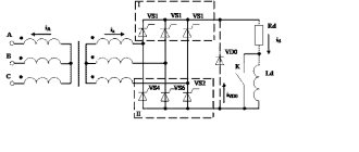
The starting charger circuit contains a triac voltage regulator (VS1), a power transformer (T1), a rectifier with powerful diodes (VD3, VD4) and a starter battery (GB1). The charging current is selected by the current regulator on the triac VS1, its current is regulated by the variable resistor R2 and depends on the battery capacity.
The input and output charging circuits have filter capacitors, which reduce the degree of radio interference during operation of the triac regulator. Triac VS1 provides regulation of the charging current when the network voltage varies from 180 to 220 V.
The triac wiring consists of R1-R2-C3 (RC circuit), dinistor VD2 and diode bridge VD1. The time constant of the RC circuit affects the opening moment of the dinistor (counting from the beginning of the network half-cycle), which is included in the diagonal of the rectifier bridge through the limiting resistor R4. The rectifier bridge synchronizes the switching on of the triac in both half-cycles of the mains voltage. In the “Regeneration” mode, only one half-cycle of the mains voltage is applied, which helps clean the battery plates from existing crystallization. Capacitors C1 and C2 reduce the degree of interference from the triac in the network to acceptable levels.
Disadvantages of a full bridge
A full-fledged full-wave bridge has disadvantages:
- The current is forced to flow not through one diode, but through two at once, connected in series. Therefore, the voltage drop across the rectifier element doubles. For low-power bridges on silicon diodes it can reach 2 volts. In powerful rectifiers - about 10 V. Hence, significant power losses on the rectifying element and its increased heating.
- If one or four diodes fail, the bridge continues to operate. This defect may not be noticeable without special measurements. However, it creates the risk of more serious damage to the device, which is powered through a faulty bridge.
Settings
When setting up, the internal battery GB1 is connected to the device (observe the polarity!), and the regulation of the charging current by resistor R2 is tested. Then the charging current is checked in charge, start and regeneration modes. If the current is no more than 10...12A, then the control unit is in working condition. When connecting the charging and starting device to the car battery, the charge current should initially increase approximately 2-3 times, and after 10 - 30 minutes it should drop to its original value. After this, switch SA3 is clicked into the “Start” mode, and the car engine starts. In case of an unsuccessful attempt to start the engine, additional recharging is performed for 10 - 30 minutes, and the attempt is repeated.
Design
The circuit of any rectifier bridge includes diodes. They can be separately soldered onto a printed circuit board or located in the same housing. Regarding the size, rectifiers are miniature, for example, imported MB6S or Soviet KTs405A. The latter are popularly called “ka-tseshki” or “chocolates”.
There are samples with impressive dimensions. For example, a three-phase rectifier bridge made in China. The device is designed for currents of hundreds of amperes, therefore it has screw fastening for power wires and a flat metal heat-conducting surface with holes for fixing on the cooling radiator.
Main characteristics
Both individual diodes and industrial diode assemblies are described by a standard set of technical characteristics:
PHOTO: go-radio.ru Variant of the bridge image on the electrical circuit diagram
PHOTO: go-radio.ru Assembly of the “Diode Bridge” on a printed circuit board
Rectifier markings
There are no generally accepted rules according to which manufacturers label their diode bridges. Everyone has the right to name their product as they see fit, i.e. according to its own nomenclature.
However, most of these parts have similar features that help visually determine the purpose of their pins. In the photo of a three-phase bridge (see above), the alternating current symbol is highlighted separately - a wavy line. It indicates that a sinusoidal input voltage is connected to this pin. Also on some bridge models, the input terminals are marked with the letters AC (Alternative Current), indicating alternating current. In this case, the output contacts from which direct current is removed are indicated by the symbols DC (Direct Current) or the traditional “+” and “-”. Additionally, on some rectifiers, one of the corners is “filed” on the plus side. An extended pin can also indicate “+”. This type of marking is common to many electronic components and is called a key.
Three-phase bridge
Now that you know what a diode bridge is for and what it is, let's look at a more complex three-phase circuit that produces pulsating current. It is as close to constant as possible and is suitable for use in devices that require a stable supply. The input of this system is connected to a source that supplies three-phase power (of course we are talking about alternating current). This could be a transformer or a generator. The output of the system is an almost ideal direct current, which can be easily smoothed out.
Rectifier circuit
To make a high-quality full-wave rectifier from the connection diagram of a diode bridge with a capacitor, study our drawing. In this case, the current is rectified, which is removed from the step-down transformer winding. Equalization occurs due to an electrolytic capacitor of 5-10 thousand microfarads, which charges and releases the charge into the network. An additional resistor is also introduced into the circuit, which rectifies the current during idle operation. The higher the load, the lower the output voltage, so a stabilizer using classic transistors is connected to it.
Using our diagrams, you can easily figure out how to make a diode bridge and how to use it. We recommend purchasing ready-made devices to save space and not have to select values.
DIY diode bridge
To assemble the rectifier yourself, you will need 4 diodes of the same type. At the same time, they must be suitable in terms of reverse voltage, maximum current and operating frequency. Connections must be made in accordance with the diagram below. A positive voltage is removed between the two cathodes and a negative voltage between the anodes. An alternating voltage source is connected to the points at which opposite terminals of the diodes are connected. The entire circuit can be soldered by surface mounting in a couple of minutes, or you can work hard and make it in the form of a small printed circuit board.
Additional Information. The reverse voltages of diodes connected in a series circuit are added to each other.
Memory circuit for Rassvet 2
Look in the picture at the diagram of the Rassvet 2 charger. It is compiled according to the original charger. If you master this scheme, you will be able to independently create a high-quality copy that is no different from the original sample. Structurally, the device is a separate unit, closed with a housing to protect the electronics from moisture and exposure to bad weather conditions. It is necessary to connect a transformer and thyristors on the radiators to the base of the case. You will need a board that will stabilize the current charge and control the thyristors and terminals.
Selecting a build type
For each task there is its own optimal version of the rectifier diode assembly. All of them can be divided into 3 types:
- Rectifier with one diode. It is used in the simplest and cheapest circuits where there is no c.l. requirements for the quality of the output voltage, as, for example, in night lights.
- Dual diode. These parts look similar to transistors, because they are produced in the same packages. They also have 3 pins. Essentially, these are two diodes placed in one housing. One of the conclusions is average. It can be the common cathode or the anode of the internal diodes.
- Full diode bridge. 4 parts in one case. Suitable for devices with high currents. It is mainly used on the inputs and outputs of various power supplies and chargers.
Additional Information. Rectifiers are also used in cars. They are needed to convert the alternating voltage coming from the generator to direct voltage. This, in turn, is necessary to charge the battery. A conventional gas generator produces alternating current.
Read also: How to make a cardboard car with your own hands
Scope and purpose
Most often, diode bridges are used in power supplies. In transformer power supplies they are connected to the secondary winding of the transformer
In pulse power supplies - to the 220V network input. In this case, the electronic control circuit and the power circuit of the UPS are powered by a rectified and smoothed (not always) mains voltage (reaches about 300-310 Volts).
There is high-frequency alternating voltage at the terminals of the secondary winding of the switching power supply. In order to straighten it, assemblies of dual Schottky diodes are installed. In this regard, a midpoint rectification scheme is often used.
In cars and motorcycles, three-phase diode bridges are used, assembled according to the Larionov circuit with three additional valves, because a three-phase generator is used to power the on-board network. The bridge in the generator is made in the form of a sector of a circle and is installed on its rear part.
An exception is some modern cars from Toyota and other brands; they use a 6-phase generator to implement a twelve-pulse rectification circuit of 12 valves. This is necessary to reduce ripple and increase output current.
Checking elements
In most cases, it is not necessary to unsolder the bridge from the board for testing. It should be tested in the same way as a 4 pn junction with a diode bridge connection. This measurement is so common that its capability is implemented in any multimeter. The test device must be switched to diode continuity mode.
The forward voltage drop across a working rectifier diode is 500-700 mV. Otherwise, the device will display “1”. A burnt part most often shows “0” in both directions, i.e. short circuit. Less often, a complete breakage of the element occurs (also in both directions). All measurements should be repeated for each diode included in the bridge. Total 8 measurements, i.e. 4 in forward direction and 4 in reverse. If a Schottky diode is tested, then this parameter is 200-400 mV.
Instructions for verification
In answer to the question of how to check a diode with a multimeter without desoldering, it is necessary to clarify that in order to successfully test it, like a zener diode, you need to take it and a multimeter and make a test. As a rule, many of the devices are equipped with a diode test function. According to the instructions, it looks like this:
Anode and cathode
- All you need to do is set the regulator to the test function, take the ends of the multimeter and connect them to the diode assembly. You need to bring the anode to the minus sign, and the cathode to the plus sign. Often these are simply white and red stripes, respectively.
- Then the threshold voltage values and the value from the test readings will appear.
Connecting the anode and cathode
Note! When checking a Schottky or Schottky rectifier LED, you cannot touch one of the charges with your hands, since the readings in this case will not be correct. During the first determination, you need to repeat the procedure in the opposite order
So, the anode must be placed to the plus sign, and the cathode to the minus sign. With this connection, the multimeter will receive the number 1. This means that no current is flowing. Everything is protected.
It is worth noting that more detailed instructions with diagrams, answers to popular questions about LED narrow suppressors and warnings are given in the instructions for each multimeter.
Multimeter for checking the diode assembly
Checking the serviceability of semiconductor elements
To check semiconductor elements for serviceability, you need to use a digital measuring multimeter with a lid and great functionality. Most of them are equipped with a similar function for ringing the bridge and generator, so anyone can do the verification procedure. All you need to do is ring the free diode using a multifunctional multimeter, install the control knob on the measuring device and press the button with this designation on the control panel. Next, you need to connect the corresponding red probe to the anode, and the black one to the cathode. This is the only way the device will measure everything correctly.
Note! It is easy to understand where the anode is and where the cathode is by reading the description of the multimeter model, or using the help of an electronics engineer. As a rule, each wiring has its own marking, thanks to which it is very easy to understand where everything is in a particular situation.
The result should be a threshold forward voltage. If there is damage to any element, then a zero will appear on the panel opposite the electrode that will be connected, or a number higher or lower than the permissible one.
In response to how to check a diode assembly with a multimeter, if there is no special mode in the multimeter, you can indicate that it is necessary to assemble a circuit: connect the power source to a resistor and the semiconductor being tested. Then connect the anode element to the resistor, and the cathode to the power source. Next, you should press start and see what state the semiconductor element is in. As in the previous case, a working element will produce a direct voltage with the meter.
Checking with a multimeter without soldering
Without desoldering, you can check the electrodes with a multimeter. All you need to do is select the resistive measuring mode on the device with a range of 2 kOhm. Then, as standard, you need to connect the red wire to the anode part, and the black wire to the cathode part. This will show the voltage in ohms. As a rule, when the circuit is broken, the measurement is obtained with a figure higher than the permissible value or with a value of 0.
Note! It is important to understand that in order to test equipment and semiconductor elements, you must fully act in accordance with the instructions provided with the multimeter. It is also necessary to understand important physics and understand a little electronics to draw up a proper electrical diagram. Otherwise, lack of knowledge may make it difficult to operate the multimeter
Otherwise, lack of knowledge may make it difficult to operate the multimeter.
Correct connection of the electrodes is the key to a successful test
Using the Schottky barrier
The use of a Schottky diode is justified in two cases. Firstly, when you need to rectify high-frequency current. The Schottky barrier is ideal for such a task, because it has a low junction capacitance and, accordingly, is fast-acting. Secondly, when it is necessary to rectify a large current of tens or hundreds of amperes. In this case, the part performs well due to the low voltage drop and low heat generation.
Diode bridges in the world of electronics play the role of a matching element. With their help, you can connect devices that require direct current to a network of alternating voltage convenient for transmission. There are a lot of such devices in everyday life; they are extremely important for a person’s comfortable life.
The main element used to create a rectifier unit is a diode. Its operation is based on the electron-hole transition (pn).
The generally accepted definition says: a pn junction is a region of space located at the boundary of the junction of two semiconductors of different types. In this space, an n-type to p-type transition is formed. The value of conductivity depends on the atomic structure of the material, namely on how tightly the atoms hold electrons. Atoms in semiconductors are arranged in a lattice, and electrons are bound to them by electrochemical forces. This material itself is a dielectric. It either conducts current poorly or does not conduct it at all. But if atoms of certain elements are added to the lattice (doping), the physical properties of such a material change radically.
Mixed atoms begin to form, depending on their nature, free electrons or holes. The resulting excess electrons form a negative charge, and the holes form a positive charge.
An excess charge of one sign causes carriers to repel each other, while an area with an opposite charge tends to attract them towards itself. An electron, moving, occupies a free space, a hole. At the same time, a hole also forms in its old place. As a result, two flows of charge movement are created: one main and the other reverse. A material with a negative charge uses electrons as majority carriers and is called an n-type semiconductor, while a material with a positive charge using holes is called a p-type semiconductor. In both types of semiconductors, minority charges generate a current opposite to the movement of the main charges.
In radio electronics, germanium and silicon are used from materials to create pn junctions. When crystals of these substances are doped, a semiconductor with different conductivity is formed. For example, the introduction of boron leads to the appearance of free holes and the formation of p-type conductivity. Adding phosphorus, on the other hand, will create electrons and the semiconductor will become n-type.
Scheme of a 100% working 12 volt charger
Look in the picture at the diagram of a 12 V charger. The equipment is intended for charging car batteries with a voltage of 14.5 Volts. The maximum current received during charging is 6 A. But the device is also suitable for other batteries - lithium-ion, since the voltage and output current can be adjusted. All the main components for assembling the device can be found on the Aliexpress website.
- dc-dc buck converter.
- Ammeter.
- Diode bridge KVRS 5010.
- Hubs 2200 uF at 50 volts.
- transformer TS 180-2.
- Circuit breakers.
- Plug for connecting to the network.
- "Crocodiles" for connecting terminals.
- Radiator for diode bridge.
Any transformer can be used at your own discretion. The main thing is that its power is not lower than 150 W (with a charging current of 6 A). It is necessary to install thick and short wires on the equipment. The diode bridge is fixed on a large radiator.
Diode operating principle
A diode is a semiconductor device that has low resistance to current in one direction and prevents it from flowing in the opposite direction. Physically, the diode consists of one pn junction. Structurally, it is an element containing two outputs. The terminal connected to the p-region is called the anode, and the terminal connected to the n-region is called the cathode.
When a diode operates, there are three states:
A forward potential is a signal when the positive pole of the power source is connected to the p-type region of the semiconductor, in other words, the polarity of the external voltage coincides with the polarity of the main carriers. With reverse potential, the negative pole is connected to the p-region and the positive pole to the n region.
There is a potential barrier in the area where the n- and p-type material joins. It is formed by a contact potential difference and is in a balanced state. The height of the barrier does not exceed tenths of a volt and prevents the movement of charge carriers deep into the material.
If direct voltage is connected to the device, then the magnitude of the potential barrier decreases and it practically does not resist the flow of current. Its value increases and depends only on the resistance of the p- and n-regions. When a reverse potential is applied, the barrier value increases, since electrons leave the n-region and holes leave the p-region. The layers become depleted and the barrier's resistance to the passage of current increases.
The main indicator of an element is the current-voltage characteristic. It shows the relationship between the potential applied to it and the current flowing through it. This characteristic is presented in the form of a graph, which indicates the forward and reverse current.
Basic diode faults
Sometimes devices of this type fail, this may occur due to natural depreciation and aging of these elements or for other reasons.
In total, there are 3 main types of common faults:
- Breakdown of the junction leads to the fact that the diode, instead of a semiconductor device, becomes essentially a very ordinary conductor. In this state, it loses its basic properties and begins to pass electric current in absolutely any direction. Such a breakdown is easily detected using a standard multimeter, which starts beeping and shows a low resistance level in the diode.
- When a break occurs, the reverse process occurs - the device generally stops passing electric current in any direction, that is, it essentially becomes an insulator. To accurately determine a break, it is necessary to use testers with high-quality and serviceable probes, otherwise they can sometimes falsely diagnose this malfunction. In alloy semiconductor varieties, such a breakdown is extremely rare.
- A leak during which the seal of the device body is broken, as a result of which it cannot function properly.
Breakdown of pn junction
Such breakdowns occur in situations where the reverse electric current begins to suddenly and sharply increase, this happens due to the fact that the voltage of the corresponding type reaches unacceptable high values.
There are usually several types:
- Thermal breakdowns, which are caused by a sharp increase in temperature and subsequent overheating.
- Electrical breakdowns that occur under the influence of current on the junction.
The graph of the current-voltage characteristic allows you to visually study these processes and the difference between them.
Electrical breakdown
The consequences caused by electrical breakdowns are not irreversible, since they do not destroy the crystal itself. Therefore, with a gradual decrease in voltage, it is possible to restore all the properties and operating parameters of the diode.
At the same time, breakdowns of this type are divided into two types:
- Tunneling breakdowns occur when high voltage passes through narrow junctions, which allows individual electrons to escape through it. They usually occur if semiconductor molecules contain a large number of different impurities. During such a breakdown, the reverse current begins to increase sharply and rapidly, and the corresponding voltage is at a low level.
- Avalanche types of breakdowns are possible due to the influence of strong fields that can accelerate charge carriers to the maximum level, due to which they knock out a number of valence electrons from atoms, which then fly into the conductive region. This phenomenon is avalanche-like in nature, which is why this type of breakdown received its name.
Thermal breakdown
The occurrence of such a breakdown can occur for two main reasons: insufficient heat removal and overheating of the pn junction, which occurs due to the flow of electric current through it at too high rates.
An increase in temperature in the transition and neighboring areas causes the following consequences:
- The growth of vibrations of the atoms that make up the crystal.
- Electrons entering the conductive band.
- A sharp increase in temperature.
- Destruction and deformation of the crystal structure.
- Complete failure and breakdown of the entire radio component.
It’s also important to know: 3 nuances about operation
The homemade product differs somewhat in its method of operation from the factory version. This is explained by the fact that the purchased unit has built-in functions that help with operation. They are difficult to install on a device assembled at home, and therefore you will have to adhere to several rules during operation.
- A self-assembled charger will not turn off when the battery is fully charged. That is why it is necessary to periodically monitor the equipment and connect a multimeter to it to monitor the charge.
- You need to be very careful not to confuse “plus” and “minus”, otherwise the charger will burn out.
- The equipment must be turned off when connecting to the charger.
By following these simple rules, you will be able to properly recharge the battery and avoid unpleasant consequences.
How to charge the battery
Wipe the battery with a cloth soaked in soda solution, then dry. Remove the plugs and check the electrolyte level; if necessary, add distilled water. The plugs must be turned out during charging. No debris or dirt should get inside the battery. The room in which the battery is charged must be well ventilated.
Connect the battery to the charger and plug in the device. During charging, the voltage will gradually increase to 14.5 volts, the current will decrease over time. The battery can be conditionally considered charged when the charging current drops to 0.6 - 0.7 A.
Device diagram
All motorists have found themselves in such an unpleasant situation. There are two options: start the car with a charged battery from a neighbor’s car (if the neighbor doesn’t mind), in the jargon of car enthusiasts this sounds like “lighting a cigarette.” Well, the second way out is to charge the battery.
Simple rectifier circuit
Sinusoidal voltage is a periodic signal that varies over time. From a mathematical point of view, it is described by a function in which the origin corresponds to time equal to zero. The signal consists of two half-waves. The half-wave located in the upper part of the coordinates relative to zero is called a positive half-cycle, and in the lower part - negative.
When an alternating voltage is applied to the diode through a load connected to its terminals, current begins to flow. This current is due to the fact that at the moment the positive half-cycle of the input signal arrives, the diode opens. In this case, a positive potential is applied to the anode and a negative potential to the cathode. When the wave changes to a negative half-cycle, the diode is turned off, as the polarity of the signal at its terminals changes.
Thus, it turns out that the diode, as it were, cuts off the negative half-wave, without passing it to the load, and a pulsating current of only one polarity appears on it. Depending on the frequency of the applied voltage, and for industrial networks it is 50 Hz, the distance between the pulses also changes. This type of current is called rectified, and the process itself is called half-wave rectification.
Read also: Features of botanical bas-relief
By rectifying the signal using a single diode, you can power a load that does not have special requirements for voltage quality. For example, a filament. But if you power up, for example, a receiver, a low-frequency hum will appear, the source of which will be the gap that occurs between the pulses. To some extent, to get rid of the disadvantages of half-wave rectification, a capacitor connected in parallel with the load is used together with a diode. This capacitor will charge when pulses arrive and discharge when there are no pulses to the load. This means that the larger the capacitance value of the capacitor, the smoother the current across the load will be.
But the highest signal quality can be achieved if two half-waves are used simultaneously for rectification. The device that allows this to be realized is called a diode bridge, or in other words, a rectifier bridge.
Electricity rectification
Until the end of the 19th century, converting alternating voltage to direct voltage was a problem. With the invention of the diode - first vacuum, and later semiconductor - the situation changed radically. Thanks to its unique properties, the diode perfectly distinguishes polarity and makes it easy to sort currents in the desired direction. At first, separate diodes were used for these purposes, later diode bridges appeared, providing high quality rectification.
https://youtube.com/watch?v=XamfUIu4wDI
Single diode rectifier
A diode conducts current in only one direction, which is why it is called a semiconductor device. If you connect the plus of the voltage source to the cathode of the device, and the minus to the anode, the diode will behave like a regular conductor. If the polarity is changed, the device will close and turn into a dielectric. To answer the question of what this gives, you will have to assemble a simple circuit and again arm yourself with an oscilloscope.
The diagram shows the operation of a semiconductor diode in an alternating current circuit. The oscillogram on the left shows the picture at the output of the transformer - ordinary alternating current. After the diode, everything changes significantly - the negative half-wave of the alternating voltage disappears from the graph. The current has not yet become constant, but it is no longer alternating - there is no movement of the electric charge in the opposite direction. This type of current is usually called pulsating. They can't power electronics yet, but changes are evident. All that remains is to smooth out the pulse peaks. This is done using capacitors.
The diagram shows a half-wave rectifier with a smoothing capacitor. During a positive pulse, the voltage not only powers the load, but also charges the capacitor at the same time. When the pulse ends, the capacitor releases the accumulated energy, smoothing out voltage surges.
Full wave device
Despite the significant progress achieved in converting alternating current into direct current by previous experiments, the result is still far from ideal. The fact is that the frequency of alternating current is quite low (50 Hz), and hanging smoothing capacitors has its limitations. In order to significantly improve the shape of the output signal, you need to increase the frequency.
However, in sockets it is strictly fixed and does not depend on external factors. The negative half-wave of the voltage is cut off by a diode. Changing its polarity is not difficult at all - you just need to add a few diodes to assemble a bridge circuit. The figure shows a full-wave rectifier with four diodes, explaining how a diode bridge works:
When a positive half-wave appears, diodes VD2, VD3 will be turned on in the forward direction and will be open. VD1, VD2 - closed. The half-wave passes freely to the output of the rectifier. When the voltage changes polarity, the pairs of diodes will change places - VD1 and VD4 will open, VD2 and VD3 will close. The negative half-wave will also pass to the output, but will change polarity. The result will be the same pulsed unipolar voltage, but its frequency will double. All that remains is to add a smoothing capacitor and see what happens.
The full-wave rectifier with a smoothing capacitor in the image shows that the problem has been solved: the alternating voltage is converted to direct voltage. Of course, the consistency is not ideal - there are pulsations, but they can be dealt with using filters. In addition, any electronics allows for one or another amount of pulsation.
This circuit, consisting of four diodes, has become classic and is called a diode or rectifier bridge. There is a separate category of electronic devices - rectifier bridges. They consist of four diodes connected to each other in a suitable manner. As an example, you can look at the rectifier bridge KTS402G and its electrical circuit.
Setting the output voltage and charging current
There are two trimming resistors installed on the DC-DC converter board, one allows you to set the maximum output voltage, the other allows you to set the maximum charging current.
Plug in the charger (nothing is connected to the output wires), the indicator will show the voltage at the device output and the current is zero. Use the voltage potentiometer to set the output to 5 volts. Close the output wires together, use the current potentiometer to set the short circuit current to 6 A. Then eliminate the short circuit by disconnecting the output wires and use the voltage potentiometer to set the output to 14.5 volts.
Example with description
With little experience working with electrical circuits, it makes sense to start studying with simple circuits. You can come up with them yourself, gradually increasing functionality. For example, the classic circuit of an analog power supply with a stabilized output voltage:
- ~ 220 V - voltage supplied to the circuit in volts.
- 5...14 V is the potential difference that can be obtained at the output of the device.
- + - corresponds to the forward direction of current flow.
- — — denotes the return current path.
- T is a transformer with a grounded winding.
- S1 - 220 V switching button.
- VDS1 - diode bridge.
- KR142EN5A - stabilizing microcircuit.
- R2 - adjustable resistance.
- VT3, VT4 - output transistors.
All other elements play a secondary role, but are also important to ensure a stable output signal. As can be seen from the diagram, the supply voltage from an alternating network of 220 volts is supplied to the transformer through a 5 A fuse and the S1 button. The signal from it goes to a diode bridge assembled from four rectifiers. A constant voltage of the required value is generated at its output, while the parasitic alternating component is removed using capacitors C1 and C2.
Stabilizer VR1, according to the datasheet, produces a stable voltage amplitude equal to five volts at the output. In order for it to be changed, electrical feedback has been introduced. That is, its pin No. 8 is connected through a controlled resistor to the negative of the circuit (ground). This allows you to change the signal value at the output of the microcircuit by changing its resistance. Transistors connected to the output with their bases are nothing more than an emitter follower that allows you to increase the power of the power source.
To correctly perceive the circuit, it is important not only to understand the symbols, but also to understand the purpose of various electronic and radio elements. Then, without much difficulty, it will be possible to determine the type and shape of the signal at any point in the circuit diagram, which will help when repairing or improving an electrical device or circuit
Diode bridge
Such a device is an electrical device used to convert alternating current into direct current. The phrase “diode bridge” is formed from the word “diode”, which implies the use of diodes in it. The diode bridge rectifier circuit depends on the AC network to which it is connected. The network can be:
Depending on this, the rectifier bridge is called a Graetz bridge or a Larionov rectifier. In the first case, four diodes are used, and in the second, the device is assembled using six.
The first rectifier circuit was assembled using radio tubes and was considered a complex and expensive solution. But with the development of semiconductor technology, the diode bridge has completely replaced alternative methods of signal rectification. Selenium pillars are rarely used instead of diodes.
Device designs and characteristics
Structurally, the rectifier bridge is made of a set of individual diodes or a cast housing with four terminals. The body can be flat or cylindrical. According to the accepted standard, icons on the device body mark the terminals for connecting alternating voltage and the output constant signal. Rectifiers with a housing with a hole are designed for mounting on a radiator. The main characteristics of the rectifier bridge are:
- Highest forward voltage . This is the maximum value at which the device parameters do not go beyond the permissible limits.
- Highest permissible reverse voltage . This is the maximum pulse voltage at which the bridge operates for a long time and reliably.
- Maximum operating rectification current . Indicates the average current flowing through the bridge.
- Maximum frequency . The frequency of voltage supplied to the bridge at which the device operates efficiently and does not exceed the permissible heating.
Exceeding the rectifier's characteristics leads to a sharp reduction in its service life or breakdown of pn junctions. It should be noted that all diode parameters are indicated for an ambient temperature of 20 degrees. The disadvantages of using a bridge rectification circuit include a higher voltage drop compared to a half-wave circuit and a lower efficiency value. To reduce losses and reduce heating, bridges are often made using fast Schottky diodes.
Device connection diagram
On electrical circuits and printed circuit boards, a diode rectifier is indicated by a diode icon or in Latin letters. If the rectifier is assembled from individual diodes, then next to each is placed the designation VD and a number indicating the serial number of the diode in the circuit. VDS or BD labels are rarely used.
The diode rectifier can be connected directly to a 220 volt network or after a step-down transformer, but its connection circuit remains unchanged.
When a signal arrives in each half-cycle, current will only be able to flow through its own pair of diodes, and the opposite pair will be blocked for it. For a positive half-cycle, VD2 and VD3 will be open, and for a negative half-cycle, VD1 and VD4. As a result, the output will be a constant signal, but its pulsation frequency will be doubled. In order to reduce the ripple of the output signal, a parallel connection of capacitor C1 is used, as in the case of one diode. Such a capacitor is also called a smoothing capacitor.
But it happens that the diode bridge is placed not only in an alternating network, but is also connected to an already rectified one. Why a diode bridge is needed in such a circuit will become clear if you pay attention to which circuits use such a connection. These circuits involve the use of radioelements that are sensitive to power reversal. Using a bridge allows for simple but effective foolproof protection. In case of incorrect connection of the power polarity, the radio elements installed behind the bridge will not fail.
Functionality check
This type of electronic device can be checked without desoldering it from the circuit, since no shunting is used in the device designs. In the case of a rectifier assembled from diodes, each diode is checked separately. And in the case of a monolithic case, measurements are carried out on all four of its terminals.
The essence of the test comes down to checking the diodes for a short circuit with a multimeter. To do this, perform the following steps:
- The multimeter switches to diode or resistance vertebrae mode.
- The plug of one wire (black) is inserted into the common socket of the tester, and the second (red) into the resistance test socket.
- With the probe connected to the black wire, touch the first leg, and with the probe of the red wire, touch the third pin. The tester should show infinity, and if you change the polarity of the wires, the multimeter will show the transition resistance.
- The minus of the tester is fed to the fourth leg, and the plus to the third. The multimeter will show resistance; when changing polarity, infinity.
- Minus on the first leg, plus on the second. The tester will show an open transition, and when changing, a closed one.
Such tester readings indicate the serviceability of the rectifier. If you don't have a multimeter, you can use a regular voltmeter. But in this case you will have to supply power to the circuit and measure the voltage on the smoothing capacitor. Its value should exceed the input value by 1.4 times.
Popular posts
- DIY Easter egg for Easter 2022 - 5 best crafts 12 volt DC motor speed controller How to make a boat out of foam How to make welding pliers for spot welding How to build a horse stable Papercraft for beginners, paper modeling, 3D sculptures and simple paper figures for children How to make a bouquet in a box with your own hands: step-by-step instructions Drip irrigation in a greenhouse and in the garden with your own hands
Diode, bridges and current rectification difficulties
Initially, diodes were called vacuum tubes with two electrodes. The heated cathode emitted electrons that could fly in only one direction—to the anode. But no current flowed in the opposite direction. This made it possible to cut off part of the alternating voltage period. As a result, the current became rectified.
The design flaw is obvious - part of the time, half the interval, the circuit is inactive. For this reason, it is difficult to create high efficiency. We are not talking about efficiency, rather, we are talking about overall power. The voltage in the network is limited in nominal value; it is necessary to effectively use what is available. If you increase consumption through a single diode, it will overheat and burn out. This is where a diode bridge comes to the rescue.
Bridge design on the diagram
The designs discussed in the article are precisely aimed at improving certain properties. Otherwise, a diode bridge of a single configuration would have been used long ago. The well-known diode bridge with four valves is far from the only one for a simple reason - it is designed to work with one voltage phase. This is a defective option, supplied to our homes to save wires, and is not used in industry.
Let's start with Nikola Tesla. This man was the first to come up with a rotating magnetic field. Previously, alternating current was used, but with the help of a single phase the sounded phenomenon cannot be created. Inside the engine, the field needs to rotate. The only phase is physically unable to provide this. Nikola Tesla invented an asynchronous motor with many poles. Note that commutator types of motors can operate on alternating and direct current, but it is recommended to avoid designs with permanent magnets. The rotor and stator are assembled from copper windings. We believe that in the 19th century there were no such types of engines.
Let's go back to the phases. Having invented an asynchronous (induction) AC motor, Nikola Tesla simultaneously noted in his patent the possibility of further increasing the phases, but did not go further. Later, Dolivo-Dobrovolsky proved that it is much more effective to use three phases. Today, industrial designs use this option. Note that any motor can operate to consume and generate current; readers will understand that a single-phase diode bridge will not be an ideal solution. This is a flawed, stripped-down option for household appliances. No more.
On-board systems include a three-phase generator; this is the most efficient design possible today. The Larionov scheme is already used. This achieves the best balance of savings and efficiency. Mitkevich rectifier circuits have good characteristics. School and university physics courses have a simplified structure due to the too strong development of science: it is impossible to fit all the information into students’ heads in a semester.
The Graetz diode bridge for household appliances is not considered the only possible one. There are options for three phases, which are much more common than it initially seems. Diodes differ greatly in design and characteristics. This determines the specifics of the application. Let's say the power varieties are powerful, but suffer heavy losses. Therefore, Schottky diodes with a low voltage drop across the pn junction are used in the output circuits of switching power supplies.
Microwave oven charger
Some car enthusiasts use a transformer from a broken microwave oven. But this transformer will need to be redone, since it is a step-up transformer, not a step-down transformer.
It is not necessary that the transformer be in good working order, since the secondary winding in it often burns out, which will still have to be removed during the creation of the device.
Remaking the transformer comes down to completely removing the secondary winding and winding a new one.
An insulated wire with a cross-section of at least 2.0 mm is used as a new winding. sq.
When winding, you need to decide on the number of turns. You can do this experimentally - wind 10 turns of a new wire around the core, then connect a voltmeter to its ends and power the transformer.
According to the voltmeter readings, it is determined what output voltage these 10 turns provide.
For example, measurements showed that there is 2.0 V at the output. This means that 12V at the output will provide 60 turns, and 13V will provide 65 turns. As you understand, 5 turns adds 1 volt.
Well, then everything is done as described above - the diode bridge is made, all the components are connected and the functionality is checked.
It is worth pointing out that it is better to assemble such a charger with high quality, then place all the components in a case that can be made from scrap materials. Or mount it on a base.
Be sure to mark where the “positive” wire is and where the “negative” wire is, so as not to “over-plus” and damage the device.
Operating principle and main components
Lead-acid batteries are charged with constant (rectified) voltage, stable in level. To get current flowing into the battery, the charging voltage must be higher than the battery voltage. The charge current in this mode depends on the difference in voltage between the source and the battery.
A completely discharged car battery produces a voltage of 10.5 volts (it cannot be discharged below), a fully charged one produces 12.6 volts. During the process, the level at the output of the charger remains constant, and at the battery terminals it gradually increases. Therefore, at the beginning of charging the current will be maximum, at the end - minimum. A decrease in the current level serves as a sign of the end of the process. Also, to automatically complete charging, you can use the voltage on the battery to reach 12.5..12.6 volts.
The process of charging a lead-acid battery with a stable voltage.
The standard charger construction diagram contains:
- Network transformer;
- Rectifier;
- Current (voltage) regulator - stabilized or not.
General scheme for constructing chargers for car batteries.
Instruments that indicate current and voltage are highly desirable. Additionally, the memory can be equipped with:
- current limiting circuit;
- electrical protections;
- indication or automatic shutdown at the end of charging.
These functions are service functions and increase the convenience of working with the memory.
Verification methods
To test a diode bridge, a multimeter in diode test mode is best suited.
To do this, you need to ring the input for a short circuit, then the output (the diode bridge must be soldered off).
Without soldering directly on the board, you can measure the voltage drop across the diode junctions. To do this, you need to determine the pinout of the bridge; usually it is indicated directly on the body, which we discussed above.
The multimeter screen should display numbers in the forward bias range between 500-800 mV, and in the reverse bias – above 1500 and ad infinitum (depending on the specific component and measuring device). The same can be done in Ohmmeter mode, as shown in the figure below.
This process is described in more detail in the article “how to check a diode bridge”, where, in addition to the testing method, we also talked about the signs of a malfunction. Also check out the video on how to check a single-phase rectifier and diode bridge of a car generator:
This concludes our detailed explanation. We hope that now you understand why a diode bridge is needed and what it does in an electrical circuit. If you have any questions, ask them in the comments below the article!