Three-phase bridge rectification circuit
(Larionov scheme)
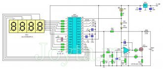
Figure 1 – Three-phase bridge rectifier circuit
The three-phase bridge circuit is currently the most widely used. This is due to the fact that it has better technical and economic indicators compared to other schemes.
Good quality of the rectified voltage is the same as in a six-phase midpoint rectification circuit, achieved by using six valves, but the rectifier operates with one three-phase winding. That is, if necessary, you can work without a transformer, directly from a three-phase alternating current network. The bridge circuit can be represented by two three-phase circuits with the middle output connected in series. The first rectifier (1) is assembled on thyristors VS1, VS3, VS5 - which are combined into a cathode group. The second rectifier (2) – VS2, VS4, VS6 they are combined into an anode group.
When the rectifiers are connected in series, the rectified voltage doubles:
Ud0=Ud0I+Ud0II ,
In addition, when connected in series, equalizing currents are eliminated - an equalizing reactor is unnecessary.
Three-phase valve circuit (Larionov circuit)
to contents
Valves 1,3,5 form the cathode group, and valves 2,4,6 form the anode group (Fig. 1). From the cathode group, the current passes through the valve whose anode is supplied with a greater positive voltage.
Comment
.
It should be noted that the numbering of the valves in this circuit is not random, but corresponds to the order in which they enter into operation, provided that the phasing of the transformer is observed (Fig. 1).
Fig.1. Three-phase push-pull valve circuit
At any time interval, two valves must be turned on - one from the cathode group and the other from the anode group. Alternate operation of different pairs of valves in the circuit leads to the appearance of a rectified voltage at the resistance, consisting of parts of the linear voltages of the secondary windings of the transformer (axis 2 in Fig. 2) [1, 2].
From Fig. 2 (axes 1 and 2) it is clear that the commutation moments coincide with the moments of line voltages passing through zero (when two phase voltages are equal).
In the interval (0-01), the greatest positive value is the voltage supplied to the anode of valve 1, and the greatest negative value is the voltage supplied to the cathode of valve 6. Therefore, in this interval, valves 1 and 6 are simultaneously turned on. Through valve 1, positive voltage is supplied to the lower terminal, and through valve 6, negative voltage is supplied to the upper terminal of the resistance. Therefore, the rectified voltage
.
Fig.2. Current and voltage curves at
At point 01 the voltage is , so valve 2 is turned on from the anode group. Since to the right of point 01 the voltage has the greatest negative value, valve 6 turns off. In the interval (01-02) valves 1 and 2 and rectified voltage are simultaneously turned on
.
Obviously, the amplitude of the rectified voltage
.
A line voltage is applied to each closed valve, so the amplitude of the reverse voltage
.
Number of ripples of rectified voltage.
The DC component of the rectified voltage (average value) is calculated for the rectified voltage repeatability interval equal to:
| (1) |
where is the effective value of the phase voltage of the secondary windings of the transformer.
Effective value of the secondary winding current (axis 6)
| , | (2) |
Effective value of the primary winding current
| (3) |
Maximum valve current value
| (4) |
Average valve current
| (5) |
Valve current effective value
| (6) |
Let the control angle be . In a three-phase bridge circuit on controlled valves, unlocking pulses arrive with a delay by an angle relative to the zeros of linear voltages or the moments of intersection of sinusoids of phase voltages (Fig. 3).
As a result of the delay in the switching moments of the thyristors by an angle, the average value of the rectified voltage formed from the corresponding parts of the linear voltages decreases.
As long as the curve of the instantaneous values of the rectified voltage remains above zero, which corresponds to the control angle change range, the rectified current will be continuous regardless of the nature of the load. Therefore, at angles, the average value of the rectified voltage for active and active-inductive loads will be equal to
| (7) |
At angles and active load, intervals with a zero value appear in voltage and current (Fig. 4), i.e. the operating mode with intermittent rectified current begins.
The average rectified voltage for this case can be expressed as follows:
| (8) |
Where
.
Fig.3. Diagrams of currents and voltages at angles
Comment.
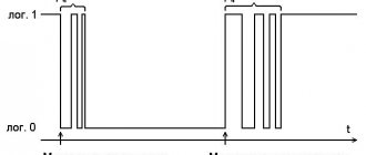
In the intermittent current mode, to ensure the operation of this circuit, as well as for its initial startup,
double
unlocking pulses should be applied to the gates of the circuit at intervals or single ones, but with a duration greater than . This is explained by the fact that in order to form a closed circuit for the flow of current id, it is necessary to ensure that the valve of the anode group and the valve of the cathode group are turned on simultaneously.
Fig.4. Stress diagrams at angles and
When the angle changes from 0 to the adjustment characteristic for active and active-inductive loads is described by the formula
.
With an active-inductive load and angles , if or the ratio is such that a continuous current mode is ensured, the average value of the rectified voltage is also determined by the formula
.
When the average value becomes equal to zero, this means that this corresponds to the equality of the areas of the positive and negative sections of the rectified voltage curve, which indicates the absence of a constant component in it (curve 2 in Fig. 5).
Starting from the corner with active
load, the adjustment characteristic is described by the formula (curve 1 in Fig. 5)
.
Fig.5. Adjustment characteristics: 1 – with active load; 2 – with active-inductive load
The shaded area in Fig. 5 corresponds to a family of control characteristics in the intermittent current mode id at various values of .
Let us assume that the inductance is so large that the load current does not have time to pass through zero before the next valve is opened. When the current does not pass through zero, it increases from interval to interval and is established over a number of periods (usually three or four).
In a three-phase bridge circuit, voltage is connected to the load
,
where , and the angle of natural valve activation at is .
The current through the load is determined by the differential equation
| (9) |
General integral for solving equation (9)
| (10) |
Where ; — load angle; — time constant of the load circuit; – integration constant, determined in each specific case from the initial conditions.
To determine the current in any time interval, it is convenient to use difference equations.
In general, a voltage with a back EMF can be connected to the load
,
where is the back-EMF, for example, a battery or a DC motor armature. When exposed to back-EMF, it is possible to obtain a regime of intermittent currents, where equations (9) and (10) are invalid.
LITERATURE
2. Arkhangelsky N.L., Kurnyshev B.S., Litvinsky A.N.
. Characteristics and protection of semiconductor converters/ – Ivan. state energy univ. – Ivanovo, 2000. – 96 p.
Control questions
1. Which voltage - phase or linear - affects the rectified voltage form?
2. From what stress point is the opening angle of the valves measured and what is its maximum value?
3. At what angles? will the rectified current be continuous regardless of the nature of the load?
4. Why should double gate pulses be applied at intervals to start a bridge rectification circuit?
5. Find the average and extreme values of the rectified voltage if it is known that , .
Answer:
297 V; 306 V – 266 V.
6. Find the effective value of the current in the secondary and primary windings of the power matching transformer, if it is known that , , .
Answer:
16.1 A, 9.15 A.
7. Find the maximum, average and effective values of the valve currents, if it is known that , , , .
Answer:
, , .
8. Find the maximum control angle for a three-phase bridge circuit with a load.
Answer:
.
to contents
Did you know,
that when some researchers trying to reconcile relativism and ethereal physics say, for example, that the cosmos consists of 70% “physical vacuum”, and 30% of matter and field, then they fall into a fundamental logical contradiction. This contradiction is as follows. Matter and field are not something separate from the ether, just as the human body is not something separate from the atoms and molecules of its components. It is these atoms and molecules assembled in a certain order. Also, matter is not something separate from elementary particles, but it consists of them as basic matter. Also, elementary particles consist of ether particles as the basic matter of the lower level. Thus, everything that exists in the universe is ether. Ether 100%. Elementary particles are made of it, and everything else is made of them. Read more in the FAQ on ethereal physics.
Operating principle of a diode bridge
Diode in AC voltage circuit
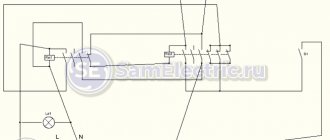
So, in the article about the diode, we looked at what will happen at the output of the diode if alternating current is applied to it. To do this, we even assembled a circuit like this, where G is a sinusoidal generator. The signal has already been removed from terminals X1 and X2.
We applied alternating voltage to the diode.
And at the output after the diode we received such a signal.
That is, we got it like this.
Yes, we got direct current from alternating current, but was it worth it? In this case, we got a constant pulsating current , where half of the signal power was completely cut out.
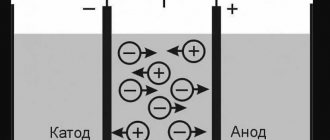
How a diode bridge works in theory
As you know, alternating current changes its direction several times per second. Therefore, it can be divided into positive half-waves and negative half-waves. I marked the positive half-waves in red, and the negative half-waves in blue.
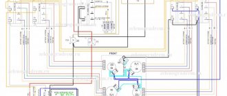
In order for the diode bridge to work, it needs some kind of load. Let this be a resistor. Therefore, when a positive half-wave arrives at the diode bridge, the current flow through it will look like this.
As you can see, with the positive half-wave there are no diodes involved, which I showed with a dashed line.
After the positive half-wave comes a negative half-wave, and in this case the current flow in the diode bridge looks like this.
In this case, the diodes that worked at a positive half-wave, they rest at a negative half-wave). Another pair of diodes takes over the baton. You can even say that in a diode bridge they work in pairs. One pair of diodes operates on the positive half-wave, and the other pair operates on the negative half-wave.
Pay attention to the load. The same polarity of current always comes to it under any set of circumstances.
Diode bridge operation in practice
Let's see what happens at the output of the diode bridge if we apply an alternating voltage to it. To do this, take 4 simple silicon diodes and connect them into a diode bridge. It is important that the diodes are of the same brand.
We will apply an alternating voltage to the input of the diode bridge and see what we get at the output.
So, I give this signal to the input.
At the output I get a constant pulsating voltage.
Here we see that the negative half-wave in the diode bridge is not cut off, but turns into a positive one. The signal power is not lost in this case, since the negative half-wave is simply inverted into a positive half-wave. Well, isn't it a miracle?
An observant reader may also notice that the signal amplitude has dropped slightly. If we supplied a sinusoidal signal with an amplitude of 6 Volts to the input, then at the output of the diode bridge we have a little less than 6 Volts, or rather, about 4.8 Volts. Why did it happen? The point is that the voltage drops across the silicon diode is 0.6-0.7 Volts. Since alternating voltage passes through 2 diodes at each half-wave, each diode drops 0.6 Volts. 2×0.6=1.2 Volts. 6-1.2=4.8 Volts.
Now you can draw your drawing with pride.