Definition and essence of the problem in electronics
Contact bounce occurs when you press a button and switch; it occurs due to actual vibrations of the contact plate as it moves. Any switch is designed so that it has a moving and a fixed contact. As the name implies, the one that is connected to a pusher or lever, which is already pressed by a person or mechanism when the device is operating, is called movable.
Since the buttons have a mechanical device, their quality determines how accurately they respond to pressing. However, in any case, it is impossible to completely eliminate the chattering phenomenon. What does it lead to?
If a key controls some kind of electronic device with a digital input, for example, a microcontroller, logic element, etc., then its input recognizes as many presses as the number of pulses sent as a result of bouncing.
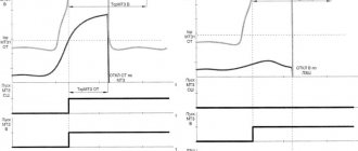
An example of a contact bounce oscillogram is shown in the figure below:
| Sketch (code) for lesson 8. Arduino: Bouncing - software elimination.ino | 1 Kb | 59 | You can download the file. |
Eliminating contact bounce in a water meter | Life, business and IT
In order to understand how to eliminate button bounce, let’s look at the figure that shows button bounce. As you can see, the chatter does not last long, and if you make a short delay after pressing the button and read the value again, the read value will already be in a steady state.
Expert opinion
It-Technology, Electrical power and electronics specialist
Ask questions to the “Specialist for modernization of energy generation systems”
Tormenting the 5576ХС4Т - part 5 - suppressing button bounce: nabbla1 - LJ Hardware de-bouncing of a button is a change in the connection diagram by installing elements that can eliminate bounce. Ask, I'm in touch!
Is there a way to deal with all of this?
To effectively combat this problem, we can use a hardware or software solution. The first option includes the following:
- Installation of capacitors parallel to the input. This will help reduce the response to pressing in conditions of excessive capacity and partially eliminate chatter in the case of small capacity.
- The use of an amplifier with positive feedback - a Schmidt trigger. This is difficult to do in the case of a completed circuit, but if you bother, you will be very pleased with the result.
There is a way - the Schmidt trigger. We have already said above what this is. Familiarize yourself with the diagram that is used most often.
Well, we’ll give you some more diagrams, look and understand clearly how you can avoid bouncing of electronic contacts. The second method that can correct the situation, as we said at the beginning of the long journey, is the use of a software method.
The essence of this method is that you need to write a special code, the meaning of which is as follows: the signal conversion is read, the exposure is for a specifically specified period, and then the signal is read again.
You can download a software debounce circuit for the Arduino IDE.
Button bounce errors
How will rattling affect our project? Yes, in the most direct way - we will receive a completely random set of values as input. After all, if we read the value from the button continuously, in each new working cycle of the loop function, then we will notice all the “spikes” and “drops” of the signal. Because the pause between two calls to loop is microseconds and we will measure all the small changes.
If we want to track the situation when the button was released after being pressed, we will get a lot of false signals - it will be “pressed and released” dozens of times, although we only pressed it once.
Here is an example of a sketch in which a bouncing error will certainly appear. We will be able to see in the port monitor in the first moments after pressing a whole set of zeros and ones in a random sequence (it doesn’t matter what 1 means - pressing or releasing the button, the very fact of the appearance of chaos is important).
Naturally, such behavior will not lead to anything good and we need to come up with a way to combat rattling. There are two methods in our arsenal: software and hardware. The first one is quite simple, but it cannot always be used in real projects. The second is more reliable, but requires significant changes in the circuit. Let's look at both methods in more detail.
Programming
The code implementing such a principle can be different, here is one of the possible ones, it is “pumped” by comparing the current value with the previous one (this is how pressing and releasing a button is tracked) [taken from: Software debouncing of buttons snigelen February 5, 2015 , and slightly modified to STM32].
three global variables are used
/********* PV **********/ /* PA0 */ uint8_t pres_pa0; uint8_t prev_pa0; uint8_t cnt_pa0; /* PA7 */ uint8_t pres_pa7; uint8_t prev_pa7; uint8_t cnt_pa7; /* Other */ uint8_t counter; /********************************/
And here is the function itself with a bunch of arguments (overloaded, but convenient):
/** * @brief Debounce function for button * @note Perform it every 10-20ms (eg in timer's interrupt) * In main loop check first variable ((*pres_px), if (it > 0) NULLify it and execute required code * @param Three global variables, IDR register, Bit for check (eg &pres_pa0, &cnt_pa0, &prev_pa0, GPIOA->IDR, GPIO_IDR_ID0) * @retval no */ void Debounce(uint8_t *pres_px, uint8_t *cnt_px, uint8_t *prev_px, uint32_t GPIOx_IDR, uint32_t GPIO_IDR_IDx) { /* Read current state */ uint8_t cur_px = (~GPIOx_IDR & GPIO_IDR_IDx) != 0; /* If level has changed */ if (cur_px != *prev_px) { /* Increase counter */ ( *cnt_px)++; /* If consecutive 4*10 = 40ms approved */ if (*cnt_px >= 4) { /* The button have not bounced for four checks, change state */ *prev_px = cur_px; /* If the button was pressed (not released), tell main so */ if (cur_px != 0) { *pres_px = 1; } (*cnt_px) = 0; } } else { /* Reset counter */ *cnt_px = 0; } }
I took a cool charged MiniF4 debug board (MK: STM32F411CEU6 ). Well, now you need to configure the pin(s) as an input (a button is connected to it) and one as an output (an LED is connected to it):
/* GPIOC 13 OUT PP */ /* Clock GPIOC */ RCC->AHB1ENR |= RCC_AHB1ENR_GPIOCEN; /* 01: General-purpose output */ GPIOC->MODER |= GPIO_MODER_MODE13_0; GPIOC->MODER &= ~GPIO_MODER_MODE13_1; /* 0: Output push-pull */ GPIOC->OTYPER &= ~GPIO_OTYPER_OT13; /* 00: Low speed */ GPIOC->OSPEEDR &= ~GPIO_OSPEEDER_OSPEEDR13; /* 00: Np pull-pull up, pull-down */ GPIOC->PUPDR &= ~GPIO_PUPDR_PUPD13; /**********************/ /* GPIOA 0 IN PU */ /* Clock GPIOA */ RCC->AHB1ENR |= RCC_AHB1ENR_GPIOAEN; /* 00: Input (reset state) */ GPIOA->MODER &= ~GPIO_MODER_MODE0_0; GPIOA->MODER &= ~GPIO_MODER_MODE0_1; /* 01: Pull-up */ GPIOA->PUPDR |= GPIO_PUPDR_PUPD0_0; GPIOA->PUPDR &= ~GPIO_PUPDR_PUPD0_1;
Also interrupt from Timer 11 , frequency 100 Hz (with APB2 = 16000000 Hz):
/* Clock Tim11 */ RCC->APB2ENR |= RCC_APB2ENR_TIM11EN; /* T=10ms */ TIM11->PSC = 160-1; TIM11->ARR = 1000-1; /* Update Interrupt Enable */ TIM11->DIER |= TIM_DIER_UIE; /* Counter enable */ TIM11->CR1 |= TIM_CR1_CEN; /* Tim11 Interrupt enable */ NVIC_EnableIRQ(TIM1_TRG_COM_TIM11_IRQn);
In the interrupt we perform the function:
void TIM1_TRG_COM_TIM11_IRQHandler(void){ if(TIM11->SR & TIM_SR_UIF){ /* GPIOA-0 KEY */ Debounce(&pres_pa0, &cnt_pa0, &prev_pa0, GPIOA->IDR, GPIO_IDR_ID0); Debounce(&pres_pa7, &cnt_pa7, &prev_pa7, GPIOA->IDR, GPIO_IDR_ID7); TIM11->SR &= ~TIM_SR_UIF; } }
And in the main loop, with each press, the state of the LED will change and the value of the variable will be incremented (purely for example):
while(1){ if(pres_pa0){ pres_pa0 = 0; GPIOC->ODR ^= GPIO_ODR_OD13; counter++; } }
Full code:
#include "main.h" /****** Prototypes ******/ void Cnf_GPIO(void); void Cnf_TIM11(void); void Debounce(uint8_t *pres_px, uint8_t *cnt_px, uint8_t *but_px, uint32_t GPIOx_IDR, uint32_t GPIO_IDR_IDx); /********************************/ /********** PV *************/ / * PA0 */ uint8_t pres_pa0; uint8_t prev_pa0; uint8_t cnt_pa0; /* PA7 */ uint8_t pres_pa7; uint8_t prev_pa7; uint8_t cnt_pa7; /* Other */ uint32_t counter; /********************************/ int main(void) { /* Configuration */ Cnf_GPIO(); Cnf_TIM11(); while(1){ if(pres_pa0){ pres_pa0 = 0; GPIOC->BSRR |= GPIO_BSRR_BR13; counter++; } if(pres_pa7){ pres_pa7 = 0; GPIOC->BSRR |= GPIO_BSRR_BS13; counter—; } } } /****************************************************** *******/ void Cnf_GPIO(void){ /* GPIOC 13 OUT PP */ /* Clock GPIOC */ RCC->AHB1ENR |= RCC_AHB1ENR_GPIOCEN; /* 01: General-purpose output */ GPIOC->MODER |= GPIO_MODER_MODE13_0; GPIOC->MODER &= ~GPIO_MODER_MODE13_1; /* 0: Output push-pull */ GPIOC->OTYPER &= ~GPIO_OTYPER_OT13; /* 00: Low speed */ GPIOC->OSPEEDR &= ~GPIO_OSPEEDER_OSPEEDR13; /* 00: Np pull-pull up, pull-down */ GPIOC->PUPDR &= ~GPIO_PUPDR_PUPD13; /**********************/ /* GPIOA 0 IN PU */ /* Clock GPIOA */ RCC->AHB1ENR |= RCC_AHB1ENR_GPIOAEN; /* 00: Input (reset state) */ GPIOA->MODER &= ~GPIO_MODER_MODE0_0; GPIOA->MODER &= ~GPIO_MODER_MODE0_1; /* 01: Pull-up */ GPIOA->PUPDR |= GPIO_PUPDR_PUPD0_0; GPIOA->PUPDR &= ~GPIO_PUPDR_PUPD0_1; /* GPIOA 7 IN PU */ /* Clock GPIOA */ RCC->AHB1ENR |= RCC_AHB1ENR_GPIOAEN; /* 00: Input (reset state) */ GPIOA->MODER &= ~GPIO_MODER_MODE7_0; GPIOA->MODER &= ~GPIO_MODER_MODE7_1; /* 01: Pull-up */ GPIOA->PUPDR |= GPIO_PUPDR_PUPD7_0; GPIOA->PUPDR &= ~GPIO_PUPDR_PUPD7_1; } void Cnf_TIM11(void){ /* Clock TIM11 */ RCC->APB2ENR |= RCC_APB2ENR_TIM11EN; /* T=10ms f=100Hz */ TIM11->PSC = 160-1; TIM11->ARR = 1000-1; /* Update Interrupt Enable */ TIM11->DIER |= TIM_DIER_UIE; /* Counter enable */ TIM11->CR1 |= TIM_CR1_CEN; /* TIM11 Interrupt enable */ NVIC_EnableIRQ(TIM1_TRG_COM_TIM11_IRQn); } void TIM1_TRG_COM_TIM11_IRQHandler(void){ if(TIM11->SR & TIM_SR_UIF){ /* GPIOA-0 KEY */ Debounce(&pres_pa0, &cnt_pa0, &prev_pa0, GPIOA->IDR, GPIO_IDR_ID0); Debounce(&pres_pa7, &cnt_pa7, &prev_pa7, GPIOA->IDR, GPIO_IDR_ID7); TIM11->SR &= ~TIM_SR_UIF; } } /** * @brief Debounce function for button * @note Perform it every 10-20ms (eg in timer's interrupt) * In main loop check first variable ((*pres_px), if (it > 0) NULLify it and execute required code * @param Three global variables, IDR register, Bit for check (eg &pres_pa0, &cnt_pa0, &prev_pa0, GPIOA->IDR, GPIO_IDR_ID0) * @retval no */ void Debounce(uint8_t *pres_px, uint8_t *cnt_px, uint8_t *prev_px , uint32_t GPIOx_IDR, uint32_t GPIO_IDR_IDx) { /* Read current state */ uint8_t cur_px = (~GPIOx_IDR & GPIO_IDR_IDx) != 0; /* If level has changed */ if (cur_px != *prev_px) { /* Increase counter * / (*cnt_px)++; /* If consecutive 4*10 = 40ms approved */ if (*cnt_px >= 4) { /* The button have not bounced for four checks, change state */ *prev_px = cur_px; / * If the button was pressed (not released), tell main so */ if (cur_px != 0) { *pres_px = 1; } (*cnt_px) = 0; } } else { /* Reset counter */ *cnt_px = 0; } }
Hardware debouncing
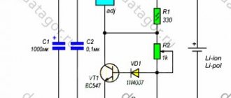
Various approaches are used to eliminate hardware contact bounce. The simplest option is to use an RC chain to smooth out high-frequency short bursts during transient processes. Let's look at the diagrams from the article.
Contact bounce suppression for water meter (Arduino/ESP8266/EPS32)
You can play around with how the circuit works here. When the button is open, capacitance C1 is charged through resistance R1. The input of the inverting Schmitt trigger is +VCC. The output is correspondingly 0.
Contact bounce suppression for water meter (Arduino/ESP8266/EPS32)
The circuit is almost the same, but when the button is closed, capacitance C2 is discharged to ground through resistance R4, so the current flowing through the contacts is already safely small for the contacts: I = U/R = 5/1000 = 5 mA.
t is the discharge time from the Vdc level to Vc. Vc is the voltage at which the controller identifies the voltage level as logical zero. I took Vc = 0.5 V. The article describes in detail the levels for the ESP8266. I took a slightly lower voltage, instead of 0.8 V for the voltage below which the ESP8266 considers the level to be logic zero.
If the capacitance is increased from 0.01 µF to 0.1 µF, then the time it takes to discharge capacitor C1 to the V0 level will already be 180 ms, which is quite a lot. However, in this case the processes are so slow that such a container can be left. Its increase, and, accordingly, inertia, better smoothes out short bursts, reducing the likelihood of false alarms.
Resistor R2 is also necessary to protect the microcontroller input in case it sets the logical level to 1 at the input when the button is shorted to ground. Without this resistor, significant current would begin to flow through the microcontroller input, which would damage the input.
Expert opinion
It-Technology, Electrical power and electronics specialist
Ask questions to the “Specialist for modernization of energy generation systems”
How to get rid of contact bounce when connecting a button to Arduino Figure 2 clearly shows a voltage oscillogram as a result of switching electric current due to pressing the button. Ask, I'm in touch!
What voltage is needed to replace the relay?
Most of them are rated 12v
, usually the range is 12-15V. The actual voltage required for the relay to operate is usually a little below 12V. This is why your accessories may work with the key on and the engine off, usually with the lights on the actual voltage is a little below 12V.
Interesting materials:
Are detergents expiring? Are Klondike bars expiring? Has Adobe AIR reached the end of its life? What is the service life of LG washing machines? Is SSAO good or bad? Is SSAO better than HBAO? Do SSD drives wear out faster? SSD RAM or ROM? USA - 110 or 120? Is SSC MTS held every year?
Contact bounce and methods for suppressing bounce.
- Instead of programmatically polling the state of the inputs in the loop, use a more beautiful option with interrupts. If you use a debounce circuit, this method will work correctly. An example of code using interrupts is described in the article.
- Drive the ESP8266/ESP32 into deep-sleep, indicating the time after which it should wake up to process the state of the inputs. In this case, there is no need to use hardware debouncing. When exiting hibernation, the ESP8266 may have already missed the activation of the reed switch, so you need to poll the current state of the inputs, and then go into hibernation again. The hibernation time must be less than the minimum duration of the reed switch activation. You need to make sure that after the reed switch is activated, if you immediately turn off the water, it will remain in the closed state. If it turns off, then you need to choose the deep sleep time taking into account this “force majeure”.
- Drive the ESP8266/ESP32 into deep-sleep and bring it out of this state by removing data from the reed switches through the contact debouncing circuit and applying a pulse to the EXT_RSTB input. To do this, you can use the free elements of a Schmitt trigger. I will describe the circuitry for this option in another article.
- Considering that the ESP8266/ESP32 start instantly, you can even connect the power circuit to the reed switch. Those. turn on the circuit when one of the reed switches is closed.
Water meter circuit on ESP8266 (Wemos D1 mini)
Diagram and example of a printed circuit board in the EasyEDA project. I left the I2C inputs unoccupied to connect the indicator.
Water meter circuit on Wemos D1 mini (ESP8266) with hardware elimination of contact bounce on the Schmitt trigger
I made the diagram on Wemos breadboard.
Water meter shield circuit board on Wemos D1 mini (ESP8266) with hardware contact debouncing on the Schmitt trigger
An example of a printed circuit board generated by autorouting in EasyEDA.
Printed circuit board shield of a water meter on Wemos D1 mini (ESP8266) with hardware de-bouncing of contacts on a Schmitt trigger