Calculation of a welding transformer on a toroidal core
The transformer is the main component of the welding machine, regardless of its design.
When making this element yourself, many questions arise: How to choose the shape of the magnetic circuit? What kind of winding wire is required? How to calculate the required number of turns? A toroidal transformer has a number of advantages over other types of transformers:
- Uniform distribution of windings;
- Weight reduction by 20...30% while maintaining power;
- Reduced currents H.H. 10...20 times;
- High efficiency;
- Reducing stray fields;
- Low noise level.
If you put some effort into creating a toroidal transformer with your own hands, you can get your own unique set of device characteristics that will satisfy all your needs when working with welding. And even more than that, you can take into account the current realities of our reality, such as, for example, low voltage in the network of your home.
Using the formulas and methods given in our article, you will receive a practical guide to calculating a welding transformer on a toroidal core.
Calculation method - step-by-step instructions
The calculation of the toroidal transformer itself is divided into two parts:
- You can directly calculate the power of a toroidal core in order to determine it; if you have a specific core, or a given power, then determine the dimensions of the future transformer.
- Calculation of the electrical part itself, which includes the number of turns in the windings, as well as what cross-section will be used in the windings and wire material.
Core calculation
We will produce it using a formula that already includes constants to simplify the understanding of its results. Next, all that remains is to substitute only variable values into the formula below, namely:
We recommend! How to make welding electrodes with your own hands
“P=1.9*Sc*So” , where:
- P is the power that can be obtained using a core with such overall dimensions
- 1.9 – the result of mathematical operations on all constants for this type of transformers
- Sc - core area, unit of measurement square centimeters
- So is the area of the hole in the core body, in “sq. cm."
Formulas for calculating the cross-sectional area of a toroidal core
If the transformer made will have the main purpose of welding, then the dimensions of its core must be adequate, otherwise the resulting power of the device will not be enough to perform its functions. For example, take the following values and use a calculator to calculate. "P=1.9*70*70=9310 Watt"
Let's determine the number of turns of the primary winding
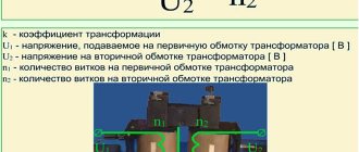
First of all, we will consider the calculation with a single primary winding, without adjustment. To do this, we first find out how many winding turns a toroidal transformer must have to produce 1 volt of voltage. Let's apply the following formula. K=35/Sc , where:
- K – number of turns per 1 volt of voltage.
- 35 is a constant that is the same for all types of toroidal cores.
- Sc is the area of the core, the unit of measurement is square centimeters.
Thus, if we have a core with an area of 70 "sq. see", then substituting the values in the formula, we get the following situation. “K=35/70=0.5” turns for each volt, and accordingly we find out the volume of the primary winding by applying the appropriate formula. “W1=U1*K” , where:
- W1 is the number of turns in the first winding.
- U1 is the required voltage at this point.
- K – number of turns per 1 volt of voltage.
“W1=220*0.5=110” – turns. Taking into account the fact that we are carrying out calculations for a welding transformer, we will take the operating voltage of the secondary equal to 35 volts, then based on a similar formula, we will obtain.
“W2=35*0.5=17.5” – turns.
Calculation of the cross-section of the wires used
To calculate the required cross-sections, you need to understand what current will flow through them, this is the only parameter that affects the thickness of the material used, so, calculating the amount of current in the transformer windings: “I AC = 9310 Watts/220 Volts = 42.3 Amperes” With a secondary winding several more complicated, everything must rely on the arc voltage and welding current.
“I weld.=(29 Volt-14)/0.05=300 Ampere” , where 29 volts is the average value of the welding arc. Now we check whether such power is possible for our device: 300 Amperes * 29 Volts = 8700 Watts.
This value fits well into the power of the toroidal transformer that we are calculating, so we consider 300 Amps to be the secondary winding current. Having carried out these simple calculations, for which you don’t even always need a calculator, you can proceed to determining the cross-section of the wires and their material.
From guidance documents such as, for example, “PUE”, it is known that for long-term operation, 1 square millimeter of copper cross-section is required for every 5 amperes of current, and when using aluminum, 2 amperes. Based on these data, we calculate the cross-section of the wires in the device for copper:
- Primary winding = 42.3/5 = 8.46 sq. mm, the closest cross-section standard is 10.
- Secondary winding=300/5=60 sq. mm, choose the next standard section in the direction of increase - 70.
We apply the load duration condition of 40 percent, since no one works under load all the time. In this case, the cross section can be reduced by half, then we get:
- 8.46/2=4.23 the nearest cross-section standard is -6 sq. mm.
- 60/2=30 next standard 35 sq. mm.
How to simplify the task of winding turns on a core
Knowing how to create a transformer in all details and with all the data, all that remains is to move on to practical work, but winding turns is a rather labor-intensive process that requires special concentration. The correctness of winding is also important and directly affects the characteristics of the resulting device.
But for such cases, there is a special device to help people, a machine for winding toroidal transformers, the price of such a device is not high, but it is not easy to buy, so home-made devices are often found on the market, and if you read the relevant literature, you can try to make this machine yourself .
Self-production of the unit
Before you begin creating such a unit, you need to prepare all the necessary tools and materials. To make a higher-quality model, you may even need a sewing machine, a strong needle and ordinary matches, but such parts can be found in almost every home.
The main consumable material is iron; the basic parts of the transformer are made from it. To work, you will need high-quality steel, which should be in the shape of a torus. Don't forget about a good wire with varnish insulation. Reliable fixation cannot be done without PVA glue and masking tape.
It is also worth considering that the quality of the windings depends on fabric-based electrical tape. It is also worth purchasing a high-quality wire in rubber or silicone insulation. This element will be needed to reliably connect all ends of the winding.
Preparation of transformer steel
It may seem to novice craftsmen that it is extremely difficult to obtain a basic structural element, but in practice everything is completely different. The fact is that even ordinary metal collection points often have inoperative voltage stabilizers. During the Soviet period, they were very common, as they were used in black and white televisions, which extended the performance of picture tubes.
The serviceability of such a device does not matter at all, since only toroidal transformers, which are located in the internal compartment of the stabilizer, are of particular value. It is this part that the craftsmen use as the basis for the entire structure.
On the way to removing transformers there is always a winding made of aluminum wire. Do not forget that the core also needs preparatory work. The craftsman must round off the sharp edges of this part as much as possible, since the varnish insulation may be damaged during the winding process. Fabric-based electrical tape must be laid over transformer steel. In this case, only one insulating layer is needed.
Winding rules
Before starting this type of work, you need to make a calculation of the toroidal transformer based on the cross-section of the core. Of course, the master can use special online calculators, of which there are a lot on the Internet. But you can choose a simpler option, where for all calculations you only need to prepare a ruler and a calculator.
Of course, it may have some errors, since the calculation does not imply compliance with all those factors that occur in nature. The main thing is to adhere to the rule that the total power in the secondary coil should not exceed similar indicators in the first winding.
When the master has reached this stage and needs to wind the toroidal unit, he should be extremely careful, since this process is quite labor-intensive. The best option is when it is possible to disassemble the magnetic circuit yourself and reassemble it after winding.
Otherwise, you can resort to using a regular spindle, on which you need to carefully wind a certain amount of pre-prepared wire. Only after this can the spindle be passed through the torus the required number of times, evenly laying out the turns of the windings. Of course, it will take a lot of time to implement such an idea, but the result is worth it.
It is worth noting that in standard situations, craftsmen carry out additional insulation of the toroidal core from the windings (even if varnished wire is used). Particularly popular is high-quality electrical cardboard , which meets all GOST 2824 standards. The thickness of this material is within 0.8 mm.
During the work, the masters adhere to the following scheme:
- The cardboard is carefully wound onto the core with a slight capture of the previous turn. The end of the material must be fixed with keeper tape or PVA glue.
- All ends of the core must be protected with cardboard washers with small cuts from 10 to 20 mm, step length - 35 mm. Both the outer and inner edges must be covered with small stripes. It is worth noting that the technological washers are fixed at the finishing stage, and all the rubberized teeth are bent. A keeper tape is wound over the entire structure.
- If the cuts were made right on the strips, then there should be a small margin to achieve a greater end height. All rings must be attached strictly in width; they are placed on top of the bends.
- In rare cases, rings can be made of special electrical plywood or thick textolite. The vulnerable inner and outer edges are protected with cardboard strips with slight bends at the edges. There should be a small air gap between the first turns of the winding and the core. This approach is especially important in cases where the edges under the wire are worn out. This way, the vulnerable current-carrying part will never touch the toroidal core. A keeper tape must be wound onto the top layer. In some cases, craftsmen prefer to smooth the outer edge of the rings, due to which the winding of the corners goes smoothly.
If the transformer has increased power, then the copper wire should be of rectangular cross-section. This approach allows you to save free space. The core must be thick so that it does not melt when a large voltage passes through it.
Calculation of a welding transformer on a toroidal core - Metals, equipment, instructions
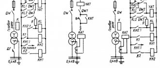
There are a great many different schemes for welding units, from the simplest to inverters.
To create a homemade welding machine, it is better to choose a simple and highly reliable circuit that does not contain complex and expensive electronics.
But in any case, in addition to the diagram, a preliminary calculation of the welding transformer will be required. Only after this can we begin its practical production.
Welding transformer diagram.
The specificity of the calculation of such transformers is that the parameters of their components in most cases are selected in accordance with existing parts - most often with magnetic circuit data.
Therefore, standard calculation methods that were developed for an industrial transformer are not always applicable for a homemade welder.
This is especially evident when one or another parameter goes beyond the standard boundaries.
Selecting the maximum welding current value
Table 1. Characteristics of welding transformers.
First of all, you need to decide what maximum value of welding current the transformer will be designed for.
The relationship between the thickness of the metals being welded, the diameter of the electrodes and the welding current is shown in Table 1.
Considering that using a single-phase transformer, it is almost impossible to obtain a current of more than 200 A, the home craftsman has to limit himself to electrodes with a diameter of no more than 4 mm. Most often 3 mm.
The most suitable upper limit of the welding current should be set and the windings should be wound at the corresponding power.
It should be clearly understood that with its growth, the weight of the core, cross-section and cost of the wire increase. In addition, a more powerful transformer heats up more and wears out faster.
And not every network can withstand such a load. The golden mean is a device with an output current of 110-120 A.
Other performance characteristics
Three-phase core transformer.
The maximum output current is the main characteristic of any welder, but along with it, other important parameters should be determined:
- Range of regulation of the output current value. In home-made devices, a number of stages are usually created - from 50 A to the upper limit.
- Open circuit voltage. The higher it is, the easier it is to ignite the arc. For safety reasons, should not exceed 80 V.
- The rated output voltage that is necessary for stable arcing. For welding thin metals, this voltage should be lower and vice versa.
- Power – consumed and output. The smaller their difference, the higher the efficiency of the manufactured transformer, the better it is.
- The nominal operating mode characterizes the duration of continuous operation. For a homemade welding transformer it does not exceed 20-30%. The nominal mode of 20% means that out of 10 minutes of working time, 2 minutes can be cooked, and the remaining 8 minutes the transformer must be cooled at idle.
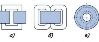
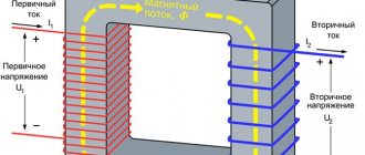
Transformer core structure
Depending on the shape of the magnetic circuit, the following types of transformers are distinguished:
- rod;
- armored;
- toroidal.
Basic concepts and classification of transformers.
On a core transformer, the windings surround the core bars. On the armored one, on the contrary, the magnetic circuit partially wraps around the windings. In a toroidal winding, the windings are distributed evenly along the magnetic circuit.
Armor and rod cores are made from separate thin plates insulated from each other. Material – transformer steel. Toroidal ones are wound in the form of a roll from a tape made of the same transformer steel.
The most important characteristic of any core is its cross-sectional area. The power of the transformer largely depends on it. For a rod magnetic circuit, its cross-sectional area is understood as the area of any of the rods, and for a toroidal one, the torus. For an armored one, this is the cross-sectional area of its middle rod.
The efficiency of rod-type transformers is higher than that of armored ones. In addition, they have better cooling conditions for the windings and, therefore, permissible current densities in the windings. Therefore, welding transformers, as a rule, are rod-based.
But more and more often they are trying to use a toroidal core for its manufacture. The fact is that the weight and dimensions of such a welder are almost one and a half times less than a rod welder, all other parameters being equal.
But here difficulties arise with winding it.
Calculation of a welding transformer
Winding diagram of a welding transformer.
Since when making a welder yourself you have to be content with the available magnetic cores, it makes no sense to make a strict calculation.
Most often, the magnetic properties and other characteristics of transformer steel are not reliably known. Magnetic permeability alone, which is easy to determine experimentally, is not enough for an accurate calculation.
Therefore, it is more rational to limit ourselves to an approximate calculation.
First, the required electrical power is assessed. The main measure here is the maximum value of the welding current, which, in turn, is determined by the largest diameter of the electrode (see table 1). Electric power of the welder:
P = Ud * Im,
where Ud is the arc voltage (usually the value is 25 V), Im is the maximum welding current. For example, for a transformer rated for current up to 150 A, the electrical power should be:
P = 25 V * 150 A = 3750 W.
The overall power of the transformer, depending on the parameters of the magnetic circuit, must necessarily be greater than the electrical power. It is the overall power that the core can “pull”. When calculating, the following formula is most often used as the initial formula, relating the overall power to the dimensions of the core:
So* Sc = 100 * Pr /(2.22 * Sun * j * f * kо* kc) (cm4),
Diagram of a transformer with primary and secondary windings.
where So is the area of the core window, Sc is its cross-sectional area, Рг is the overall power, Вс is the magnetic field induction in the core, j is the current density in the winding wires, f is the frequency of alternating current, kо is the window fill factor, kc is the coefficient filling the core.
So and Sc are found by direct measurements of the core dimensions. For example, for a core magnetic circuit (see Fig. 2) So= h * l, Sc= a * b. With sufficient accuracy for practical calculations, we can assume that:
- Sun = 1.42 T;
- kо= 0.33 for round wire and 0.4 for rectangular wire;
- kc = 0.95;
- AC frequency in the network – 50 Hz;
- for a homemade transformer with a rated operating mode of 20%, the permissible current density in copper windings is 8 A/mm2, in aluminum windings - 5 A/mm2, in combined copper-aluminum windings - 6.5 A/mm2.
If we substitute all these values into the formula, we get a formula connecting So, Sc and Pr:
Рг = k * So* Sс,
where k is a coefficient, the value of which depends on the shape of the core and the material of the windings. It looks like this:
- if both windings are copper - for a toroidal transformer k = 2.76, for a rod transformer - 2.47;
- if copper-aluminum - for toroidal k = 2.24, for rod - 2;
- if both are aluminum - for the toroidal k = 1.72, for the rod - 1.54.
Using the last formula, you can easily assess whether the existing core will “meet” the specified parameters. If yes, all that remains is to calculate the number of turns in each winding. For the primary, the adapted formula is as follows:
N1 = 40 * U1 / Sc,
where U1 is the voltage across it (V).
Toroidal transformer.
https://www..com/watch?v=hi6X6T8iVrs
For the secondary coil, taking into account the efficiency of the transformer, the formula will take the following form:
N2 = 42 * U2 / Sc,
where U2 is the voltage of the secondary winding (V). The number of turns in the secondary winding can also be found experimentally - wind several (preferably 10) turns over the primary winding, measure the voltage on them, and then recalculate how many turns are needed to provide the required output voltage.
Purpose and operation of a pulse transformer
Pulse transformers are used in communication systems and various automatic devices. Their main function is to make changes in the amplitude and polarity of pulses. The main condition for the normal operation of these devices is considered to be minimal distortion of the signals they transmit.
The principle of operation of a pulse transformer is as follows: when rectangular voltage pulses with a certain value are received at its input, an electric current gradually appears in the primary winding and its strength further increases. This state, in turn, leads to a change in the magnetic field in the secondary winding and the appearance of an electromotive force. In this case, the signal is practically not distorted, and small current losses do not affect anything.
When the transformer reaches its design power, a negative part of the pulse necessarily appears. It is quite possible to minimize its impact by installing a simple diode in the secondary winding. As a result, at this point the pulse will also be as close as possible to a rectangular configuration.
The main difference between a pulse transformer and other similar technical systems is its extremely unsaturated operating mode. A special alloy is used to manufacture the magnetic core, which ensures high magnetic field throughput.
Calculation of a welding transformer on a toroidal core - Metalworker's Handbook
Calculation of a transformer with a toroidal magnetic core :: AutoMotoGarage
There was a need for a powerful power supply. In my case, there are two magnetic cores: armored tape and toroidal. Armor type: ШЛ32х50(72х18). Toroidal type: OL70/110-60.
INITIAL DATA for calculating a transformer with a toroidal magnetic core:
- primary winding voltage, U1 = 220 V;
- secondary winding voltage, U2 = 36 V;
- secondary winding current, l2 = 4 A;
- core outer diameter, D = 110 mm;
- core inner diameter, d = 68 mm;
- core height, h = 60 mm.
Calculation of a transformer with a magnetic core type ШЛ32х50 (72х18) showed that the core itself is capable of producing a voltage of 36 volts with a current strength of 4 amperes, but it may not be possible to wind the secondary winding due to insufficient window area.
Let's start calculating a transformer with a magnetic core of type OL70/110-60.
Software (on-line) calculation will allow you to experiment with parameters on the fly and reduce development time. You can also calculate using the formulas, they are given below.
Description of the input and calculated fields of the program: a light blue field - the initial data for calculation, a yellow field - data selected automatically from the tables, if you check the box to adjust these values, the field changes color to light blue and allows you to enter your own values, green field – calculated value.
Formulas and tables for manual calculation of a transformer:
1. Secondary winding power;
2. Overall power of the transformer;
Table No. 1.
Value Total power of secondary windings Pout, [W]2-15 15-50 50-150 150-300 300-1000
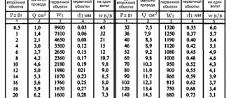
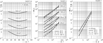
| Compared to conventional designs, toroidal transformers have a number of significant advantages. Despite their small size and weight, they have a significantly higher efficiency. Therefore, these devices are widely used in welding machines and voltage stabilizers. The correct calculation of a toroidal transformer in relation to specific operating conditions is of great importance. There are various calculation methods that provide results with varying degrees of accuracy. Most often, tables are used for calculations. Definition of basic parametersBefore starting calculations, it is necessary to determine the basic parameters of the transformer. First of all, this concerns the type of wires and the number of turns, on which the total length of the conductor depends. Next, you need to make the right choice of cross-section, which affects the output current and power of the device. One should also take into account the fact that with a small number of turns, the primary winding will heat up. Exactly the same situation arises when the power of consumers connected to the secondary winding exceeds the power supplied by the transformer. As a result of overheating, the reliability of the device decreases, and sometimes the transformer may ignite. As an example, a table is given that can be used to calculate a toroidal transformer operating at a network frequency of 50 Hz. The cores of the devices can be made of cold-rolled steel grades E310-330, with a thickness of 0.35 to 0.5 mm. Ordinary steel, grades E340-360, can also be used, where the thickness of the tape will be in the range from 0.05 to 0.1 mm. The symbols in the table correspond to:
When winding a toroidal coil, only external and interwinding insulation is used. Despite the even laying of the winding wires, the winding thickness along the inner diameter necessarily increases due to the difference between the outer and inner diameters of the core. Therefore, it is recommended to use conductors whose insulation has increased mechanical and electrical strength, for example, PELSHO and PESHO brands, and in some cases - PEV-2. For external and inter-winding insulation, cambric tape, LShSS varnished fabric, 0.06-0.12 mm thick, as well as triacetate or fluoroplastic film, 0.01-0.02 mm thick, are most often used. Formulas for calculating a toroidal transformerThe main parameters for calculating a toroidal transformer are the power supply voltage (Uc) equal to 220 V, the output voltage value (Un) - 24 V, current load (In) - 1.8 A. To determine the power of the secondary winding there is a formula: P = U n x I n = 24 x 1.8 = 43.2 W. Next, the overall power of the transformer device is determined by the formula: The efficiency value and other data necessary for calculations are selected from the table in the appropriate column and row for a specific overall power. The next step is to calculate the cross-sectional area of the core using the formula: The selection of core sizes is carried out as follows: The closest type of core with standard parameters will be OL50/80-40, with a cross-sectional area S = 60 mm2, which should be no less than the design one. The inner diameter of the core is determined in accordance with the condition that dc has a value greater than or equal to dc':
Now you need to determine the number of turns in the primary and secondary windings: Since magnetic flux dissipation in any toroid is very insignificant, the voltage drop in the windings can only be determined by their active resistance. As a result, the relative value of the voltage drop in the windings of a toroidal transformer will be much less than in conventional transformers. In this regard, losses in the resistance of the secondary winding are compensated by increasing the number of turns by approximately 3%. The calculation will look like this: W1-2=133 x 1.03=137 turns. The diameters of the winding wires can be determined by the formula: Here I1 is the primary winding current, determined by its own formula: Transformers manufactured according to calculations using the table have been successfully tested at a constant maximum load operating for several hours. Thus, the calculation of a toroidal transformer allows one to obtain accurate results confirmed in practice. Using this technique, you can determine the necessary parameters for any device. | ||||
| Efficiency | 0,76-0,88 | 0,88-0,92 | 0,92-0,95 | 0,95-0,96 |
3. The actual cross-section of the steel of the magnetic core at the location of the transformer coil;
4. The calculated cross-section of the magnetic core steel at the location of the transformer coil;
5. Actual cross-sectional area of the core window;
6. The value of the rated current of the primary winding;
Table No. 2.
Value Total power of secondary windings Pout, [W]2-15 15-50 50-150 150-300 300-1000
| COS Φ | 0,85-0,90 | 0,90-0,93 | 0,93-0,95 | 0,95-0,93 | 0,93-0,94 |
7. Calculation of the wire cross-section for each of the windings (for I1 and I2);
Table No. 3.
Magnetic circuit design Current density J, [A/mm sq.] at Pout, [W]2-15 15-50 50-150 150-300 300-1000
| Ring | 5-4,5 | 4,5-3,5 | 3,5 | 3,0 |
8. Calculation of the diameter of the wires in each winding without taking into account the thickness of the insulation;
9. Calculation of the number of turns in the transformer windings;
n is the winding number, U' is the voltage drop in the windings, expressed as a percentage of the nominal value, see table.
In toroidal transformers, the relative value of the total voltage drop in the windings is significantly less compared to armored transformers.
Table No. 4.
Tor, value U' Total power of secondary windings Pout, [W]8-25 25-60 60-125 125-250 250-600
| U'1 | 7 | 6 | 5 | 3.5 | 2.5 |
| U'2 | 7 | 6 | 5 | 3.5 | 2.5 |
Table No. 5.
Magnetic circuit design Magnetic induction Vmax, [T] at Pout, [W] 5-15 15-50 50-150 150-300 300-1000
| Thor | 1,7 | 1,7 | 1,7 | 1,65 | 1,6 |
10. Calculation of the number of turns per volt;
11. Formula for calculating the maximum power that the magnetic circuit can deliver;
Sst f – the actual cross-section of the steel of the existing magnetic circuit at the location of the coil;
Sok f – actual window area in the existing magnetic circuit;
Vmax - magnetic induction, see table No. 5;
J - current density, see table No. 3;
Kok - window fill factor, see table No. 6;
Kst is the coefficient of filling of the magnetic circuit with steel, see table No. 7;
Subtleties of calculation manipulations
Most often, the primary winding is powered from a conventional 220 V alternating voltage network. If the master needs two secondary windings so that each produces at least 12 V, then the cross-sectional area should be at least 0.23 square meters. mm. But this data is not enough to correctly calculate a toroidal transformer.
The master needs to divide 220 V by a certain amount of voltage in the secondary circuit. This way you can get a coefficient of 3.9, which will mean that the cross-section of the wire for the secondary winding should be similar to this indicator. But in order to determine the number of turns, you need to resort to a fairly simple formula: multiply the voltage of 220 V by a factor of 40, and the resulting figure should be divided by the cross-sectional area of the magnetic circuit.
It is also worth considering that the level of efficiency of the toroidal transformer and its service life depend on the correctness of the calculations. That is why it is better to double-check everything several times in order to avoid the most common mistakes.
What you need to know to assemble a welding machine with your own hands
Anyone familiar with the rules of electrical installation can easily make a simple welding machine on their own. But before getting down to business, it is necessary to calculate all the components of the device. The efficiency of the device when operating from a regular household single-phase network will depend on this.
Design and principle of operation of the simplest welding machines
To obtain a stable welding arc, which will allow you to weld metal of different thicknesses, currents in the range of 70 - 150 A are required.
If you use devices designed for a voltage of 220 V, then they must consume high power, in the range of 15 - 30 kW. Therefore, such installations will be cumbersome, and it will not be possible to work with them normally.
But at home it will simply be impossible to connect them; standard networks are not designed for such a load.
Therefore, the main task in the design and assembly of welding machines is to provide the required current while reducing power consumption. This is only possible when performing welding work with reduced voltage on the electrodes.
The simplest welding machine has the following design:
- A step-down transformer that reduces the voltage to the limits of 55 - 70 V and at the same time increases the current strength to the required parameters. Thanks to this, it is possible to reduce energy consumption to reasonable limits.
- Current is supplied from the transformer to the electrode and the workpiece using special welding cables. They are distinguished by a larger cross-section and reinforced insulation, allowing them to work with high currents.
- For welding, you will need electrodes installed in the holder. Thanks to the coating used, they simplify the ignition and maintenance of the electric arc, which becomes the source of thermal energy necessary for melting the metal.
Welding transformer
There are no complex devices in the design of such welding machines. But during design, it is necessary to calculate the basic parameters, otherwise connecting inappropriate equipment to the network will lead to its failure, short circuits on the line, or it will simply be impossible for them to cook.
Types of welding machines
There are several main types:
Welding transformer. A step-down transformer is used for the converter.
Welding transformer
Welding inverter. An inverter power supply with PWM serves as a converter here.
Welding rectifier. This is the same as a welding transformer, only it has a diode or thyristor rectifier in the secondary circuit.
Welding rectifier
Semi-automatic Welding is carried out in an inert environment; a gas cylinder is used for this.
Also read: How to make a phase indicator with your own hands
Simplified welder calculation diagram
In practice, calculations are made based on the type and diameter of the electrodes used. Yes, there are more complex and accurate calculation formulas, but they are rarely used by amateurs. To obtain a stable and productive arc, it is necessary to obtain a current with the following indicators:
- For electrodes with a diameter of 2 mm, 30 - 80 A is sufficient.
- When the diameter increases to 3 mm, the current should increase to 70 - 130 A.
- For 4 mm electrodes, the value is set to 110 - 170 A.
- 5-mm electrodes are cooked at a current of 150 - 200 A.
The difference in current values is due to working with metals of different thicknesses and physical properties.
When making a welding machine yourself, you most often have to be content with a magnetic core from other devices, which is available. Therefore, the simplest calculation will be performed based on these two known characteristics - the cross-section of the magnetic circuit and the required current strength on the secondary winding.
Please note that it is preferable to use rod-type cores to assemble the transformer. Compared to armored ones, they provide a higher current density in the windings and have increased efficiency.
Types of magnetic cores
In addition, the location of the windings on the arms of the core is also important. If the primary and secondary windings are separated into different rods, this will lead to increased magnetic dissipation due to the increased air gap. Therefore, it is considered preferable to place a part of both windings on both one and the other rod.
In this case, to determine the required number of turns of the primary winding, use the following formula:
N1 = 7440 × U1/(Sout × I2)
Where
N1 - estimated number of turns;
U1 - mains voltage (200-240V);
Siz is the cross-section of the existing magnetic circuit;
I2 is the required welding current.
Please note that for devices with spaced windings, a different formula is used:
N1 = 4960 × U1/(Sout × I2)
If you have to carry out work under conditions of unstable voltage in the network, it makes sense to calculate the number of turns for the main values - 180, 190, 200, 220 and 240 V. When winding the wires, simply make taps at these values, which will allow you to select a stable operating mode for the transformer in any conditions.
The required number of turns of the secondary winding is calculated using the following simplified formula:
N2 = 0.95 × N1 × U2/U1
Where
N1 - estimated number of turns;
U1 - mains voltage (200-240V);
U2 - required no-load voltage on the secondary winding (50 - 70 V).
Also read: How to make a phase indicator with your own hands
For the primary winding, choose an insulated copper wire with a cross-section in the range of 5 - 7 square meters. mm, it is enough to work with a household single-phase electrical network. When choosing, pay attention to the heat-resistant properties of the insulation; it must withstand significant heat, which cannot be avoided.
The secondary winding is wound with a thicker wire, which is associated with a significant current strength that will flow through it. The best option would be a copper bus with a cross-section of at least 30 square meters. mm.
Welding transformer - the simplest type of equipment
To perform most welding work at home, a step-down welding transformer is sufficient without additional circuits or devices. The assembly sequence of such a unit is as follows:
- Divide the total number of turns of each winding into two equal halves to place them on both core bars.
- If you assemble a core from individual plates, you will need to fix them with ties or in a simple cage. The plates should not be isolated from each other.
- For the coils, a frame is made of thick electrical cardboard. The internal size must correspond to the cross-section of the core and must allow the coil to be moved up or down.
- The windings are wound by laying the turns close to each other. If necessary, make several rows of laid wire.
- If the primary winding is designed with taps, then a loop is made on the required number of turns and brought out without cutting it.
- The primary winding is placed on the lower part of the core, the secondary winding is attached to the top.
- To change the current strength for welding metals or when working with parts that differ in thickness, a simple regulator is provided. It will move the secondary winding coils up and down.
- The operating principle of such a regulator is based on changing the air gap between the windings. As a result, the parameters of the magnetic field change, which leads to an increase or decrease in the current strength in the secondary winding.
- The regulator is a threaded screw, which, when tightened, raises the coils. To do this, these elements are connected to each other.
In almost all cases, homemade welding equipment is made without a housing. This is done to prevent overheating of the coils, which can cause the device to fail.
If you make a circuit with forced cooling using a fan, then the welding transformer can be installed in the housing.
For its manufacture, temperature-resistant, fireproof materials are chosen, for example, textolite with a thickness of 1.5 - 2 cm.
Studs are placed on the surface of the housing for connecting welding cables and network wires. The ability to connect to the taps of the primary winding is ensured by arranging separate contacts or installing a powerful packet switch to the required number of positions.
Also read: How to make a phase indicator with your own hands
Welding rectifier - features of operation and assembly
To perform certain types of welding work, for example, with stainless steel, the use of alternating current supplied by a transformer is not used. To work with such metals, a constant voltage supply is required. In addition, direct current cutting reduces the consumption of electrodes, and metal spattering is prevented during welding.
To perform work in such conditions, welding rectifiers are used, which allow welding with direct and reverse polarity current. If you have experience in installing electronic circuits, then you can also assemble such a device yourself.
The basis of the welding rectifier will be the same step-down transformer. The difference lies in the presence of a rectifying electronic circuit. If desired, you can remake the already described welding transformer or assemble a universal device that will allow you to weld with both alternating and direct current.
https://www.youtube.com/watch?v=hi6X6T8iVrs
The simplest diagram of the electronic part of a welding rectifier looks like this:
Schematic diagram of a welding rectifier
When assembling such devices, the following design features should be taken into account:
- The main part of the device is a rectifier bridge made of powerful power diodes. They are connected according to the diagram, taking into account polarity.
- Smoothing of current ripple is carried out due to a filter made on the capacitor and choke coil. Please note that the components must have a margin of 2.5 - 3 permissible voltage.
- When working with high currents, the elements heat up. Semiconductor diodes are sensitive to overheating. Therefore, they are installed on radiators, which will increase the intensity of heat removal.
- When enclosing the device in a housing, it becomes mandatory to use a fan to increase cooling efficiency.
We pay attention to the connection of individual elements of the circuit. Considering that they will be exposed to high current, it is necessary to ensure reliable contact. If this is not done, then the wires in these areas will heat up and burn out. The preferred option is with fastening using platforms with a bolt and nut.
The choke in such designs is made in the form of a separate remote inductor, which is connected as needed. Note that installing a rectifier does not prevent the welding current from changing using the secondary winding coil position regulator.
As you can see, there are no difficulties in assembling a welding machine yourself. But it’s worth working on such devices only if you have experience in designing simple devices that operate with lower currents. Otherwise, entrust the assembly to a specialist or buy a factory welding machine.
Microwave welding machine:
AC assembly example
Click on the first photo and see the assembly sequence: