In electrical engineering, the term “polarity” is often used. Polarity is the state of a system or body in which different points have opposite physical properties. The best known examples of polarity are opposite electric charges and magnetic poles. When it comes to electric current, one of the poles is called positive (it has fewer electrons), and the other is called negative (it has more electrons). If these two poles are connected with a wire, electrons will begin to move from the negative pole to the positive pole. This is electric current. Today we’ll talk about how to determine plus and minus with a multimeter.
Setting up the multimeter
First, you need to set up the multimeter to work.
Probe connectors
Multimeters have 3 to 4 probe connectors. In 90% of measurements, only two connectors will be needed. These are COM and VΩ.
The black probe of the multimeter is always connected to COM. The default black probe is negative, the common wire. That's why it's called COM.
To measure voltage, resistance or continuity of radio components, the red probe is connected to the VΩ connector.
Where is the plus on the millimeter?
By default, the positive wire is the red wire if you have it connected correctly. The black probe of a multimeter is always a minus, and it is inserted into the COM connector regardless of the operating mode.
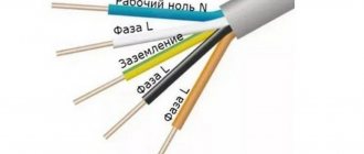
Colors for 220V and 380V networks
Installation of single- and three-phase electrical networks is facilitated if the wiring is made with multi-color wire. Previously, a flat two-core white wire was used for single-phase residential wiring. During installation and repair, to eliminate errors, it was necessary to ring each core individually.
The production of cable products with colored cores in different colors reduces the labor intensity of the work. To indicate phase and zero in single-phase wiring, it is customary to use the following colors:
- red, brown or black – phase wire;
- other colors (preferably blue) – neutral wire.
The phase markings in a three-phase network are slightly different:
- red (brown) – 1 phase;
- black – 2 phase;
- gray (white) – 3 phase;
- blue (cyan) – working zero (neutral)
- yellow-green – grounding.
Domestic cable products comply with the standard for core coloring, so a multiphase cable contains differently colored cores, where the phase is white, red and black, the neutral is blue, and the ground is yellow-green conductors.
When servicing networks installed according to modern standards, it is possible to accurately determine the purpose of the wires in the junction boxes. If there is a bundle of multi-colored wires, the brown one will definitely be phase. The neutral wire in distribution boxes has no branches or breaks. The exception is branches to multi-pole switching devices with complete circuit breaking.
Checking work
Dial icon
Make sure you have connected the probes correctly.
We check the reliability of the connection. To do this, switch the multimeter to diode continuity mode. In this mode, the voltage drop across the probes is measured.
If you close the probes, the device will show zero.
Probe short circuit (zero)
The unit denotes infinity, that is, a break in the circuit or the limit of measurement.
Measurement limit (or break)
Rules for using a multimeter
First you need to familiarize yourself with the technical data sheet of the device, study its capabilities and measurement limits.
When taking measurements, do not touch the metal base of the probes. If you check the details, this may affect the readings, they will be false. And when testing high voltages, if you touch the metal base of the probes, you can get an electric shock.
Voltage measurement
When measuring voltages, do not touch the metal base of the probes.
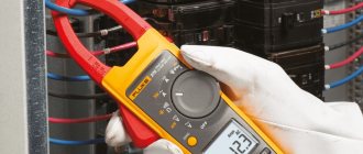
AC voltage measurement
To measure the alternating voltage in the outlet, move the switch to the V~ icon at 750 V.
The multimeter is set to measure AC voltage
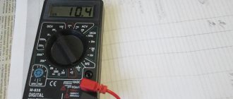
If you do not know the approximate values of the voltage source, then you should always set the measuring limit of the device to the maximum.
Do not touch the metal base of the probes. Is it dangerous. As you can see, in the photo the multimeter shows 222 V.
Checking the mains voltage with a multimeter
And that is why the limit of 750 V was chosen. If you set it less, the device will show infinity and may fail.
DC voltage measurement
To measure DC voltage, you need to switch the device to the V— icon.
The multimeter is set to measure DC voltage
Since the example above measures an 18650 battery, its maximum value certainly cannot be higher than 5 V. Therefore, you can safely set it to 20 V if you are confident in the source and in your assumptions.
If, when measuring DC voltage, you see a minus sign in front of the number (-), this means that the polarity of the source is reversed.
Battery voltage measurement
That is, the black probe, which is negative by default, is connected to the battery positive. And on the red probe, accordingly, there is a minus of the source. Thanks to this, you can find out the polarity of an unknown source.
Correct polarity of the device and battery
We swap the probes on the battery to the opposite, and now we know exactly where the positive is on the battery and where the negative is. This is a very useful feature of a digital multimeter. Compared to analog, it is not damaged if the probes are swapped in places, and you can accurately determine where the plus and minus of the voltage source are.
Ground wire color
By modern standards, the ground conductor is yellow-green. It usually looks like yellow insulation with one or two longitudinal bright green stripes. But there are also transverse yellow-green stripes in color.
Grounding may be this color
In some cases, the cable may only have yellow or bright green conductors. In this case, the “earth” has exactly this color. It is displayed in the same colors on diagrams - most often bright green, but it can also be yellow. Signed on circuit diagrams or on ground equipment in Latin (English) letters PE. The contacts to which the “ground” wire must be connected are also marked.
Sometimes professionals call the grounding wire “neutral protective”, but do not be confused. This is an earthen one, and it is protective because it reduces the risk of electric shock.
Checking radio components with a multimeter
Using a multimeter you can test almost any part.
Diode check
To check if the LED is working properly, connect the black probe to the cathode and the red probe to the anode.
Checking LED operation with a multimeter
If the LED is small, it will light up. The crown voltage is enough to ignite small parts.
Measuring SMD diode on board
When checking the pn junction of diodes using a continuity test, the screen does not show resistance, but rather the voltage drop.
Measuring the resistance of parts
Switch the device to the scale with the Ω sign. This is a resistance measurement.
Resistance measurement
The dot shows the limit of the selected measurement. In the photo, the limit is 20 kOhm (not 200 kOhm, as shown above).
Checking the Resistor Resistance
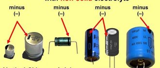
Checking capacitors
For example, to measure capacitance, you must first switch the red probe to another connector, where the capacitor is indicated.
Switch the device to a scale with farads.
Capacitance measurement
When measuring capacitances, the red probe should be on the positive side and the black one on the negative side. And before measuring electrolytic capacitors, they must first be discharged, otherwise the measuring circuits can be damaged.
Measuring capacitance with a multimeter
Wire marking
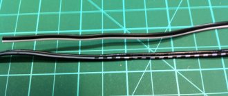
Wire marking is the application of a specific mark to their outer surface to indicate the required characteristics. Marking can be in the form of color markings, inscriptions (numbers and letters), labels or tags.
Important! Letter or numerical markings indicate the material of the shell and cores, cross-sectional area, number of cores inside and other parameters. The red wire indicates the positive phase or plus
You can remember it by the name “Red Cross”. Black corresponds to negative phase
The red wire indicates the positive phase or plus. You can remember it by the name “Red Cross”. Black corresponds to the negative phase.
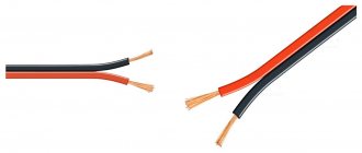
But this designation does not always work: the colors may be different, for example, green and blue, or absent altogether. There are many more colors in three-phase wires:
- The phase is indicated by red, orange, purple or gray colors:
- Neutral - blue or white-blue;
- Grounding - stripes of green or yellow colors.
To avoid mistakes during installation, if in doubt, it is better to check the polarity in advance.
Other Multimeter Features
You can also measure direct and alternating current. The symbols on the switch scale are the same as for voltage. Alternating current is A~, direct current is A—.
To do this, switch the red probe to the socket where mA is written. If you need to measure more currents, that is, amperes, then the red probe switches to the connector where the amperes are indicated.
When inscriptions such as “20 A MAX 10 SEC” are present, this means that currents of no more than 20 A can be measured for no longer than 10 seconds. Otherwise the fuse will blow.
All other functions of the multimeter depend on its functions, cost and manufacturer. You can measure the frequency of current, h21e of transistors, capacitance of capacitors, etc.
Refinement of multimeter probes
The needles at the ends of the probes are very practical. They allow you to measure SMD parts. It is enough to solder ordinary needles to the ends of the multimeter. You can also make a couple of probes with crocodiles so that you can attach the probes to the wires or parts being measured.
Description of poles
In the case of an electric current passing between two points, or poles, one of the poles will have more electrons than the other. The pole with more electrons is said to have a negative charge. The pole with fewer electrons has a positive charge. When two poles are connected by a wire, electrons move from the negative pole to the positive pole. This flow is called electric current.
Polarity can be of different types
For your information! In a DC circuit, one pole is always negative and the other positive with electrons flowing in only one direction. In an alternating current (AC) circuit, the two poles alternate between negative and positive poles with the electrons flowing in the opposite direction.
Bottom line
A multimeter is an excellent measuring device. In fact, it is inferior to specialized devices such as ESR devices, oscilloscopes, frequency counters, etc. If you are a beginner radio amateur, then it is best to buy the simplest and most common multimeter, such as the DT 838. It will be enough for any work. More advanced versions have convenient stands and display backlighting.
Of course, you can buy a more advanced one, with measuring the capacitance of capacitors, but the scale and accuracy compared to specialized instruments will be very low. Still, a multimeter is needed for quickly and efficiently measuring voltages and checking radio components. There is no need to demand high accuracy and rich functionality from a multimeter.