As the name suggests, a multimeter is used to measure several electrical quantities. A multifunctional device combines a voltmeter, ammeter, ohmmeter, continuity test, and may also have additional functions such as a thermocouple or low-frequency generator, testing capacitors and transistors.
Analog testers with a scale and pointer are almost never found, as they have long been supplanted by affordable digital instruments. The latter, in addition to the accuracy and number of modes, differ in the type of determination of quantities. Automatic ones show the result immediately after selecting the mode; in manual ones, you need to additionally set the measurement range.
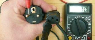
All multimeters have a similar design. There is a screen on the front panel, under it there is a rotary mode switch, and just below there are connectors for connecting probes. Some models have buttons to turn on the backlight, remember readings, and for other additional functions.
Wires with probes that need to touch the part when measuring are connected to the corresponding connectors. The black wire is always to the socket marked COM, and the red wire, depending on the current value. If it does not exceed 200 mA, then to the VΩmA connector, if it exceeds, then to 10ADC (10A MAX). Such high currents are not encountered in everyday life, so the VΩmA socket is mainly used.
The numbers on the scale indicate the maximum value that can be tested within that range. For example, in DCV 20 mode, DC voltage is measured from 0 to 20 V. If it is 21 V, then you need to switch one step higher, to position 200. It is important to select the range in accordance with what is being measured, otherwise the multimeter will be damaged.
Expert opinion
It-Technology, Electrical power and electronics specialist
Ask questions to the “Specialist for modernization of energy generation systems”
How to measure voltage, current, resistance with a multimeter, check diodes and transistors » Website for electricians - articles, tips, examples, diagrams So don’t be surprised if the multimeter doesn’t want to measure current at these limits, but immediately remove the back cover and look at the fuse. Ask, I'm in touch!
How to measure DC voltage with a multimeter
Switch to constant voltage mode. It is usually denoted by the symbols V with a straight line and a dotted line, or DCV.
In multimeters with manual range selection, additionally set the approximate measurement value, or preferably one step higher. If you are not sure, start with the maximum and gradually lower.
Touch the probes to the contacts and look at the screen. If a minus sign is displayed along with the number, it means that the polarity is reversed: the red probe touches the minus, and the black probe touches the plus.
In a hand-held multimeter, you may have to adjust the measuring range.
If the display shows a unit, you need to increase the measurement limit; if it is zero, the OL or OVER symbols need to be lowered.
What kind of lighting do you prefer?
Built-in Chandelier
What is wire insulation resistance
Insulation resistance is one of the most important parameters of any cables and conductors. This is based on the fact that all wires are subject to external influences during their operation. In addition to external influence, there are also internal ones: the influence of the cores of one wire on each other, interaction through electromagnetic fields. All this, one way or another, leads to leaks.
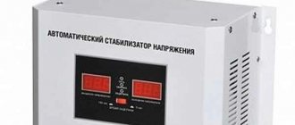
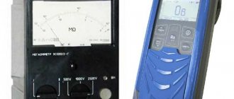
Industrial megger for measuring large resistance values
That is why any electrical and non-electrical wires are created with insulation that protects the conductor from external influences. Popular insulating materials include rubber, polyvinyl chloride, oil, wood and paper. These materials are used based on the purpose of the cable. For example, wires buried underground are insulated with relatively thick dielectric tape, while telecommunications cables may be enclosed in a simple aluminum foil wrapper.
Old Soviet analog bench ohmmeter
Important! Insulation is the protection of cores from exposure to otherworldly factors, protection of cores from each other, from short circuits and from various leaks. Insulation resistance is the amount of resistance between the conductors of a wire or between one of the conductors and the insulating layer.
Any material ages and deteriorates over time, which leads to deterioration of its characteristics and a decrease in insulation resistance to direct or alternating current. The insulation resistance characteristic is indicated on the cable and is standardized in its GOST. It is determined in laboratory conditions at a temperature of 20 degrees.
Carrying out resistance measurements with a professional megohmmeter
Low-frequency communication cables have a minimum insulation resistance of 5 Gigaohms per kilometer, and coaxial cables, in turn, have a minimum insulation resistance of 10 Gigaohms per kilometer. Measurement and testing of resistance is carried out on a regular basis with a megohmmeter: at mobile communication installations - once every 6 months, at high-risk facilities - once every 12 months, at other facilities - once every three years.
You might be interested in this Features of the instrumentation and automation profession
Resistor to increase the resistance of the electrical network
Features of measuring currents with a multimeter
To measure “high” currents, you will have to switch the red probe into the socket labeled 10A. A warning notice can be seen near this socket stating that this limit is not protected by a fuse and measurements can only be taken for 10 seconds, after which a break of 15 minutes can be taken.
Those who have used pointer testers know that before starting to measure resistance, you need to set the pointer to scale zero. To do this, simply connect the measuring probes and turn the corresponding knob.
Although digital multimeters do not need to be set to zero, you still have to connect the probes: this is another good rule for using the device. Thus, first of all, the integrity of the probes is checked (standard probes break very often), and at the same time the scale zero. If the multimeter is in the “dial” mode (as shown in the figure), a beep will sound.
A sound signal is heard only if the resistance between the measuring probes does not exceed 47...50Ω. This property is used when checking the integrity of conductors and tracks on printed circuit boards. The mode for testing semiconductors is also combined with the wire testing mode.
If the input probes are not shorted, or there is an open circuit in the circuit under test, or the diode being tested is switched on in reverse polarity, 1 is displayed on the multimeter display:
The same thing can be seen on the display if you try to measure a resistance of 200KOhm at the limit of 200Ohm. In other words, the measured resistance is higher than the measurement limit, the device “thinks” that the circuit is open.
The same picture will happen if the 24V voltage is measured in the range of 20 - the device is off scale. Just don’t apply a voltage of 100...200 volts to range 20, since the device may not withstand such abuse and will simply burn out.
Expert opinion
It-Technology, Electrical power and electronics specialist
Ask questions to the “Specialist for modernization of energy generation systems”
How to use a multimeter correctly - Lifehacker The wires in the measuring probes are attached only by soldering, and when they come out of the plastic tips they dangle and dangle freely, and over time they unwind completely and fly out. Ask, I'm in touch!
What is current and why measure it?
This is the amount of electricity (charge or number of electrons) that moves through the cross section of a conductor in one second. In formulas it is denoted by the capital Latin letter I. The unit of current is Amperes (A).
Current strength is often referred to simply as current. It comes in two types:
- Constant. The current does not change in direction or magnitude. That is, this is a uniform directed movement of charged particles. Formula for calculation: I=Δq/Δt ( Δq(C) is the charge in Coulombs that passed through the cross section; Δt(c) is the time during which the charge passed).
- Variable. This is a current in which even one characteristic changes. It differs at different points in time. To calculate such a current, it is better to use the derivative.
It is generally accepted that a current of 1 A is generated in a conductor with a resistance of 1 ohm if there is a voltage of 1 V.
Checking the current with a multimeter is needed for:
- Clarification of the actual power consumption of the electrical unit.
- Detecting defects in electrical devices if its power is less than that declared by the manufacturer.
- Determination of the electrical capacity of autonomous energy sources, for example, batteries.
- Detection of current leakage in electrical circuits.
Ammeters are often used to determine current or amperage. But, if you have a multimeter with this function, feel free to use it.
Here's a video on how to measure current with a multimeter:
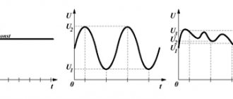
We measure alternating voltage.
The process of measuring alternating voltage is similar to measuring direct voltage with the only difference that there is no need to determine where “ plus”
" and "
minus
". As an example, let’s measure the voltage of a household electrical network of 220 Volts.
Attention! Be especially careful and extremely careful when measuring high voltages. Do not touch the metal parts of the probes.
This sector is divided into only two subranges with measurement limits:
indicating the maximum value of the subrange within which the measurement is carried out. The measuring leads are the same as when measuring DC voltage.
Selecting the measurement limit 750
Volt.
Additionally, we make sure that the insulation of the wires and probes of the multimeter is in good condition. Once again we check the correctness of the selected measurement limit, and only after that we measure the 220 Volt network voltage
.
As you can see, everything is very simple. And here we also do not forget that when measuring an alternating voltage, the value of which is unknown, to determine it, we start only from the maximum limit
, namely with
750
Volts.
After finishing work with the multimeter, be sure to turn it off by moving the switch to the “ OFF”
“, otherwise you won’t have enough batteries.
To finally understand how to measure voltage with a multimeter, watch this video.
How to measure current
,
resistance
, how to use
a continuity tester
and
a sound generator
, read in the second part of the article how to use a multimeter for beginners. Good luck!
Expert opinion
It-Technology, Electrical power and electronics specialist
Ask questions to the “Specialist for modernization of energy generation systems”
How to measure DC voltage with a multimeter A multifunctional device combines a voltmeter, ammeter, ohmmeter, continuity test, and may also have additional functions such as a thermocouple or low-frequency generator, testing capacitors and transistors. Ask, I'm in touch!
Measurement of small resistances, shunts
In this article we will try to learn how to measure small resistances. Radio amateurs sometimes have a need to accurately determine the resistance of a shunt when making or repairing an ammeter, so that it, in turn, also accurately displays its units of measurement or for other purposes. But how to do this when the multimeter does not have a milli-ohm scale, the markings are either absent or completely unknown and incomprehensible? Most measuring instruments have a minimum scale of 200 Ohms for measuring resistance and 3.5 - 4 digits, when you short-circuit the probes there is already about 0.7 Ohms, when measuring resistance 0.1 Ohms nothing changes, trouble. Let's fix it now.
I suggest using a bridge measurement circuit for this purpose. Everyone should understand what a bridge is; we won’t dwell on that. Let's make a bridge of resistors, apply some voltage to it and measure it, although we can also measure the current, it won't make a difference; we choose what is more accurate at hand. So what does low resistance measurement have to do with it? Patience, everything is in order from afar. There is such a wonderful thing as bridge balance. The product of the resistances of the opposite arms of the bridge, provided it is balanced, will be the same. And voltages and currents, when the bridge is balanced, will cancel each other out and give a total of 0.
(Let R0 be R3 and Rx be R4)
or
So, based on the above, if instead of one of the resistors we put our small resistance of an arbitrary value in the bridge, and make the other resistor variable or tuning (according to the diagram, we use two variable resistors to accurately balance the bridge, especially in the case when there are no multi-turn variables at hand resistors) to achieve bridge balance. This circuit can be used to measure shunts and small resistances:
It was lazy to assemble the circuit, especially since it takes a lot of time to make the board, so an experimental sample of the circuit was made by hanging installation. Here, resistors R1 and R2 are not 1%, but they were selected as close as possible to the resistance of a given value, the resistance error did not exceed 0.5% at room conditions.
But you need to know how to get the exact value of the measured resistance. Firstly, the main feature of such a circuit is that it “multiplies” the measured resistance. This means that there is no need for a milli-ohm scale in a multimeter. A resistance of 0.1 Ohm can already be measured on a kilo Ohm scale. Only the measurement will now be not direct, but indirect; you will have to use a little mathematics and calculate the final result of the measurement.
Let's decide what range of ratings we will measure (meaning low resistance or shunt resistance). To do this, you need to select the values of the variable resistors:
According to the circuit, we use two variable resistors for greater interaction accuracy, 1 kOhm and 100 Ohm. This resistance of variable resistors will allow you to measure the maximum resistance of 1.1 ohms, the minimum while maintaining measurement accuracy of 0.01 ohms (with Rx = 0.01 ohms R0 should be 10 ohms, which also need to be measured quite accurately with your multimeter)
And the values of constant resistors, so that the bridge can be easily balanced and it is convenient to calculate the value of the shunt or small resistance:
The multiplicity of resistors relative to each other is best taken exactly like this - 10, 100, 1000, in order to quickly calculate the final result, although no one forbids taking non-round numbers, so that later
What is a multimeter
A multimeter or multitester is a compact, ergonomic and multifunctional device for measuring the basic parameters of an electrical network for any purpose. All multimeters allow you to measure current, voltage, resistance and even temperature with a certain accuracy using their probes.
Appearance of a typical dielectric plastic digital multimeter
There are two types of multimeters:
- Analogue, which display measurement results using mechanical display tools: arrows, bars and division values, showing the quantitative characteristics of the measured value;
- Digital. The most commonly used types of devices, the information is displayed through a built-in display, and all data is calculated digitally.
You might be interested in Features of pliers and pliers
Megaohmmeter GM3123 for use in industrial high voltage networks