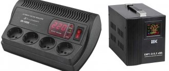
The question of how to check a voltage stabilizer is relevant for many enterprises, organizations and private users. Stabilizing devices are quite complex equipment, the quality of which determines the serviceability of the connected expensive equipment. Therefore, monitoring their performance and timely detection of faults is a necessary condition for ensuring uninterrupted technological processes and minimizing additional costs.
Stabilizer malfunctions
The most important characteristics of stabilizers that are subject to control are the rated input and output voltage, load current, degree of stabilization, ripple value, and temperature of internal components. To fully diagnose these parameters, special equipment is required. Testing devices using triac switches is considered especially difficult. It requires precise circuitry and specialized measuring instruments, including an oscilloscope.
Let's look at some common problems with stabilizers:
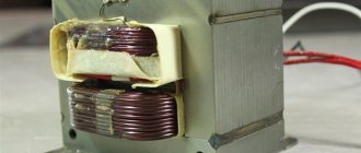
- In relay devices, most often the relays that are responsible for switching the transformer windings fail. Also sometimes the coil burns out.
- The transformer overheats without a serious load. This problem occurs due to turn-to-turn short circuit or short circuit in the switches.
- Overheating of the servo stabilizer. It can occur due to the short circuit of adjacent turns due to contamination of the contact pads. To prevent this, devices must be periodically disassembled and cleaned.
- Burnout of one of the electronic components. It can occur due to short circuits, overloads, or excessively high temperatures.
Is it possible to check the zener diode without desoldering?
Yes, this is possible, but not all modes of the radio element are tested. The zener diode always has electrical connections with the rest of the circuit elements, so it is impossible to check it for breakdown as part of the product.
You can check the zener diode with a multimeter on the board only for the stability of the supply voltage. To do this, you need to turn on the electrical device and connect the tester probes to the legs of the part.
Naturally, you should know the original value from the labeling. In this case, it is necessary to measure the voltage at the input and after the stabilizer. If the value at the input is higher than or equal to the voltage after the zener diode, then it is working.
How to check the electrical stabilizer?
To troubleshoot the device, you need to do the following:
- Preliminary check. It can be carried out without special devices. To do this, you will need two table lamps of the same power, an electric stove or other powerful consumer, and a power extension cord with several sockets. We connect a stabilizer, one light bulb and an electric stove to the extension cord. We power the second light bulb from the stabilizer. Turn on the tile. If the stabilizer works correctly, then the light of the lamp connected to it will not change, but the light of the lamp connected to the extension cord will decrease.
- Disassembling the equipment, thoroughly removing all contaminants, cleaning the contact pads to a metallic shine.
- Inspection of the stabilizer, identification of electronic components with traces of exposure to high temperature. Overheated resistors look charred, and blackening and cracks may appear on the transistors. You also need to pay attention to swollen capacitors. Another symptom of overheating is a change in the shade of the textolite board.
- Ringing of power switches and other components.
How to check the zener diode with a multimeter for serviceability?
The technique is similar to the classic diode. We set the switch to the diode test position (present on any device) and connect the probes to the contacts of the part. A direct connection shows the flow of current, a reverse connection shows the closed state of the pn junction.
This test only indicates that the element is not “broken.” It will not be possible to measure parameters this way.
How to check the zener diode with a tester for proper response voltage?
First you need to find out how many volts the zener diode is. How to do it? By marking. Depending on the type of case, this may be a symbol or color designation. Marking tables are in reference books; we will not dwell on this issue in detail.
We assemble a simple circuit with a ballast resistor (to limit the current, since there is no load provided).
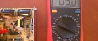
Checking a linear DC voltage regulator using a multimeter
One of the main components of a linear DC voltage regulator is a Zener diode or Zener diode. Failure of this particular element is the most common cause of device failure. Before you figure out how to test a voltage stabilizer with a multimeter, you need to understand the principle of operation of a zener diode. In operating condition, it passes current strictly in one direction. As the input voltage increases, the amount of electric current passing through the zener diode increases sharply. The element begins to operate in breakdown mode, ensuring that the output voltage is maintained with a given accuracy. Excessive currents lead to overheating and damage to the zener diode.
To check the component, connect the positive probe of the multimeter in resistance measurement mode to the cathode terminal, and the negative probe to the anode terminal. The device must show a certain resistance value. After this, we swap the probes. Resistance must become endless. Such multimeter readings indicate the serviceability of the zener diode. If during both measurements the device showed infinite resistance, the element broke. In the case when the resistance at different positions of the probes is zero, we can conclude that the zener diode has broken down.
Checking voltage stabilizer 17-33G
The 3.3 V stabilizer has a different pinout, as the reference information tells us. Thus, the left pin is the power negative or ground ( gnd ), the center pin is the positive output voltage ( output ), and the right pin is the positive input voltage ( input ). The maximum input voltage is 20V, so my power supply is suitable for testing this component.
Having connected the stabilizer according to the pin markings and checking the output voltage, I got a value of 3.28 V. This stabilizer is also working.
Lately, I have not published articles about device repair, since for the most part I repair the same devices; the repairs are typical and, for the most part, have been described by me previously. Therefore, I decided to dilute the content with such informative articles. I hope the article was useful =)
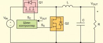
Checking according to the stabilizer circuit
The above method is not suitable for bi-directional and precision zener diodes. How to check the voltage stabilizer in this case? It is necessary to include the electronic components being tested in the circuit and apply voltage from the power source. To do this, you need a divider, which consists of one or more resistors. The resistor must ensure breakdown of the zener diode when voltage is applied from the power source.
Check procedure:
- The positive wire from the power supply is connected to the first terminal of the divider.
- The cathode terminal of the zener diode is connected to the second terminal of the divider.
- The anode terminal of the zener diode is connected to the negative terminal of the power supply.
- A multimeter in voltmeter mode is included in the circuit. The positive terminal is connected to the second terminal of the resistor, and the negative terminal is connected to the common power bus (negative terminal of the power supply).
- If a voltage equal to or greater than the stabilization voltage is applied to the first terminal of the divider, then at the output it should not exceed this value. This indicates a working zener diode. If the element is broken or incorrectly connected, the voltmeter will show zero. In the case of a broken zener diode, the multimeter readings will exceed the stabilization voltage.
Precision and double-sided devices
Precision zener diodes are tested in a similar way. Double-sided zener diodes are connected to the terminals of the power source without observing polarity.
To check the stabilizer, you need to switch the multimeter to DC measurement mode, observing the polarity. Initially, the amount of power supplied to the stabilizer is checked .
If the voltage is normal, then the multimeter is directly connected to the output of the stabilizer, measuring the voltage value at the output.
Tester for zener diodes
Checking zener diodes with a multimeter does not provide a 100% guarantee of their serviceability. This is due to the fact that it cannot check its basic parameters. Therefore, many radio amateurs make a zener diode tester with their own hands.
The circuit of the simplest version consists of a set of batteries, a fixed resistor with a nominal value of 200 Ohms, a variable resistance of 2 kOhms and a multimeter.
The batteries are connected in series to obtain the potential necessary for measuring the parameters of the zener diodes. Stabilization voltages generally lie in the range of 1.8-16 V.
Therefore, an 18 V battery is assembled. Then, to its terminals, we connect in parallel a series chain of a 2 kOhm variable resistor with a power of 5 W and a constant 200 Ohm resistor.
The second will play the role of limiting resistance. The leads of the variable resistor are connected to a three-pin terminal block.
The first contact is connected to the terminal connected to the positive of the battery, the second is the other extreme terminal, and the third is the middle movable contact of the resistor.
In other versions of testers, switching power supplies with adjustable voltage of the output stage can be used, but the essence does not change; the meter remains a multimeter.
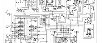
Diagram of a device for testing zener diodes
As you can see, the scheme is simple. The voltage from the transformer with two 24V secondary windings is rectified and filtered to obtain a constant voltage of about 80V, then goes to a voltage stabilizer formed by the elements (R1, R2, D1, D2 and Q1), which reduces the voltage to 52V to avoid exceeding the maximum operating voltage limit of the LM317AHV .
Pay attention to the letter index of the microcircuit. For LM317AHV, the input voltage, unlike LM317T , can reach a maximum of 57V.
Checking the stabilizer chip
It is required to assemble stabilizing circuits to power the device on the PIC 16F 628 microcontroller, which normally operates from 5 V. To do this, we take the PJ 7805 microcircuit, and on its basis we carry out the assembly according to the diagram from the datasheet. Voltage is applied, and the output is 4.9 V. This is enough, but stubbornness takes over.
We took out a box with integral stabilizers, and we will measure their parameters. To avoid making mistakes, we put the diagram in front of us. But when checking the microcircuit, it turned out that the output is only 4.86 V. Here we need some kind of probe, which is what we’ll do.
Diagram of the simplest method for checking zener diode voltage
Radio amateurs and all those who are good friends with electronics know that the task of finding a zener diode with the required characteristics (operating voltage) is boring and painstaking. It happens that you need to go through a lot of different instances until you find the desired Vz value. Checking the status of the zener diode is usually done using a regular multimeter diode scale, this test gives us an accurate idea of the condition of the component, but does not allow us to determine the Vz value. In general, a zener diode tester is a really convenient device when we want to quickly find out the value of the voltage Vz.
Checking the functionality of the L7805CV
How to check the functionality of the microcircuit? To begin with, you can simply ring the terminals with a multimeter; if in at least one case a short is observed, then this clearly indicates a malfunction of the element. If you have a power source of 7 V or higher, you can assemble a circuit according to the datasheet given above and apply power to the input; at the output, use a multimeter to record the voltage at 5 V, so the element is absolutely operational. The third method is more labor-intensive if you do not have a power source. However, in this case, you will also receive a 5 V power supply in parallel. It is necessary to assemble a circuit with a rectifier bridge according to the figure presented below.
To check, you need a step-down transformer with a transformation ratio of 18 - 20 and a rectifier bridge, a further standard kit, two capacitors for the stabilizer and that’s it, the 5 V power supply is ready. The capacitor values here are overestimated in relation to the L7805 connection diagram in the datasheet, this is due to the fact that it is better to smooth out voltage ripples after the rectifier bridge. For safer operation, it is advisable to add an indication to visualize the device being turned on. Then the diagram will look like this:
If there are a lot of capacitors or any other capacitive load on the load, you can protect the stabilizer with a reverse diode to prevent the element from burning out when the capacitors are discharged.
The big advantage of the microcircuit is its fairly lightweight design and ease of use, if you need power of one value. Circuits sensitive to voltage values must be equipped with such stabilizers to protect elements sensitive to voltage surges.