Types of cables for connection
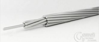
The most common cable for home electrical wiring is a PVA connecting cable, consisting of two insulating layers. Copper strands, stranded, twisted along the central axis. The wire is flexible, making it great for a variety of connections.
The voltage of connected devices must be up to 380 Volts.
The cross section is selected depending on the load:
- for a current of 6 A, PVA with a cross section of 0.75 mm is used;
- for 10 Amperes - the cross-section is 1 mm;
- for currents of 16 A – 1.5 mm.
In addition to the PVS wire, for connection there are multi-core cables ShVVP, PUGNP, PRS, KG. They are used less frequently for home wiring than PVS.
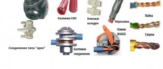
How to connect wires using clamps - nut or bolt type
The most common way to connect wires is with a Walnut clamp. This clamp received this name because of its external resemblance to a nut. They are produced in different sizes for connecting both thin and thick wires.
The inside of the “Nut” consists of two main and one intermediate metal plates. There are 4 screws along the edges of the plates. The plates themselves are placed in an insulated carbolite housing, consisting of two parts.
The design feature of Oreshok is that aluminum and copper wires can be connected into one circuit using an intermediate plate.
A bolted connection is also used to connect wires. For a certain cross-section of wires, the size of the bolt is selected. For example, for a wire cross-section of 1.5 - 4 mm², a bolt with a diameter of 6 mm is suitable, for a cross-section of 6 - 10 mm², a bolt diameter of 8 mm, 16 - 35 mm², a diameter of 10 mm.
To connect aluminum to copper using a bolt, a washer is also used - a gasket.
After carefully compressing the wires using a nut, this connection is isolated.
- low cost;
- good insulation for "Nut"
- It is possible to connect aluminum conductors with copper conductors.
- loosening of the threaded connection in the “Oreshok”;
- plenty of insulation for bolted connections;
- The connection dimensions are suitable for large junction boxes.
GOST classifications and requirements
Wire connectors are any devices that serve to close/open an electrical circuit. These can be electrical installation products - sockets, switches, as well as metal bars and plates, lugs, terminals and terminal blocks - blocks with several sockets.
We will focus on connectors in a narrower sense - on elements that create detachable and non-separable connections and ensure their reliability and functionality - that is, on all kinds of terminals, terminal blocks and sleeves.
The simplest example of a lug for a stranded wire. The terminal is a metal sleeve-tube fixed at the end of the conductor using crimping pliers
Terminals are called both metal elements for decorating the ends of single- and multi-core wires, and small plates inside connecting devices - sockets, terminal blocks, patch panels.
The terminals differ in material, shape and size, but are similar in purpose - they provide mechanically strong switching of two or more wires, without electrical losses and installation difficulties
The classification of electrical connectors is presented in GOST 10434-82 , which provides information on the division into classes (1, 2, 3) and groups (A, B). Also, according to standards, contact connections are divided into detachable and permanent, requiring stabilization or working without it.
Some recommendations may be useful not only to professionals, but also to home craftsmen who install their own electrical wiring.
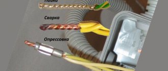
For example, it talks about the most preferred methods of connecting aluminum plates - soldering or welding and aluminum tips - crimping or welding.
Welding and soldering
electric welding
soldering wires
However, this type of docking cannot be classified as simple. It requires special equipment, which even 90% of electricians often do not have available.
And even with its help it is not always possible to connect an aluminum monocore wire with a flexible copper stranded one. In addition, you are forever tied to an outlet or extension cord.
What if there is no voltage or generator nearby?
At the same time, on the contrary, 90% of electrical installers have elementary press pliers. It is not necessary to purchase the most expensive and sophisticated ones for this.
For example, batteries. It’s convenient, of course, just walk and press a button.
The Chinese counterparts also cope well with their task of crimping. Moreover, the entire process takes no more than 1 minute.
What is the best way to reliably connect two cables together?
Methods of connecting cables that require equipment and skills in the field of electrical engineering:
- soldering;
- welding;
- crimping with sleeves.
Simple connection methods that do not require tools or knowledge:
- connection using terminal blocks;
- spring clamps;
- PPE caps;
- bolted connection.
The choice of connection method depends on the characteristics of the wires. It is necessary to take into account the type and material of the core, the number of wires, and operating conditions.
Aluminum
Aluminum wires can also be connected using any method, but with some special features. When connecting, the metal must be manually stripped of insulation.
Copper and aluminum wires cannot be connected directly. The connection point becomes very hot and over time the contact weakens. Therefore, it is better to use terminal blocks, wago, bolt connection or special branch clamps.
Copper
Copper wire can be connected using terminal blocks, Wago clamps (necessarily using special paste), using a bolt, or soldering.
Selecting a connection method
There are a lot of methods for combining cables. The desired option is chosen taking into account the situation. For temporary mating, the bolting method or twisting is used, for permanent mating, soldering or crimping is used.
Stranded and single-core conductors
In this case, work begins with choosing the ratio of conductor sections. The multi-core element should not be thinner than a single element. In this case, the contact may be destroyed. The wires are fastened by welding, soldering or crimping. When using a soldering iron, the ends of the cables are cleared of braid. The multi-core element is wound onto a single element.
The soldering area is carefully insulated. When crimping, a sleeve is put on the ends of the wires, which is clamped with pliers.
Wires with cross-sections of different diameters
The connection in this case requires calculation of the current density. If the parameter is acceptable, the elements are fastened with bolts, clamps, soldering or twisting. The process is no different from that when working with the same conductors.
Large conductors
The connection is difficult to make due to the large contact area. Fixing thick wires is only possible by welding. It cannot be done at home, since the conductors must be heated to a high temperature. After welding is completed, check the functionality of the wiring. When splicing thick cables, you can use a coupling.
Broken wires in the wall
Wiring in the pipe may be damaged during repair work. Troubleshooting begins after the power supply is turned off. The broken wires are connected like this:
- Using special tools, they look for the break point. Remove the layer of plaster, gaining access to the desired area.
- Remove insulation from the ends of the damaged cable. Treat bare areas with molten solder.
- Select a second cable of the appropriate cross-section. It is cut off and soldered to both ends of the damaged wire. The length being extended should not be too short or long.
- Insulate the soldering area. To do this, use a heat-shrink tube, which is put on the repaired area. When heated with a hair dryer, the material tightly envelops the joint.
Connecting electrical wires by twisting
Until recently, twisting was the most common method of connecting wires when doing electrical wiring; due to its accessibility, all it took was a knife and pliers. But, according to statistics, twisting is an unreliable way to connect conductors.
According to the electrical installation rules (PUE), twisted connections when installing electrical wiring are prohibited. But, despite the noted disadvantages, the twisting method is currently widely used. Connecting conductors of low-current circuits by twisting, subject to certain rules, is quite justified.
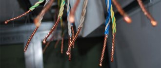
The photo on the left shows how twisting is unacceptable. If one conductor is twisted around another, the mechanical strength of such a connection will be insufficient. When twisting wires, you must make at least three turns of wires around each other. In the middle photo, the twisting is done correctly, but a copper conductor is twisted with an aluminum one, which is not permissible, since when copper comes into contact with aluminum, an emf of more than 0.6 mV occurs.
In the photo on the right, the twisting of copper and aluminum wires is done correctly, since the copper wire is tinned with solder before twisting. You can twist several wires together at once; in a junction box, sometimes up to 6 conductors are twisted, wires of different diameters and from different metals, a stranded wire with a single-core wire. Only the stranded wire needs to be made single-core by first soldering it with solder.
In what cases will it be necessary to connect cables?
The procedure is carried out when repairing existing wiring or installing new wiring, as well as when eliminating previously made errors.
Connecting cables are needed both when supplying electricity to the site and at home. All methods are divided into 2 categories:
- not requiring the use of special equipment;
- which require appropriate skills and professional equipment.
All types of work are carried out in compliance with safety regulations.
What is wire twisting and why is it dangerous?
Several decades ago, when the load on electrical wiring was not so great, such a connection was popular. Moreover, experienced craftsmen taught me, then a young electrician, to first thoroughly strip the metal cores, twist them tightly, and crimp them with pliers.
The length of this twist had to be created on the order of 10 cm to ensure good electrical contact, as shown in the lowest example. And they would reject anything higher, despite its beauty.
Inside closed, dry rooms, such twists worked for years and decades. However, many electricians violated the technology and created poor-quality contact.
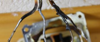
In addition, in a humid environment, the metal oxidizes. The electrical resistance of its transition surface layer deteriorates. This leads to increased heating of the cores and premature damage to the insulation.
Therefore, modern rules, in particular the PUE, prohibit simple twisting of wires, no matter how beautifully and reliably it is done.
Particularly dangerous are twists of aluminum wires, as well as cores made of different metals - copper and aluminum.
This is due to the high ductility of soft aluminum and its high ability to create, under the influence of atmospheric oxygen, an outer layer of oxides that protects the internal structure of the metal. This film reduces conductivity.
When currents flow with increased loads, aluminum, which has a high coefficient of linear expansion, heats up, increasing its volume. After cooling, it contracts, breaking the tightness of the joint.
Each heating and cooling cycle degrades the electrical performance of the strand. In addition, copper and aluminum work as a galvanic couple, and these are additional chemical reactions with the formation of surface oxides.
Recommendation: wherever you find a simple twist, get rid of it. Reinforce it by soldering, welding, crimping or any other approved method.
Connecting wires easily
You can put the duty tape in the back drawer: you won’t need it anymore. Instead of this:
- We go to the nearest store and buy terminals (clamps). The asking price is 8–50 rubles. It is advisable to take WAGO 222 terminals with levers. As the electrician explained, they are the most reliable and easiest to use.
- We strip both wires to the depth of the terminal block, approximately 1 cm.
- We collect the strands of the stranded wire into a tight bundle and twist them slightly.
- Both conductors must be straight and clean.
- Raise the levers and insert both wires into the holes. We clamp by lowering the levers down.
Ready. With this connection method, you do not need to think about the quality of twisting and insulation. The length of the wiring remains the same. If necessary, the lever can be lifted and the wire removed - that is, the clamp is reusable.
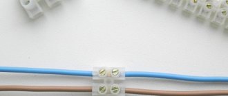
The WAGO 222 clamp comes with 2 holes or more. It is designed for connecting single- and multi-core copper wires with a cross-sectional area of 0.08–4 mm, used in household electrical networks with voltages up to 380 V. Using the terminal block, lamps, electricity meters, garlands and much more are connected.
Types of terminal blocks
It is worth saying that terminal blocks are different:
- Screw terminals in polyethylene sheath. The most common, inexpensive and structurally simple. Inside the insulating shell there is a brass sleeve with two screws - they are used to screw the wires inserted into the holes on both sides. The downside is this: screw terminals are not suitable for aluminum conductors and stranded wires. Under constant pressure from the screw, the aluminum becomes fluid and the thin strands are destroyed.
- Screw terminal blocks with metal plates. More reliable design. The wires are clamped not with screws, but with two plates with characteristic notches. Due to the increased clamping surface, these terminals are suitable for stranded wires and aluminum.
- Self-clamping express terminal blocks. No less simple design, but much more convenient. It is enough to push the wire into the hole until it stops, and it will be securely clamped. Inside there is a miniature tinned copper shank and a fixing plate. Manufacturers also often place a paste inside - a mixture of technical petroleum jelly and quartz sand. It removes the oxide film from the surface of aluminum and subsequently prevents it from forming again.
To connect an aluminum wire to a copper wire (no matter how many wires they have), you need a special terminal block with paste. The fact is that copper and aluminum form a galvanic couple
When metals interact, the destruction process starts. The resistance at the connection point increases, as a result of which the structure begins to heat up. This often leads to melting of the insulation or, even worse, sparking. The higher the current, the faster the destruction occurs.
Connecting electrical wires by soldering
The connection of copper wires with high-quality soldering is the most reliable and is practically not inferior to a solid wire. All of the above examples of twisted wires, except for aluminum and tinsel, when tinning the conductors before twisting and then soldering them with solder, will be reliable on a par with solid wires. The only drawback is the extra labor involved, but it's worth it.
If you need to connect a pair of wires and the twisted conductors must be directed in different directions, then a slightly different type of twist is used.
By splicing two pairs of double wires in the manner described below, it is possible to obtain a compact and beautiful connection by twisting both single-core and stranded pairs of conductors. This twisting method can be successfully used, for example, when splicing broken wires in a wall, extending a wire when moving a socket or switch from one place on the wall to another, when repairing or extending the length of a carrying cable.
To obtain a reliable and beautiful connection, it is necessary to adjust the lengths of the ends of the conductors with a shift of 2-3 cm.
Remove the insulation from the ends of the wires.
Twist the conductors in pairs. With this type of twisting, two turns are enough for a single-core wire, and five for a multi-core wire.
If you plan to hide the twists under plaster or in another inaccessible place, then the twists must be soldered. After soldering, you need to go over the solder with sandpaper to remove any sharp solder icicles that could pierce the insulation and stick out from it. You can do without soldering if the connection is accessible and there is a small current flowing through the conductors, but the durability of the connection without soldering will be much lower.
Due to the shift of the twisting points, there is no need to insulate each of the connections separately. We attach a strip of insulating tape on both sides along the conductors. Finally, you need to wind three more layers of insulating tape. According to the requirements of the Electrical Safety Rules, there must be at least three layers.
Wires spliced and soldered in the manner described above can be safely laid in the wall and plastered on top. Before installation, it is advisable to protect the connection with a vinyl chloride tube placed in advance on one of the pairs of wires. I have done this many times, and the reliability has been confirmed by time.
Solder paste for soldering without a soldering iron
Solder paste includes flux and solder. This is very convenient when soldering without a soldering iron. There is no need to tinker with these two components separately. It is enough to apply the paste once to the junction of the wires and then heat it to the melting temperature of the solder.
Solder paste consists of metal powder, flux, and fixative (an adhesive substance to hold the alloy in a liquid state within the soldering area). The paste contains tin and lead powder with the addition of silver. The proportions of the composition vary depending on the purpose of the product.
Soldering with a lighter
When heated, the flux instantly evaporates, the solder firmly and tightly covers the entire twist of wires. The result is high quality soldering. The applied composition allows you to do without soldering irons and soldering stations.
For food soldering, it is recommended to use the following brands of pastes: POS 63, POM 3 and others. Paste soldering is used to work with microcircuits, where instead of soldering irons, thin metal rods are used, heated by external heat sources.
Solder paste
Terminals
Terminal blocks for connecting wires provide one undeniable advantage: they can connect cores of different metals. Both here and in other articles, we have repeatedly reminded that twisting aluminum and copper wires together is prohibited. The resulting galvanic couple will result in corrosion processes and destruction of the connection. And it doesn’t matter how much current flows at the connection. Late or early, the twist will still start to heat up. Terminals are the way out of this situation.
Terminal block
The simplest and cheapest solution is polyethylene terminal blocks. They are not very expensive and are sold in every electrical goods store.
The polyethylene frame is designed for several cells, inside each there is a brass tube (sleeve). The ends of the connected wires must be inserted into this sleeve and clamped with two screws. It is very convenient that as many cells are cut from the block as it is necessary to connect pairs of wires, for example, in one junction box.
But not everything is so smooth, there are also disadvantages. At room conditions, aluminum begins to flow under screw pressure. You will have to periodically inspect the terminal blocks and tighten the contacts where the aluminum conductors are fixed. If this is not done in a timely manner, the aluminum core in the terminal block will become loose, lose reliable contact, and, as a result, spark and heat up, which can result in a fire. Such problems do not arise with copper conductors, but it would not be superfluous to periodically inspect their contacts.
Terminal blocks are not intended for connecting stranded wires. If stranded wires are clamped into such connecting terminals, then when tightening the screw under pressure, the thin wires may partially break, which will lead to overheating.
In cases where it becomes necessary to clamp stranded wires into a terminal block, it is imperative to use auxiliary pin lugs. It is very important to choose the correct diameter so that the wire does not jump out later. The stranded wire must be inserted into the lug, crimped using pliers and secured in the terminal block.
As a result of all of the above, the terminal block is an ideal option for single-core copper wires. With aluminum and stranded ones you will have to comply with a number of additional measures and requirements.
How to use terminal blocks is shown in this video:
Terminals on plastic blocks
Another very convenient wire connector is a terminal on plastic blocks. This option differs from terminal blocks in that it has a smooth metal clamp. The clamping surface has a recess for the wire, so there is no pressure on the wire from the screw being tightened. Therefore, such terminals are suitable for connecting any wires.
Everything about these clamps is extremely simple. The ends of the wires are stripped and placed between the contact and pressure plates.
Such terminals are additionally equipped with a transparent plastic cover, which can be removed if necessary.
Self-clamping terminals
Wiring installation using such terminals is simple and quick.
The wire must be inserted into the hole to the very end. There it is automatically fixed using a pressure plate, which presses the wire to the tinned busbar. Thanks to the material from which the pressure plate is made, the clamping force does not weaken and is maintained all the time.
The internal tinned busbar is made in the form of a copper plate. Both copper and aluminum wires can be fixed in self-clamping terminals. These terminals are disposable.
And if you want clamps for connecting reusable wires, then use terminal blocks with levers. They lifted the lever and inserted the wire into the hole, then fixed it there by pressing it back. If necessary, the lever rises again and the wire protrudes.
Try to choose clamps from a manufacturer that has proven itself well. The clamps have especially positive characteristics and reviews.
The advantages and disadvantages are described in this video:
PPE caps – connecting insulating clips
Now let’s look at the PPE spring caps in detail. These clamps have not gained such great popularity among electricians and ordinary people, and there are reasons for this.
Terminal clamp
This device will not be a block, but depending on the model, it can connect up to 8 conductors in one housing.
The outer material is plastic, which has a number of features:
- Does not support combustion even when exposed to open fire;
- Has a high melting point;
- Withstands voltages from 300 to 600 V, which indicates high insulating properties;
- It has high mechanical strength and reliably protects the connection from any damage.
The cap has a cone shape. The outside is corrugated or has two blades for ease of use.
A compression spring of the same shape is installed inside. As was written above, its edges are sharpened in a special way, which allows you to securely fix cores of different sizes.
If we compare PPE with Vago terminals, they will have a couple of obvious disadvantages:
- Inability to simultaneously connect aluminum and copper wires.
- Complicated installation that requires special processing of the wires - it is necessary to thoroughly clean the insulation without protruding even a millimeter of the bare part of the wire beyond the cap body.
- An accurate selection of the cap model for the wire cross-section is required, since the best contact will be in the narrowest place, and if the wires are too thin, there will be increased resistance at the connection point, as when twisting the wires.
- Sufficient force is required to ensure good contact between the conductors.
- The cores must be strictly the same diameter.
- For multi-core wires, this solution will not be the best, since partial damage to thin wires is possible.
PPE caps in the junction box
The cap is installed in the following sequence:
- The wires are exposed from insulation to a length corresponding to the length of the corrugation on the cap;
- Their ends are connected in parallel, without preliminary twisting.
- The cap is placed on top and rotated with force clockwise.
- When connecting three wires, a preliminary twist is made, after which its tip is bitten off.
How PPE works
The following video will show how to install PPE caps.
There are five types of PPE terminals in total, the difference between which can be seen in the following image.
The difference between PPE caps
Interesting to know! PPE 5 can be used to connect 8 cores with a cross section of 2.5 mm2.
The table also shows the color coding of the models. The majority of manufacturers adhere to it, but there is no single standard, so there may be differences, so be careful when purchasing.
Pay attention to the product labeling (PPE 1 1.0-3.0 and similar). It will help you accurately select the product for the cross-section of your wire.
The first digit of the marking indicates the type of housing, the rest indicate the permissible range of cross-sections.
How to connect wires of different sections?
It often happens that wires of different sections come into the junction box and they need to be connected. It seems like everything should be simple here, as with connecting wires of the same section, but there are some peculiarities here. There are several ways to connect cables of different thicknesses.
Remember that you cannot connect two wires of different sections to one contact in a socket, since the thin one will not be pressed tightly by the bolt. This will lead to poor contact, high contact resistance, overheating and melting of the cable insulation.
How to connect wires of different sections?
1. By twisting with soldering or welding
This is the most common way. You can twist wires of adjacent sections, for example 4 mm2 and 2.5 mm2. Now, if the diameters of the wires are very different, then good twisting will no longer work.
When twisting, you need to make sure that both wires wrap around each other. Do not allow a thin wire to wrap around a thick one. This may result in poor electrical contact. Do not forget about further soldering or welding.
Only after this will your connection work for many years without complaints.
2. Using screw clamps ZVI
I already wrote about them in detail in the article: Methods of connecting wires. Such terminal blocks allow you to insert a wire of one cross-section on one side, and a different cross-section on the other side. Here each core is clamped with a separate screw. Below is a table that will help you choose the right screw clamp for your wires.
| Screw clamp type | Cross-section of connected conductors, mm2 | Permissible continuous current, A |
| ZVI-3 | 1 – 2,5 | 3 |
| ZVI-5 | 1,5 – 4 | 5 |
| ZVI-10 | 2,5 – 6 | 10 |
| ZVI-15 | 4 – 10 | 15 |
| ZVI-20 | 4 – 10 | 20 |
| ZVI-30 | 6 – 16 | 30 |
| ZVI-60 | 6 – 16 | 60 |
| ZVI-80 | 10 – 25 | 80 |
| ZVI-100 | 10 – 25 | 100 |
| ZVI-150 | 16 – 35 | 150 |
As you can see, using ZVI you can connect wires of adjacent sections. Also remember to look at their amperage rating. The last digit in the screw terminal type indicates the amount of permissible continuous current that can flow through this terminal.
We strip the wires to the middle of the terminal...
We insert them and tighten the screws...
3. Using Wago universal self-clamping terminals.
Wago terminal blocks have the ability to connect wires of different sections. They have special sockets where each wire “sticks” into. For example, you can connect a 1.5 mm2 wire into one hole of the clamp, and 4 mm2 into the other, and everything will work properly.
According to the manufacturer's markings, terminals of different series can be used to connect wires of different sections. See table below:
| Wago terminal series | Cross-section of connected conductors, mm2 | Permissible continuous current, A |
| 243 | 0.6 to 0.8 | 6 |
| 222 | 0,8 – 4,0 | 32 |
| 773-3 | 0.75 to 2.5 mm2 | 24 |
| 273 | 1.5 to 4.0 | 24 |
| 773-173 | 2.5 to 6.0 mm2 | 32 |
Below is an example with series 222...
4. Using a bolted connection.
A bolted connection of wires is a composite connection consisting of 2 or more wires, a bolt, a nut and several washers. It is considered reliable and durable.
Here it goes like this:
- we strip the core by 2-3 centimeters, so that it is enough for one full revolution around the bolt;
- we make a ring from the core according to the diameter of the bolt;
- take the bolt and put it on the washer;
- We put a ring of conductor of the same section on the bolt;
- then put on the intermediate washer;
- put on a ring made of a conductor of a different cross-section;
- We put the last washer and tighten the whole thing with a nut.
In this way, you can simultaneously connect several wires of different sections. Their number is limited by the length of the bolt.
5. By squeezing the branch “nut”.
I wrote about this connection in detail with photographs and corresponding comments in the article: Connecting wires using nut-type clamps. Let me not repeat myself here.
6. Using tinned copper tips through a bolt with a nut.
This method is well suited for connecting large cross-section cables. For this connection, it is necessary to have not only TML tips, but also crimping pliers or a hydraulic press. This connection will be a little bulky (long), and may not fit into some small junction box, but it still has the right to life.
Unfortunately, I didn’t have a thick wire and the necessary tips on hand, so I made a photo from what I had. I think you can still understand the essence of the connection from it.
Let's smile:
Scotch-lock
Couplings of this type are for one-time use. Used for wires with low operating currents (telephone lines or wires for low-power LED lamps).
These clamping couplings make connections by means of a mortise contact. The wires don't even need to be stripped before connecting. They are inserted directly into the insulating layer into adhesive tape and crimped with pliers. The plate, which has cutting contacts, cuts into the insulating layer, due to which contact between the cores occurs.
In addition to the fact that stripping of cores is not required, adhesive locks have a number of other advantages:
- low cost;
- versatility;
- no special devices are needed, crimping is done with ordinary pliers;
- waterproof (there is a hydrophobic gel inside the coupling, which protects the contact connection from moisture and corrosion).
- If the Scotch-lock coupling needs to be replaced, it is simply cut out and a new one is installed in its place.
Rules for connecting a stranded conductor
Very often, when laying a multi-core cable or wire, it becomes necessary to connect it to such common elements of the electrical circuit as a circuit breaker, socket, meter, plug, lamp socket, and so on. Most often, copper wires are used, especially in everyday life. The main task is to ensure reliable contact with the clamping bolted connection of these devices and devices, and therefore to make the stranded wire as monolithic and homogeneous as possible. You can perform this procedure in several ways:
- Twist all the thin strands into a tight bundle and, if the cross-section allows, bend it in the opposite direction. This can be done with pliers or by hand, it all depends on the cross-section of the conductor. This method is the simplest and is used in modern wiring only in emergency cases, but it also has a right to exist. It will not be possible to perform this procedure with a large cross-section cable in this way, so it is more suitable for supplying voltage to a plug, socket, or socket of a low-power lighting fixture.
- By tinning the conductor. This method is more effective than the previous one and will ensure reliable contact. Its main disadvantage is that you do not always have a soldering iron at hand, and even electricity for its operation. Tinning can be done either with a straight conductor or with a terminal block bent into a ring along the diameter of the bolt, but before doing this, again, it is necessary to tightly twist all the thin wires. This method can be applied in all cases of connection to electrical appliances, to a machine, socket, etc., if the cross-section allows it.
- Tip crimping. The tips allow you to achieve reliable and durable contact without soldering. There are two types of tips: bolt-on and simply sleeved. Depending on the element to be connected, you need to select the appropriate type and appropriate cross-section. With a tip and sleeves you can connect any type of cable, of any cross-section, both stranded and single-core, but for this you will need a special tool that will need to be purchased before carrying out installation work, especially at a professional level. Connecting a stranded wire in this way in the panel, to the terminal block, to the meter not only looks aesthetically pleasing and correct, but also reduces the likelihood of heating at the connection points. The photo below shows NShVI type lugs on stranded wires.
Although tinning is a good method, in practice the cores are often terminated with lugs; this is faster, easier and often more reliable than other methods. However, do not crimp the tips with pliers - the core will simply jump out of them and you will not get a good connection. To do this, it is better to buy crimping pliers with square dies; you can find them for about 1000 rubles.
Sleeves
When powerful clamps for several wires are needed, sleeves are used. They are a tinned copper tube or a flat tip with a hole made for fastening.
All connected wires must be inserted into the sleeve and crimped using a special crimper device (crimping pliers). This wire clamp has a number of positive aspects:
- It is very convenient to use lugs with holes when there is a need to secure wire assemblies to housings with screws.
- Crimping at the connection does not increase the resistance.
As you can see, there are a lot of wire clamps, each with its own advantages and disadvantages. Choose based on which wires you need to connect and where the connection will be located. But do not forget that the most important thing in electricity is reliability and safety.
What is required for soldering
This process does not require special equipment, so soldering can be done by anyone. So, during the work you will need the following tools and materials:
- Electric soldering iron with a power of at least 80 W;
- Cleaning agents (flux, rosin, mixture diluted on their basis);
- Solders suitable for the wire material;
- Wooden or plastic stand;
- File, sandpaper for sharpening;
- Pliers or tweezers for holding wires;
- Alcohol for treating the surface of the cord;
- Insulating tape;
- Heat shrink tubes.
The choice between rosin and flux is determined by the availability of the product and certain points. Thus, it is more convenient to use flux, since the wires are processed quickly, but there is a risk of poor-quality washing and gradual corrosion of the sheath.
Solders are selected taking into account the conductor material. For soldering aluminum wires, zinc products (TsO-12, TsA-15, P250A) are better suited, and for working with copper, POS 40, 50, 60 made of tin and lead are recommended. Solders with the addition of rosin are convenient, which eliminates the need to clean the phases.
Spring clamps for connecting wires
One of the most controversial ways to connect wires is using spring clamps. There are several types, but the two most common are wago terminal blocks and PPE caps. Externally and in terms of installation method, they are very different, but both designs are based on a spring, which creates strong contact with the wire.
There is controversy about this spring. Opponents of using wago say that the spring will weaken over time, the contact will become worse, the connection will begin to heat up more and more, which, again, leads to an even more rapid decrease in the degree of elasticity of the spring. After some time, the temperature may rise so much that the body (plastic) will melt, but what can happen next is known.
Spring clamps for electrical wiring - popular connections for wires
In defense of using spring clamps to connect wires, if they are used according to manufacturers' recommendations, problems are very, very rare. Although there are many fakes of both wago and PPE, as well as a sufficient number of photographs of them in melted form. But, at the same time, many people use them, and, under normal operating conditions, they work for years without complaints.
Soldering process with an electric soldering iron
The entire technology of soldering wires with a soldering iron can be divided into several successive stages. All of them are repeated in a certain sequence:
- Training of conductors. When soldering wires, they are freed from insulation. After this, the oxide film is removed from them mechanically. You can use a small piece of fine-grit sandpaper. The metal should shine and be light.
- Tinning. Heat the soldering iron to the melting temperature of the rosin (it begins to actively melt when touched). Take a conductor, bring it to a piece of rosin, heat it with a soldering iron so that the entire stripped part of the wire is immersed in rosin. Then take a drop of solder onto the soldering iron tip and spread it over the treated part of the conductor. The solder spreads quickly, covering the wire with a thin layer. To make it distributed faster and more evenly, the wire is turned slightly. After tinning, copper conductors lose their redness and become silvery. This is how all wires that need to be soldered are processed.
- The tinned conductors are folded together, straightening them with your fingers so that they fit snugly against each other. If the soldering needs to be long, you can twist it. Holding the conductors, take solder onto the tip, press it to the soldering site, applying some force. At the same time, the soldering area heats up, the rosin begins to boil, and the solder spreads. When it covers the entire area and flows between the conductors, we can consider that soldering the conductors with a soldering iron is completed. They are held motionless for some time - until the solder cools down (to speed up the process, they blow on this place).
That's all. In the same way, you can solder two or more wires, you can solder a wire to some contact pad (for example, when soldering headphones, you can solder the wire to a plug or to a pad on a headphone), etc.
After you have finished soldering the wires with a soldering iron and they have cooled down, the connection must be insulated. You can wrap electrical tape, put it on, and then heat up the heat shrink tube. When it comes to electrical wiring, it is usually recommended to first screw on a few turns of electrical tape, and then put a heat-shrinkable tube on top, which is heated.
Differences in technology when using flux
If active flux is used rather than rosin, the tinning process changes. The cleaned conductor is lubricated with the compound, and then heated with a soldering iron with a small amount of solder. Further everything is as described.
Soldering twists with flux - faster and easier
There are also differences when soldering twists with flux. In this case, you can not tin each wire, but twist it, then treat it with flux and immediately start soldering. The conductors don’t even need to be cleaned—the active compounds corrode the oxide film. But instead, you will have to wipe the soldering areas with alcohol to wash away the remnants of chemically aggressive substances.
Features of soldering stranded wires
The soldering technology described above is suitable for monocores. If the wire is multi-core, there are nuances: before tinning, the wires are untwisted so that everything can be dipped in rosin. When applying solder, you need to make sure that each wire is covered with a thin layer of solder. After cooling, the wires are twisted into one bundle again, then you can solder with a soldering iron as described above - dipping the tip into solder, heating the soldering area and applying tin.
When tinning, multi-core wires must be “fluffed”
Is it possible to solder copper wire to aluminum
Aluminum cannot be combined directly with other chemically active metals. Since copper is a chemically active material, copper and aluminum are not joined or soldered. The point is too different thermal conductivity and different current conductivity. When current passes, aluminum heats up more and expands more. Copper heats up and expands much less. Constant expansion/constriction to varying degrees leads to the fact that even the best contact is broken, a non-conducting film is formed, and everything stops working. That's why copper and aluminum are not soldered.
If there is such a need to connect copper and aluminum conductors, make a bolted connection. Take a bolt with a suitable nut and three washers. At the ends of the connected wires, rings are formed according to the size of the bolt. Take a bolt, put on one washer, then a conductor, another washer - the next conductor, a third washer on top and secure everything with a nut.
Aluminum and copper conductors cannot be soldered
There are several other ways to connect aluminum and copper lines, but soldering is not one of them. You can read about other methods here, but bolted is the simplest and most reliable.
Wire Mounting Clamps
Let's move on to the second type of clamps, which are necessary when installing electrical networks. If the previously discussed options are used for switching conductors, then everything that will be presented in this chapter is used for fixing wires.
Linear tension wire clamp
All clamps that are used to secure cables and wires are divided into supporting ones (they are suspended on intermediate supports) and tension ones, which are held on anchor-type supports.
Clamps are also divided according to strength:
Clamps for linear wires are blind
- Blind - the strength of the sealing of these devices varies from 30 to 90% of the strength of aluminum wires or 10-15% of steel cables. If there is a break on one of the spans, the wire does not jump out of the clamp, but the tension from it is transferred to the support. This type is the most common when installing overhead power lines.
- Drop-out or releasing - they throw out a boat with a wire when the support garland is deflected at an angle of about 40 degrees, which ensures that there is no additional pressure on the support and a reduction in its mass. Today they are not used due to frequent cases of spontaneous ejection.
- Multi-roller - in fact, this is not quite a clamp, since the wire inside them rolls over the rollers, depending on the tension force in the adjacent spans.
- Pressed tension type clamps – This is a steel anchor in which the wire is pressed.
Wire clamp on pole
- Wedge clamp - consists of three metal parts: a base, a wedge and a pressure plate. When the wire is tensioned, it is held in place due to the high friction force. The parts wedge into each other.
In particular, the last version of the clamp can be installed with your own hands. The option shown in the photo above is used for fastening low-voltage wires and optical communication cables.
Scotchlok connector
Sometimes it is necessary to use an unbroken cable for connection. Of course, you can always cut it and make, for example, a three-way connection. There is a practice for this, which consists of removing a small section of the insulation of the wire and wrapping it with another. However, a much better solution is available - Scotchlock couplings, shown in the picture.
This connector has two tracks. One of them slides along the main wire (insulated), and the other for the butt wire. The entire connector on both wires is covered, which may require the use of pliers, especially with larger gauge wires or thicker insulation. When closing the connector, a special knife is pressed into the insulation, which, after passing through it, touches the inner conductor, closing both wires located in the element. This type of technology (with cut contact insulation) is called IDT.
Tips from experienced installers
There are many controversial issues both in connection methods and in the use of individual mounting products. But a number of rules apply to absolutely all craftsmen who do electrical installations.
For example, it is strictly prohibited to twist aluminum conductors with copper ones . The process of rapid oxidation leads to the destruction of the commutation and the creation of a dangerous point, which can spark or flare up at any time.
When using electrical tape, overlap the wraps. One layer is not enough, it is better to go along the connection 2-3 times, making sure to make the last turn on the insulation
Single conductors in screw terminals are held loosely. Therefore, it is recommended to bend the stripped end in half or make an arbitrary loop out of it.
At the end of the work, be sure to check the reliability of the connections - lightly tug the wires. It happens that the switching is unsuccessful, and the core simply slips out of the terminal block.
If the volume of the distribution box allows, for example, the panels accommodate a lot of wires and devices, then leave the cable with a reserve. Sometimes switching is required and the extra length is useful if the connections are permanent or burnt.
But welding is still preferable
In terms of connection strength and contact quality, welding surpasses all other technologies. Recently, portable welding inverters have appeared that can be transported to the most inaccessible places. Such devices are easily held on the welder's shoulder using a belt. This allows you to work in hard-to-reach places, for example, welding from a stepladder in a distribution box. To weld metal cores, carbon pencils or copper-plated electrodes are inserted into the holder of the welding machine.
The main disadvantage of welding technology - overheating of the parts being welded and melting of the insulation - is eliminated using:
- Correct adjustment of the welding current 70–120 A without overheating (depending on the number of welded wires with a cross-section from 1.5 to 2.0 mm).
- The duration of the welding process is no more than 1–2 seconds.
- Tightly pre-twist the wires and install a copper heat sink clamp.
When connecting wires by welding, the twisted wires should be bent and the cut side must be turned upward. An electrode is brought to the end of the wires connected to ground and the electric arc is ignited. The molten copper flows down in a ball and covers the twisted wire with a sheath. During the cooling process, an insulating belt made from a piece of cambric or other insulating material is put on the warm structure. Lacquered fabric is also suitable as an insulating material.
Sources
- https://YaElectrik.ru/elektroprovodka/skrutka-provodov
- https://StrojDvor.ru/elektrosnabzhenie/kak-pravilno-skruchivat-provoda-mezhdu-soboj/
- https://electrik-ufa.ru/provoda-i-kabelya/kak-pravilno-delat-skrutku-mednyh-provodov
- https://domashnysvet.ru/elektroprovodka/delaem-pravilnuyu-skrutku-provodov
- https://ElektrikExpert.ru/kak-pravilno-skruchivat-provoda.html
- https://elektro-enot.ru/kak-pravilno-sdelat-skrutku-provodov/
- https://electrikexpert.ru/kak-pravilno-sdelat-skrutku-provodov/
- https://ProFazu.ru/provodka/montazh/skrutka-provodov.html
- https://ichip.ru/sovety/remont/soedinyaem-provoda-kak-professionaly-kak-pravilno-delat-skrutku-711872
- https://zen.yandex.ru/media/asutpp.ru/kak-pravilno-sdelat-skrutku-mednyh-provodov-poleznye-sovety-5d6a002003bdd400ac889b29
- https://electry.ru/elektromontazhnye-raboty/sposobyi-soedineniya-provodov.html
Modern technologies
In many cases, the methods discussed are gradually becoming a thing of the past. They were replaced by factory wire connectors, which made installation and switching work much easier and faster:
- Terminal blocks, inside of which there are tubular brass sleeves. Stripped wire strands are inserted into these tubes and secured by tightening the screws.
- PPE caps, inside of which there are compression springs. The cores are inserted into the cap and then turned clockwise with little effort, thereby reliably compressing the connected wires inside.
- Self-clamping terminals. It is enough to place the wiring in them, and there it is automatically fixed due to the pressure plate.
- Lever-type terminal blocks. This connecting element is reusable. It is enough just to lift the lever, insert the conductor into the contact hole and lower the lever back, reliable fixation is ensured.