| INTERSTATE COUNCIL FOR STANDARDIZATION, METROLOGY AND CERTIFICATION (MGS) INTERSTATE COUNCIL FOR STANDARDIZATION, METROLOGY AND CERTIFICATION (ISC) | |
| INTERSTATE | GOST 30324.2.9- |
| STANDARD | 2012 |
| (IEC 60601-2-9: 1996) | |
MEDICAL ELECTRICAL PRODUCTS
Part 2-9
Particular safety requirements for radiation therapy dosimeters electrically connected to radiation detectors in contact with the patient
(IEC 60601-2-9:1996, MOD)
Official publication
Moscow
Standardinform
2014
Content
Section one. General provisions………………………………….1
1 Scope and purpose…………………………………….1
2 Definitions………………………………………………………………. 2
5 Classification………………………………………………………2
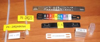
6 Identification, marking and documentation……………………………..2
Section two. Environmental conditions…………………………….3
Section three. Protection against electrical hazards………………..3
15 Voltage and (or) energy limitation…………………………….3
Section four. Protection against mechanical hazards…………………………3
21 Mechanical strength……………………………………..3
Section five. Protection from the hazards of unwanted or excessive radiation………….4
Section six. Protection against the danger of ignition of flammable anesthetic mixtures…………4
Section seven. Protection from excessive temperatures and other hazards………………4
44 Overflow, splashing, leakage, moisture, liquid penetration, cleaning, sterilization
and disinfection………………………………………………………4
Section eight. Precise performance and protection from hazardous outputs
characteristics ……………………………………………………… 4
50 Performance Accuracy……………………………………4
Section nine. Abnormal operation and disturbance conditions; external influence tests
factors……………………………………………………5
Section ten. Design requirements……………………………..5
Appendix L (informative) Publications referred to in this standard……………6
Appendix AA (reference) Alphabetical index of terms…………………7
"Z
GOST 22483—2021
(IEC 60228:2004)
INTERSTATE STANDARD
CURRENT CONDUCTING CONDUCTORS FOR CABLES, WIRES AND CORDS
Conductors for cables, wires and cords
Introduction date: 2021—09—01
1 area of use
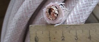
This standard applies to single-wire and multi-wire conductors made of copper, aluminum and aluminum alloy intended for cable products for stationary installation, self-supporting insulated and protected wires for overhead power lines, as well as flexible conductors.
This standard establishes nominal cross-sections up to 2500 mm2 inclusive of current-carrying cores (hereinafter referred to as cores) of electrical cables, wires and cords of a wide range of types. This standard also contains requirements regarding the number and diameter of wires and electrical resistance values.
This standard does not apply to the conductors of communication cables, radio frequency cables, bare wires and winding wires.
The application of this standard for special types of cables and wires (for an operating temperature of 120 °C and above, especially flexible, low-inductance, pulsed, ignition, load-carrying, geophysical, ship sealed, alarms and interlocks, etc. for narrow-purpose purposes) is established in standards or technical specifications for these types of cables and wires.
Unless otherwise specified in a special clause of the contract, this standard applies to the cores of finished cable products, and not to individual cores or cores supplied through cooperation for the manufacture of cable products.
- 8 of this standard includes reference annexes that provide additional information regarding the correction temperature coefficients used in measuring electrical resistance (see Appendix B) and the limiting sizes of round conductors (see Appendix C).
2 Terms and definitions
8 of this standard the following terms with corresponding definitions are used:
- 2.1 metal-coated: A surface layer of a suitable metal, such as tin or a tin-based alloy.
- 2.2 nominal cross-sectional area value identifying a specific conductor size but not verifiable by direct measurement.
- 2.3 wire: A metal element of a cable product with a constant cross-section, made by drawing.
Note - For each specific core size there is a requirement for a maximum electrical resistance value. The actual cross-section of the conductors may differ from the nominal one if the electrical resistance meets the requirements of this standard.
Official publication
3 Classification
The veins are divided into six classes (1-6):
- • class 1 - single-wire and multi-wire (for large cross-sections) conductors;
- • class 2 - stranded conductors;
- • class 3 - stranded flexible conductors with flexibility greater than the flexibility of class 2 conductors;
- • class 4 - stranded flexible conductors with flexibility greater than the flexibility of class 3 conductors;
- - class 5 - flexible conductors;
- • class B - flexible conductors with flexibility greater than the flexibility of class 5 conductors.
Cores of classes 1 and 2 are intended for cable products for stationary installation. Cores of classes 3, 4, 5 and 6 are intended for flexible cable products, but they can also be used for cable products for stationary installation.
4 Materials
- 4.1 Introduction
The cores must consist of one of the following materials:
- • annealed copper with or without metal coating;
- - aluminum or aluminum alloy.
- 4.2 Solid aluminum conductors
Single-wire round and shaped aluminum conductors must be made of aluminum that provides the tensile strength of the finished conductor within the limits specified in Table 1.
Table 1 - Tensile strength of the finished core
| Nominal cross-section, mm2 | Tensile strength. N/ny2 |
| 10 and 16 | 110—165 |
| 25 and 35 | 60—130 |
| 50 | 60—110 |
| 70 or more | 60—90 |
| Note - The given values do not apply to aluminum alloy conductors. |
- 4.3 Stranded aluminum conductors
Stranded round and shaped aluminum conductors must be made of aluminum. which provides tensile strength of individual wires within the limits specified in table 2.
Table 2 - Tensile strength of individual wires
| Nominal cross-section, mm2 | Tensile strength. N/mm2 |
| 10 | Up to 200 keys |
| 16 or more | 125—205 |
Notes
|
5 Single-wire and multi-wire conductors
The cores should not have burrs, cutting edges or bulging of individual wires.
- 5.1 Single-core and multi-wire (for large cross-sections) conductors (class 1)
5.1.1 Design
- a) For single-wire and multi-wire (for large cross-sections) conductors (class 1), use one of the materials given in section 4.
- b) Single core copper conductors shall be round. For multi-core cables and wires, it is allowed to use shaped single-wire copper cores with a cross-section of 25-50 mm2.
Note - Solid copper conductors with a nominal cross-section of at least 70 mm2 are intended for special types of cables, for example with mineral insulation, but not for cables of general use.
- c) Single core conductors of aluminum and aluminum alloy with a nominal cross-section up to and including 35 mm2 must be round. Larger gauge conductors must be round for single-core cables and wires and may be round or shaped for multi-core cables and wires.
For multi-core cables and wires, it is allowed to use shaped single-core conductors made of aluminum and aluminum alloy with a cross-section of 25 and 35 mm2.
- 5.1.2 Electrical resistance
Electrical resistance of the core at a temperature of 20 * C. determined in accordance with Section 7 shall not exceed the value specified in Table 3.
Table 3 - Single-core and multi-wire (for large cross-sections) class 1 conductors for single-fired and multi-core cables and wires
| Nominal cross-section, mm2 | Minimum number of l roe o lo K Zh1/L y | Electrical resistance of 1 x mm of conductor at a temperature of 20 * C. Ohm. no more | |||
| Si | At | Round Annealed Copper Cores | Round or shaped conductors made of aluminum or aluminum alloy* | ||
| without coatings | with metal coating | ||||
| 0.03 | 1 | — | 588.0 | 617,3 | — |
| 0.05 | 1 | — | 347.9 | 365.3 | — |
| 0.08 | 1 | — | 225.3 | 238.8 | — |
| 0.12 | 1 | — | 130.8 | 138.6 | — |
| 0.20 | 1 | — | 88.8 | 90,4 | — |
| 0.35 | 1 | — | 50.7 | 51,8 | — |
| 0.50 | 1 | — | 36.0 | 36.7 | — |
| 0.75 | 1 | — | 24,5 | 24.8 | — |
| 1.0 | 1 | — | 18.1 | 18.2 | — |
| 1.5 | 1 | 1 | 12.1 | 12.2 | 18.1a |
| 2.5 | 1 | 1 | 7.41 | 7.56 | 12.1* |
| 4 | 1 | 1 | 4.61 | 4.70 | 7,41“ |
| 6 | 1 | 1 | 3.08 | 3.11 | 5.11 |
| 10 | 1 | 1 | 1,83 | 1.84 | 3.08 |
| 16 | 1 | 1 | 1.15 | 1.16 | 1.91 |
| 25 | 1 | 1 | 0.727 | — | 1.20 |
End of table 3
| Nominal cross-section, us2 | LL compress spruce but about the number of core wires | The electrical resistance of 1 km of conductor is at a temperature of 20 * C. Ohm. no more | |||
| Si | A.I. | Round Annealed Copper Cores | Round or shaped conductors of aluminum or aluminum alloy^ | ||
| without cover | with metal coating | ||||
| 35 | 1 | 1 | 0.524 | — | 0.868a |
| 50 | 1 | 1 | 0.387 | — | 0.641 |
| 70 | 1 | 1 | 0.268b | — | 0.443 |
| 95 | 1 | 1 | 0.193° | — | 0.320th |
| 120 | 1 | 1 | 0.153° | — | 0.253rd |
| 150 | 1 | 1 | 0,124° | — | 0.206th |
| 185 | 1 or 35 | 1 | 0.101ь | — | 0.164th |
| 240 | 1 or 35 | 1 | 0.0775° | — | 0.125th |
| 300 | 1 or 35 | 1 | 0,0620° | — | 0.100th |
| 400 | 1 or 35 | 1 or 35 | 0.0465th | — | 0.0778 |
| 500 | 35 | 1 or 35 | 0,0366 | — | 0.0605 |
| 625, 630 | 59 | 1 or 59 | 0,0283 | — | 0.0469 |
| 800 | 59 | 1 or 59 | 0,0221 | — | 0.0367 |
| 1000 | 59 | 1 or 59 | 0,0176 | — | 0.0291 |
| 1200 | — | 1 | — | — | 0.0247 |
a Aluminum conductors with a nominal cross-section up to 35 mm2 inclusive are round only; see 5.1.1. listing c).
b See note to 5.1.1. item b).
e See note to 5.1.2.
d For single-core cables, four sectored core pieces can be combined to form a round core. The maximum electrical resistance of the formed core must be equal to 25% of the value for each of the four sector parts of the core.
NOTE For single-wire aluminum alloy conductors having the same nominal cross-section. As for aluminum conductors, the value of electrical resistance indicated in Table 3 must be multiplied by a factor of 1.162, unless otherwise specified in the agreement between the manufacturer and the customer.
- 5.2 Stranded round unsealed conductors (class 2)
5.2.1 Design
- a) For stranded round unsealed conductors (class 2), use one of the materials listed in section 4.
- b) The nominal cross-section of stranded aluminum or aluminum alloy power cables must be at least 10 mm2.
- c) All wires of each core must be of the same nominal diameter.
- d) The number of wires of each core must be at least the number of wires indicated in Table 4.
Table 4 - Class 2 multi-fiber conductors for single-core and multi-core cables and wires
| Nominal cross-section, mmg | Minimum number of core wires | Electrical resistance of 1 conductor at a temperature of 20 'C. Ohm. no more | |||||||
| steep | steep compacted | shaped | Vein and annealed copper | Aluminum or aluminum alloy core* | |||||
| Si | A.I. | Si | Ai | Si | A.I. | Uncoated wire | Profile with metal coating | ||
| 0.5 | 7 | — | — | — | — | — | 36.0 | 36.7 | — |
| 0.75 | 7 | — | — | — | — | — | 24.5 | 24.8 | — |
| 1.0 | 7 | — | — | — | — | — | 18.1 | 18,2 | — |
| 1.5 | 7 | 7 | 6 | — | — | — | 12.1 | 12.2 | 227 |
| 2.5 | 7 | 7 | 6 | — | — | — | 7.41 | 7,56 | 724 |
| 4 | 7 | 7 | 6 | — | — | — | 4.61 | 4.70 | 7.41 |
| 6 | 7 | 7 | 6 | — | — | — | 3.08 | 3.11 | 5.11 |
| 10 | 7 | 7 | 6 | 6 | — | — | 1.83 | 1,84 | 3.08 |
| 16 | 7 | 7 | 6 | 6 | — | — | 1.15 | 1.16 | 1.91 |
| 25 | 7 | 7 | 6 | 6 | 6 | 6 | 0.727 | 0.734 | 120 |
| 35 | 7 | 7 | 6 | 6 | 6 | 6 | 0.524 | 0.529 | 0,868 |
| 50 | 19 | 19 | 6 | 6 | 6 | 6 | 0.387 | 0.391 | 0.641 |
| 70 | 19 | 19 | 12 | 12 | 12 | 12 | 0268 | 0270 | 0.443 |
| 95 | 19 | 19 | 15 | 15 | 15 | 15 | 0.193 | 0.195 | 0.320 |
| 120 | 37 | 37 | 18 | 15 | 18 | 15 | 0.153 | 0.154 | 0.253 |
| 150 | 37 | 37 | 18 | 15 | 18 | 15 | 0.124 | 0.126 | 0.206 |
| 185 | 37 | 37 | 30 | 30 | 30 | 30 | 0,0991 | 0.100 | 0,164 |
| 240 | 37 | 37 | 34 | 30 | 34 | 30 | 0.0754 | 0.0762 | 0,125 |
| 300 | 61 | 61 | 34 | 30 | 34 | 30 | 0.0601 | 0.0607 | 0.100 |
| 400 | 61 | 61 | 53 | 53 | 53 | 53 | 0.0470 | 0.0475 | 0.0778 |
| 500 | 61 | 61 | 53 | 53 | 53 | 53 | 0.0366 | 0.0369 | 0.0605 |
| 625. 630 | 91 | 91 | 53 | 53 | 53 | 53 | 0.0283 | 0.0286 | 0.0469 |
| 800 | 91 | 91 | 53 | 53 | — | — | 0.0221 | 0.0224 | 0.0367 |
| 1000 | 91 | 91 | 53 | 53 | — | — | 0,0176 | 0,0177 | 0.0291 |
| 1200 | b | 0.0151 | 0.0151 | 0,0247 | |||||
| 1400s | b | 0.0129 | 0.0129 | 0.0212 | |||||
| 1600 | b | 0.0113 | 0,0113 | 0.0186 | |||||
| 1800’ | b | 0,0101 | 0.0101 | 0.0165 | |||||
| 2000 | b | 0.0090 | 0.0090 | 0.0149 | |||||
| 2500 | b | 0.0072 | 0.0072 | 0.0127 |
a These sections are not preferred. For special applications, other unpreferred cross-sections of conductors are allowed. but they are not covered by this standard.
b The minimum number of wires for these sections is not standardized. The cores of these sections can be formed from four, five or six identical sectors.
c For multi-core aluminum alloy conductors having the same nominal cross-section as aluminum conductors, the value of electrical resistance shall be agreed between the manufacturer and the purchaser, unless it is specified in the cable standards or specifications.
- 5.2.2 Electrical resistance
The electrical resistance of the conductor at a temperature of 20 °C, determined in accordance with section 7, must not exceed the value specified in table 4.
- 5.3 Stranded round cores and stranded shaped cores (class 2)
5.3.1 Design
- a) For stranded round stranded conductors and stranded shaped conductors (class 2), use one of the materials given in section 4. The nominal cross-section of stranded round stranded strands made of aluminum or aluminum alloy shall be not less than 10 mm2. The nominal cross-section of stranded shaped conductors made of copper, aluminum or aluminum alloy must be at least 25 mm2.
- b) The ratio between the diameters of two different wires of the same core should be no more than two.
- c) The number of wires of each core must be at least the number of wires indicated in Table 4.
Note - This requirement applies to cores made from round wires before compaction and does not apply to cores twisted from pre-profiled wires.
- d) In compacted conductors, wire breakage or skipping is allowed if the electrical resistance of the conductors meets the requirements of this standard.
- 5.3.2 Electrical resistance
Electrical resistance of the core at a temperature of 20 °C. determined in accordance with section 7. shall not exceed the value specified in table 4.
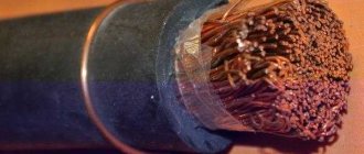
6 Flexible cores (classes 3-6)
- 6.1 Construction
- a) Flexible conductors (classes 3 to 6) shall be of annealed copper with or without metal plating, aluminum for class 3. conductors of classes 3, 4 and 5 may be made of aluminum alloy1*.
- b) All wires of each core must be of the same nominal diameter.
- c) The diameter of the core wires must not exceed the value specified in tables 5-8.
- d) Breakage or missing wires in the conductors is allowed if the electrical resistance of the conductors meets the requirements of this standard.
- e) The cores must not have burrs, cutting edges or bulging of individual wires.
- 6.2 Electrical resistance
Electrical resistance of the core at a temperature of 20 'C. determined in accordance with section 7. shall not exceed the value specified in tables 5-8.
The electrical resistance of multicore cable products with conductors of classes 4-6, twisted with a multiplicity of steps of less than 10 twist diameters, must be specified in the standards or technical specifications for cable products.
In the Russian Federation, GOST R 58019-2017 “Road rod made of aluminum alloys of grades 8176 and 8030. Technical conditions” is in force.
Table 6 Table 5 - Class 3 stranded round conductors for single-core and multi-core cables and wires
| Nominal cross-section, img | Dilmeter of core limits, mm.no more | Electrical resistance is 1 km mil at a temperature of 20 'C. Ohm. no more | ||
| Annealed copper core | Aluminum core spruce elumeeeedeo sllvoa* | |||
| Uncoated wire | Lrodeleva with metal eve we sow false tears | |||
| 0.50 | 0,33 | 39.6 | 40,7 | — |
| 0.75 | 0,38 | 25,5 | 26,0 | — |
| 1,0 | 0,43 | 21.8 | 22,3 | — |
| 1,5 | 0,53 | 14.0 | 14,3 | 23,4 |
| 2.5 | 0.69 | 7.49 | 7.63 | 12.5 |
| 4 | 0,87 | 4.79 | 4.88 | 8,00 |
| 6 | 0,65 | 3.11 | 3,17 | 5,20 |
| 10 | 0,82 | 1.99 | 2.03 | 3,33 |
| 16 | 0,65 | 1.21 | 1.24 | 2,02 |
| 25 | 0,82 | 0,809 | 0.824 | 1,35 |
| 35 | 0,69 | 0,551 | 0.562 | 0.921 |
| 50 | 0,69 | 0,394 | 0.402 | 0,658 |
| 70 | 0,69 | 0,277 | 0.283 | 0.470 |
| 95 | 0.82 | 0.203 | 0.207 | 0.338 |
| 120 | 0,79 | 0,158 | 0.161 | 0,264 |
| 150 | 0,87 | 0,130 | 0.132 | 0,211 |
| 185 | 0,87 | 0,105 | 0.107 | 0.175 |
| 240 | 0,87 | 0.0798 | 0,0814 | 0.134 |
| 300 | 0,87 | 0.0654 | 0,0666 | 0.109 |
| 400 | 0,87 | 0.0499 | 0,0509 | 0,0835 |
| 500 | 0.87 | 0.0393 | 0,0401 | 0,0657 |
9 For stranded aluminum alloy conductors having the same nominal cross-section as aluminum conductors, the value of electrical resistance shall be agreed upon between the manufacturer and the purchaser unless specified in cable standards or specifications.
Ta 6face 6 - Class 4 multi-core round conductors for single-core and multi-core cables, wires and cords
| Nominal cross-section, mm2 | Diameter of core core, mm. no more | Electrical resistance of 1 km of core at a temperature of 20 * C. Ohm. no more | ||
| Annealed copper core | Vein from burnt yalAOms/ks/eeoogo splaea* | |||
| Uncoated wire | Wire with and from ally coated | |||
| 0.05 | 0,11 | 366.6 | 383,7 | — |
| 0.08 | 0.13 | 247.5 | 254.6 | — |
| 0,12 | 0,16 | 165.3 | 170,3 | — |
| 0.20 | 0.21 | 89.1 | 91.7 | — |
| 0.35 | 0,27 | 57.0 | 58,7 | — |
| 0.50 | 0.31 | 40.5 | 41.7 | — |
| 0,75 | 0.31 | 25.2 | 25.9 | — |
| 1,0 | 0.31 | 19.8 | 20.4 | 32,9 |
| 1.5 | 0.41 | 13,2 | 13.6 | 21.9 |
| 2,5 | 0.43 | 8.05 | 8.20 | 13.4 |
| 4 | 0.53 | 4.89 | 4.99 | 8.11 |
| 6 | 0.53 | 3.28 | 3,35 | 5.44 |
| 10 | 0.53 | 2.00 | 2.04 | 3.32 |
| 16 | 0.53 | 1.21 | 1.24 | 2,01 |
| 25 | 0.53 | 0.776 | 0.792 | 1.29 |
| 35 | 0.59 | 0.547 | 0.558 | 0.908 |
| 50 | 0.59 | 0.393 | 0.401 | 0.652 |
| 70 | 0.59 | 0,281 | 0.286 | 0.466 |
| 95 | 0.59 | 0.201 | 0,205 | 0,333 |
| 120 | 0.69 | 0.162 | 0,165 | 0.269 |
| 150 | 0.69 | 0.129 | 0,132 | 0.214 |
| 185 | 0.69 | 0.104 | 0,106 | 0,173 |
| 240 | 0.69 | 0.0808 | 0.0824 | 0,134 |
| 300 | 0.69 | 0.0649 | 0.0661 | 0.108 |
| 400 | 0.69 | 0.0484 | 0.0493 | 0,0803 |
| * This requirement does not apply to cords. |
Table 7 - Flexible round conductors of class 5 for single-core and multi-core cables, wires and cords
| Nominal cross-section, mm2 | Core wire diameter. mm.no more | Electrical resistance of 1 km of core at a temperature of 20 * C. Ohm. no more | ||
| Lived from annealed copper | Core made of annealed aluminum alloy* | |||
| Uncoated wire | Industrial block with metal coating | |||
| 0.03 | 0,09 | 572.7 | 599,5 | — |
| 0.05 | 0.09 | 400.9 | 419.6 | — |
| 0.08 | 0.11 | 256.6 | 268.6 | — |
| 0.12 | 0.11 | 171,0 | 179.0 | — |
| 0.20 | 0.13 | 108.3 | 113.4 | — |
| 0.35 | 0,16 | 58.3 | 60.0 | — |
| 0.50 | 0.21 | 39.0 | 40.1 | — |
| 0.75 | 0.21 | 26.0 | 26.7 | — |
| 1.0 | 0.21 | 19.5 | 20.0 | 3Z4 |
| 1.5 | 0,26 | 13,3 | 13.7 | 2Z1 |
| 2.5 | 0.26 | 7.98 | 8.21 | 13.2 |
| 4 | 0,31 | 4,95 | 5.09 | 8.21 |
| 6 | 0.31 | 3.30 | 3.39 | 5.48 |
| 10 | 0.41 | 1.91 | 1.95 | 3.17 |
| 16 | 0.41 | 1.21 | 1.24 | 2.01 |
| 25 | 0.41 | 0.780 | 0.795 | 1.29 |
| 35 | 0.41 | 0.554 | 0.565 | 0,919 |
| 50 | 0.41 | 0.386 | 0.393 | 0.640 |
| 70 | 0,51 | 0.272 | 0,277 | 0.451 |
| 95 | 0.51 | 0.206 | 0.210 | 0,342 |
| 120 | 0.51 | 0.161 | 0,164 | 0,267 |
| 150 | 0.51 | 0.129 | 0.132 | 0,214 |
| 185 | 0,51 | 0.106 | 0.108 | 0.176 |
| 240 | 0.51 | 0.0801 | 0.0817 | 0,133 |
| 300 | 0.51 | 0.0641 | 0.0654 | 0,106 |
| 400 | 0.51 | 0.0486 | 0.04% | 0.0806 |
| 500 | 0.61 | 0.0384 | 0.0391 | 0,0637 |
| 625, 630 | 0,61 | 0,0287 | 0.0292 | 0.0476 |
| a The requirement does not apply to cords. |
Table 8 - Class 6 Flexible Round Copper Conductors for Single and Stranded Cables, Wires and Cords
| Nominal cross-section, mm3 | Diameter of core weeding, mm. no more | Electrical resistance of 1 km of core at a temperature of 20 * C. Ohm. no more | |
| Covering tray | Wire with metal locking | ||
| 0.03 | 0.06 | 669.8 | 671.5 |
| 0.05 | 0.06 | 396.9 | 397.9 |
| 0.08 | 0.06 | 267.9 | 268.6 |
| 0.12 | 0.09 | 174.4 | 174.8 |
| 0.20 | 0.11 | 113.1 | 113.4 |
| 0.35 | 0.11 | 59.5 | 59.6 |
| 0.50 | 0,16 | 39,0 | 40,1 |
| 0.75 | 0.16 | 26,0 | 26,7 |
| 1.0 | 0.16 | 19,5 | 20,0 |
| 1.5 | 0,16 | 13,3 | 13.7 |
| 2.5 | 0.16 | 7.98 | 8,21 |
| 4 | 0,16 | 4.95 | 5.09 |
| 6 | 0.21 | 3.30 | 3.39 |
| 10 | 0.21 | 1.91 | 1.95 |
| 16 | 0.21 | 1.21 | 1.24 |
| 25 | 0.21 | 0.780 | 0.795 |
| 95 | 0.31 | 0.206 | 0.210 |
| 120 | 0.31 | 0,161 | 0.164 |
| 150 | 0.31 | 0.129 | 0.132 |
| 165 | 0.41 | 0.106 | 0.108 |
| 240 | 0.41 | 0,0801 | 0,0817 |
| 300 | 0.41 | 0,0641 | 0.0654 |
Introduction
This standard is a direct application of the international standard IEC 60601-2-9-96 “Medical electrical equipment. Part 2-9. Particular safety requirements for radiotherapy dosimeters electrically coupled to radiation detectors in contact with the patient" prepared by subcommittee 62 C "Apparatus for radiotherapy, dosimetry and nuclear medicine" of technical committee IEC 62 "Medical electrical devices".
The requirements of this standard amend, supplement or replace similar requirements of the general standard GOST 30324.0, take precedence over the requirements of the general standard and are mandatory. Following the requirements, this standard provides relevant test procedures.
To change the requirements of a general standard, the following words are used:
— the word “replacement” means that a clause of a general standard is replaced in its entirety by the text of this standard;
— the word “addition” means that the text of this standard is additional to the text of the general standard;
— the word “change” means that the text of a clause of a general standard is modified by the text of this standard.
This standard highlights:
- test methods - in italics;
- terms defined in paragraph 2 of the general and present standards, in GOST IEC 60601-1-1-2011, in publications IEC 60731 and IEC 60788, in capital letters.
The numbering of sections, clauses and subclauses of this standard corresponds to the numbering of sections, clauses and subclauses of the general standard. Sections, paragraphs, subparagraphs and figures that are introduced in addition to the general standard are numbered from 101. Additional annexes are designated by the letters AA, BB, and additional paragraphs by aa), cc).
DOSIMETERS intended for use in RADIOTHERAPY with RADIATION DETECTORS electrically coupled to the device may pose a hazard to the PATIENT if the RADIATION DETECTOR is intended to be used through physical contact with the PATIENT and the DOSIMETER is not designed to meet standards for protection against electrical hazards and mechanical hazards.
a) Most DOSIMETERS used in RADIOTHERAPY are not intended for physical contact with the PATIENT; they must meet the usual safety requirements for electronic measuring instruments set out in GOST 12.2.091.
c) If the DETECTOR UNIT in the DOSIMETER is intended for physical contact with the PATIENT during RADIOTHERAPY, then the more stringent requirements of this particular standard for electrical safety, durability and disinfection apply.
c) The design of the MEASURING SYSTEM complies with the requirements of GOST 30324.0 regarding permissible LEAKAGE CURRENTS TO THE PATIENT, since it is electrically connected to the RADIATION DETECTOR.
d) If the DETECTOR UNIT and the dosimeter MEASURING SYSTEM are supplied separately or can be separated, the user must be advised which connection of the detector unit and the measuring system meets the requirements of this particular standard for use through physical contact with the patient.
It is possible, for example, that a DETECTOR UNIT connected to an unsuitable MEASURING SYSTEM (even if each individually satisfies all requirements when connected to the relevant product) may inadvertently be switched on such that its ACCESSIBLE CONDUCTIVE PARTS are at high voltage; this combination may cause a safety hazard due to the high potential for high voltage grounding through the PATIENT's body and causing incorrect readings.
This particular standard specifies the requirements to be met by MANUFACTURERS regarding the design of DOSIMETERS intended for use in RADIOTHERAPY in direct contact with the PATIENT.
CURRENT CONDUCTING CONDUCTORS FOR CABLES, WIRES AND CORDS
(IEC 60228:2004, Conductors of insulated cables, MOD)
Official publication
Moscow Standardinform 2021
Preface
The goals, basic principles and general rules for carrying out work on interstate standardization are established by GOST 1.0 “Interstate standardization system. Basic provisions" and GOST 1.2 "Interstate standardization system. Interstate standards, rules and recommendations for interstate standardization. Rules for development, acceptance, updating and cancellation"
Standard information
- 1 PREPARED by the Open Joint Stock Company “All-Russian Scientific Research. design and technological institute of the cable industry (JSC "VNIIKP") based on its own translation into Russian of the English version of the standard specified in paragraph 5
- 2 INTRODUCED by the Interstate Technical Committee for Standardization MTK 046 “Cable Products”
- 3 ADOPTED by the Interstate Council for Standardization, Metrology and Certification (protocol dated March 19, 2022 No. 138-P)
The following voted for adoption:
| Short name of the country according to MK (ISO 3164) 004-9? | Country code according to MK <ISO 3146) 004-97 | Abbreviated name of the national standardization body |
| Armenia | A.M. | CJSC “National Body for Standardization and Metrology” of the Republic of Armenia |
| Belarus | BY | State Standard of the Republic of Belarus |
| Kyrgyzstan | KG | Kyrgyzstandard |
| Russia | RU | Rosstandart |
| Tajikistan | T.J. | Tajikstandard |
| Uzbekistan | UZ | West andart |
- 4 By order of the Federal Agency for Technical Regulation and Metrology dated May 14, 2022, Ne 349-st, the interstate standard GOST 22483-2021 (IEC 60228:2004) was put into effect as a national standard of the Russian Federation from September 1, 2021.
- 5 This standard is modified from the international standard IEC 60228:2004 “Conductors of insulated cables” (MOD) by changing the content of individual structural elements and introducing additional provisions. Additional provisions and modified phrases, words, indicators and/or their meanings are highlighted in bold italics in the text. An explanation of the reasons for their inclusion is given in the introduction.
The international standard IEC 60228:2004 was developed by Technical Committee TC 20 “Electrical cables” of the International Electrotechnical Commission (IEC).
The name of this standard has been changed relative to the name of the specified international standard to bring it into compliance with GOST 1.5 (subsection 3.6)
- 6 INSTEAD POST 22483—2012 (1EC 60228:2004)
Information on the entry into force (termination) of this standard and amendments to it on the territory of the above states is published in the indexes of national standards published in these states, as well as on the Internet on the websites of the relevant national standardization bodies.
In case of revision, modification or cancellation of this standard, the relevant information will be published on the official website of the Interstate Council for Standardization, Metrology and Certification in the catalog “Interstate Standards”
€>IEC. 2004 — All rights reserved © Standardinform, design. 2021
In the Russian Federation, this standard cannot be fully or partially reproduced, replicated and distributed as an official publication without permission from the Federal Agency for Technical Regulation and Metrology
Content
- 1 area of use
- 2 Terms and definitions
- 3 Classification
- 4 Materials
- 4.1 Introduction
- 4.2 Solid aluminum conductors
- 4.3 Stranded aluminum conductors
- 5 Single-wire and multi-wire conductors
- 5.1 Single-wire and multi-wire (for large cross-sections) conductors (class 1)
- 5.2 Stranded round unsealed conductors (class 2)
- 5.3 Stranded round cores and stranded shaped cores (class 2)6
- 6 Flexible cores (classes 3-6)
- 6.1 Construction
- 6.2 Electrical resistance
- 7 Verification of compliance with the requirements of sections 5 and 6
Appendix A (mandatory) Electrical resistance measurement
Appendix B (informative) Exact formulas for determining temperature correction coefficients
Appendix C (informative) Guide to size limits for round conductors
Introduction
IEC 60228:2004 specifies requirements for the nominal conductor cross-sectional area of electrical cables, wires and cords of a wide range of types, including requirements for the number and diameter of wires and electrical resistance values.
IEC 60228:2004 sets requirements for the design of cores only for power cables and cords (see section 1), therefore it contains only core classes 1. 2. 5 and 6. Currently, a large number of cable products with core classes 3 have been developed in the CIS countries and 4. therefore, this standard has been supplemented with these classes and the word “power” has been excluded from Section 1.
The requirements for the conductors of electrical cables, wires and cords in this standard fully comply with those established in IEC 60228:2004. At the same time, this standard expands the requirements of IEC 60228:2004 to all groups of cable products, including the use of conductive cores made of aluminum alloy for classes 4 and 5, and also maintains the ranges of core sections by class: for class 1, the production of aluminum cores is retained and the possibility of manufacturing stranded cores along with single-wire ones.
Core sizes. given in this standard are established in the metric system. Currently, Canada uses the American AWG (American Wire Gauge) and kcmtl (kilo circular mils) systems for larger sizes to indicate conductor sizes and parameters, as shown below. Use in Canada of this size range is required by national electrical codes. IEC cable standards do not include cables, wires or cords with AWG/kcmil conductors.
| AWG | kcmil | ||||||
| Core size | Nominal core cross-section, us2 | Core size | Nominal conductor cross-section. м2 | Core size | Nominal conductor cross-section. mm2 | Core size | Nominal conductor cross-section. mm2 |
| — | — | — | — | 250 | 127 | 750 | 380 |
| — | — | — | — | 300 | 152 | 800 | 405 |
| 20 | 0.519 | 4 | 21.2 | 350 | 177 | 900 | 456 |
| 18 | 0.823 | 3 | 26,7 | 400 | 203 | 1000 | 507 |
| 16 | 1.31 | 2 | 33.6 | 450 | 228 | 1200 | 608 |
| 14 | 2.08 | 1 | 42.4 | 500 | 253 | 1250 | 633 |
| 12 | 3.31 | 1/0 | 53.5 | 550 | 279 | 1500 | 760 |
| 10 | 5,26 | 2/0 | 67.4 | 600 | 304 | 1750 | 887 |
| 8 | 8.37 | 3/0 | 85.0 | 650 | 329 | 2000 | 1010 |
| 6 | 13.3 | 4/0 | 107 | 700 | 355 | — | — |
f W
and
GOST 30324.2.9-2012 (IEC 60601-2-9:1996)
INTERSTATE STANDARD
MEDICAL ELECTRICAL PRODUCTS Part 2-9
Particular safety requirements for radiation therapy dosimeters electrically connected to radiation detectors in contact with the patient
Medical electrical equipment. Part 2-9. Particular requirements for the safety of patient contact dosemeters used in radiotherapy with electrically connected radiation detectors
Date of introduction - 2015—01—01
The clauses of the general standard apply, with the exception of:
Selecting the current conductor cross-section
To optimally select a conductor, power alone is not enough and you need to be able to calculate the cable cross-section by current. Its strength depends on several factors:
- length;
- temperature;
- resistivity;
- width.
If the conductor heats up, the current in it drops. In reference books, all data is indicated based on an average room temperature of eighteen degrees. To select the wiring cross-section according to the current, we again turn to the tables from the PUE. Below are tables for conductors made of different metals.
Table of cross-sections of copper conductor with PVC or rubber insulation Source m-strana.ru
Table of cross-sections of aluminum conductor with PVC or rubber insulation Source m-strana.ru
In order to calculate the cross section approximately, the current strength is divided by ten. If the required value is not available in the table, the nearest larger value is taken. However, this rule only applies to copper conductors whose maximum current does not exceed forty amperes.
In the range from forty to eighty amperes, the current is divided by eight. As for aluminum conductors, the division is made by six. This is due to the fact that in order to withstand the same loads, an aluminum wire must be thicker than a copper wire.
See also: Catalog of companies that specialize in power supply to private homes.
Why is the calculation made?
Among the reasons why tables for selecting cross-sections in cables by power are used are the following:
- Compliance with safety rules.
- Compliance with the wiring conditions.
- Providing residential premises with a stable flow of electrical energy.
- Avoiding unnecessary investments.
- Formation of knowledge about wiring in your home or apartment.
If you are completely confident in fulfilling all these factors, then you will be able to avoid unexpected breakdowns and subsequent repairs. Even if incorrectly selected indicators of wire cross-sections for currents and power only lead to a communications malfunction, then in order to restore the devices’ access to operation, you will encounter the following problems:
- Removing plaster or wallpaper from the places where the wiring lies;
- Purchasing new cables and replacing old ones;
- In case of breakdown of electrical appliances, replace or repair them.
From this we conclude that it is better to spend a little time at the very beginning than to burden yourself with unnecessary worries later.