Electrical networks entangle the walls of houses like a web. Without electricity, the life of a modern person is simply impossible. When laying new wiring or performing repairs, you must carefully comply with the accepted requirements. They are the key to the reliability and safety of the electrical network. One of the indicators taken into account when choosing wiring characteristics is the cross-section. When determining it, the permissible current for copper wires is taken into account. It shows the amount that a wire can pass without heating for a certain time.
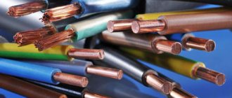
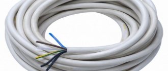
stranded copper wires
Allowable and operating current density
The permissible current for copper wires is the most important indicator when determining the cable cross-section. Its value is taken based on the requirements of the PUE. For copper, the permissible continuous current is 6-10 A per square millimeter. A value of 6 A is working and can be used for a long time. An increased load of 10 A is called permissible, it can be used for a short time.
Wire insulation is of great importance. Read here about which insulation is better.
To understand why such restrictions are introduced, we suggest comparing the operation of a cable with a pipeline transporting water or gas. The walls of the pipe limit the spread of substances, just as a conductor prevents the loss of electrons. If the cross-sectional area of the wire is selected incorrectly, the following options are possible:
- A narrow channel leads to an increase in particle density. This leads to overheating of the insulation and its melting. The consequence of this is an increased fire danger.
- A wide channel has fewer disadvantages. It transports current without overheating. However, overestimated cable parameters contribute to an increase in the cost of the electrical network.
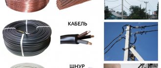
Aluminum and copper wires are used for electrical wiring. It is recommended to construct internal networks from copper, which has many advantages:
- does not corrode;
- soft but durable;
- has increased conductivity.
The only disadvantage of copper is its high cost. To choose the right wiring, you will need to take into account such an indicator as the permissible current density for a copper wire. Only with this approach can it be possible to eliminate excessive heating of electrical network elements and voltage drops above permissible values. In addition, correctly selected thickness will ensure reliable operation of the network and protect it from mechanical damage.
Current measuring device
Calculation of permissible current for heating cores
If a conductor of a suitable cross-section is selected, this will eliminate voltage drop and overheating of the line. Thus, the cross-section determines how optimal and economical the operating mode of the electrical network will be. It would seem that you can simply take and install a cable with a huge cross-section. But the cost of copper conductors is proportional to their cross-section, and the difference when installing electrical wiring in just one room can amount to several thousand rubles. Therefore, it is important to be able to correctly calculate the cable cross-section: on the one hand, you guarantee the safe operation of the network, on the other hand, you will not spend extra money on purchasing an overly “thick” conductor.
To select the wire cross-section, two important criteria must be taken into account - permissible heating and voltage loss. Having received two values for the cross-sectional area of the conductor using different formulas, choose the larger value, rounding it to the standard. Overhead power lines are especially sensitive to voltage loss. At the same time, for underground lines and cables placed in corrugated pipes, it is important to take into account the permissible heating. Thus, the cross-section should be determined depending on the type of wiring.
Permissible heating temperatures of current-carrying cable cores.
Id - permissible load on the cable (heating current). This value corresponds to the current flowing through the conductor over a long period of time. In the process of this, a set, long-term permissible temperature (Td) appears. The calculated current strength (Ip) must correspond to the permissible current (Id), and to determine it you need to use the formula:
- Iр=(1000*Pн*kз)/√(3*Un*hд*cos j),
Where:
- Pn — rated power, kW;
- Kz - load factor (0.85-0.9);
- Un — rated voltage of the equipment;
- hd - equipment efficiency;
- cos j - equipment power factor (0.85-0.92).
It turns out that for any long-term permissible current flowing through the conductor, there corresponds a specific value of the established, long-term permissible heating temperature. It is important to neutralize the influence of other environmental factors. The cable current directly depends on the material from which the insulation is made, the laying method, the cross-section and material of the cores in the conductor.
Even if we take into account the same current values, the thermal output will be different depending on the ambient temperature. The lower the temperature, the more efficient the heat transfer.
Cable correction factors depending on ambient temperature
Temperatures differ depending on the region and time of year, so in the PUE you can find tables for specific values. If the temperature differs significantly from the calculated one, correction factors will have to be used. The base temperature indoors or outdoors is 25 degrees Celsius. If the cable is laid underground, the temperature changes by 15 degrees Celsius. However, it is underground that it remains constant.
Calculation of wire cross-section
The area formed by cutting the current-carrying core is called the cable cross-section. Most often it has a round shape and consists of one or more wires. It is selected based on the expected load, using special tables. Experienced electricians often rely on approximate values: for sockets a cable of 1.5-2.5 square millimeters is enough, for lighting 1-1.5 is enough. However, such an assumption is not always justified. If a large amount of powerful equipment is to be installed in the room, you will need to make a simple calculation.
Which wires are best to use for wiring in an apartment. Great comparison article here.
The main indicator influencing the desired value is the current load. It represents the current of the copper wire (I) that will pass through it and will not cause heating above 60 degrees. To find it, you need to sum up the power of all electrical appliances (P) that will be installed in the room. Further calculations are based on the simplest formulas from the physics course:
- For a 220 V network (U): I=(P*KИ)/(U*cos φ), in the formula Ki is a coefficient that takes into account the possibility of simultaneously turning on all electrical appliances in the house (taken equal to 0.75); cos φ ‑ for a household network take 1.
- For a 380 V network (U): I=P/(1.73*U*cos φ).
The unit of force is one ampere. The obtained result is used to select parameters in special tables.
Often the calculated value does not coincide with the tabulated value. Then it is increased to the next larger one.
When working with tables, you should pay attention that the choice of wire is influenced by its location (ground or air), material (copper or aluminum), and number of cores (one or more).
Wire marking
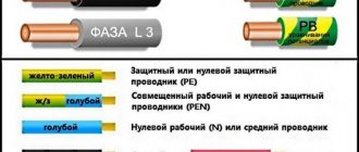
In order not to get lost in the variety of cable products, it is recommended that you familiarize yourself with their markings. The letters and numbers contain important information for a specialist that allows you to correctly select and use the element. For PVC wires (with polyvinyl chloride) or rubber insulation, the presence of the first letter A indicates the material (A - aluminum, no letter - copper). Next comes the letter Ш (cord) or P (wire). Insulation material is indicated using the following abbreviations:
- B - polyvinyl chloride;
- R – rubber;
- N – nerite rubber;
- P – polyethylene.
Additionally, there may be markings that help determine the quality of the wire: P - flat, G - flexible, C - connecting. For PV brand cables, the degree of flexibility is often indicated in numbers (1, 2, 4). The higher the number, the more flexible the wire. There is also often information about the number of cores and their area. It is recommended to consult a specialist if in any doubt. Also, we must not forget about the tables that show the limit values for the current use of copper wire. Neglect of basic rules leads to incorrect operation of the equipment, often causing a fire.
Odds
There are certain conditions under which the current inside the wiring can increase or decrease. For example, in open electrical wiring, when the wires are laid along walls or ceilings, the current strength will be higher than in a closed circuit. This is directly related to the ambient temperature. The larger it is, the more current this cable can carry.
Attention! All of the above listed PUE tables are calculated under the condition that the wires are operated at a temperature of +25C with the temperature of the cables themselves not exceeding +65C.
That is, it turns out that if several wires are laid at once in one tray, corrugation or pipe, then the temperature inside the wiring will be increased due to the heating of the cables themselves. This leads to the fact that the permissible current load is reduced by 10-30 percent. The same applies to open wiring inside heated rooms. Therefore, we can conclude: when calculating the cable cross-section depending on the current load at elevated operating temperatures, you can choose wires of a smaller area. This is, of course, a good saving. By the way, there are also tables of reducing coefficients in the PUE.
There is one more point that concerns the length of the electrical cable used. The longer the wiring, the greater the voltage loss in the sections. Any calculations use a loss of 5%. That is, this is the maximum. If the losses are greater than this value, then the cross-section of the cable will have to be increased. By the way, it’s not difficult to independently calculate current losses if you know the wiring resistance and current load. Although the best option is to use the PUE table, which establishes the relationship between load torque and losses. In this case, the load torque is the product of the power consumption in kilowatts and the length of the cable itself in meters.
Let's look at an example in which an installed cable 30 mm long in an alternating current network with a voltage of 220 volts can withstand a load of 3 kW. In this case, the load moment will be equal to 3*30=90. We look at the PUE table, which shows that losses of 3% correspond to this moment. That is, it is less than the nominal value of 5%. What is acceptable. As mentioned above, if the calculated losses exceeded the five percent barrier, then it would be necessary to purchase and install a cable of a larger cross-section.
Attention! These losses greatly affect lighting with low-voltage lamps. Because at 220 volts 1-2 V is not reflected much, but at 12 V it is immediately visible.
Currently, aluminum wires are rarely used in wiring. But you need to know that their resistance is 1.7 times greater than that of copper ones. And that means their losses are just as many times greater.
As for three-phase networks, the load torque here is six times greater. This depends on the fact that the load itself is distributed over three phases, and this is a corresponding exponential increase in torque. Plus a double increase due to the symmetrical distribution of power consumption across phases. In this case, the current in the zero circuit must be zero. If the phase distribution is asymmetrical, and this leads to an increase in losses, then you will have to calculate the cable cross-section for the loads in each wire separately and select it according to the maximum calculated size.
Open and closed wiring
Electrical wiring can be of two types:
- closed;
- open.
In most cases, hidden installation is used for apartments. Using a hammer drill or wall chaser, special recesses are created in the wall or ceiling into which the cable is laid. Additionally, it can be placed in corrugated tubes or sleeves. Having hidden the cable, the recesses should be sealed with plaster. The only acceptable option for modern hidden wiring is copper conductors. In this case, you should consider in advance the potential expansion of the network or the process of partial replacement of its components. Ideally, you should use flat wires.
Laying hidden wiring in grooves
Open electrical wiring involves placing the cable along surfaces. Mainly flexible conductors with a round cross-section are used. They are placed in cable ducts or passed through corrugations. When calculating the load, the cable laying method must be taken into account.
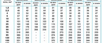
Long-term permissible load currents, A
| Nominal cross-section, mm2 | Section (aluminium/steel, mm2) | AC | |
| outdoors | indoors | ||
| 10 | 10/1,8 | 84 | 53 |
| 16 | 16/2,7 | 111 | 79 |
| 25 | 25/4,2 | 142 | 109 |
| 35 | 35/6,2 | 175 | 135 |
| 50 | 50/8 | 210 | 165 |
| 70 | 70/11 | 265 | 210 |
| 95 | 95/16 | 330 | 260 |
| 120 | 120/19 120/27 | 390 375 | 313 — |
| 150 | 150/19 150/24 150/34 | 450 450 450 | 365 365 — |
| 185 | 185/24 185/29 185/43 | 520 510 515 | 430 425 — |
| 240 | 240/32 240/39 240/56 | 605 610 610 | 505 505 — |
| 300 | 300/39 300/48 300/66 | 710 690 680 | 600 585 — |
| 330 | 330/27 | 730 | — |
| 400 | 400/22 400/51 400/64 | 830 825 860 | 713 705 — |
| 500 | 500/27 500/64 | 960 945 | 830 815 |
| 600 | 600/72 | 1050 | 920 |
Current load on the cable: how to calculate the cross-section
The total amount of current moving through a conductor depends on several characteristics: length, width, resistivity and temperature. An increase in temperature is accompanied by a decrease in current. Any reference information that you find in the PUE tables is usually provided for a room temperature of 18 degrees Celsius.
In addition to the electric current, you need to know the conductor material and voltage. The simplest calculation of cable cross-section based on permissible current is to divide its value by 10. If, when studying the table, you do not find the required value, then look for the nearest, slightly larger value. This option is possible for copper wires, and the permissible current is 40 A or less. In the range of 40-80 A, the permissible current should be divided by 8. For aluminum wires, the value is divided by 6. The reason for this was indicated at the end of the previous section.
Permissible current load on the cable
How to choose the right input wire for an apartment?
The value of the rated current on the input cable to the apartment depends on how many consumers are connected. The table shows the necessary devices and their power.
| electrical appliance | Rated power, kW |
| TV | 0,18 |
| Boiler | 2-6 |
| Fridge | 0,2-0,3 |
| Oven | 2-5 |
| Vacuum cleaner | 0,65-1 |
| Electric kettle | 1,2-2 |
| Iron | 1,7-2,3 |
| Microwave | 0,8-2 |
| Computer | 0,3-1 |
| Washing machine | 2,5-3,5 |
| Lighting system | 0,5 |
| Total | 12,03-23,78 |
I = P∙Ki/(U∙cos φ), where Ki = 0.75 – simultaneity coefficient.
For most electrical appliances that are active loads, the power factor cos φ = 1. For fluorescent lamps, electric motors of a vacuum cleaner, washing machine, etc., it is less than 1 and must be taken into account.
The long-term permissible current for the devices given in the table will be I = 41 - 81 A. The value turns out to be quite impressive. When purchasing a new electrical appliance, you should always think carefully about whether your apartment network will support it. According to the table for open wiring, the cross-section of the input wire will be 4-10 mm2.
Here you also need to take into account how the apartment load will affect the general building load. It is possible that the housing office will not allow connecting so many electrical appliances to the entrance riser, where a busbar (copper or aluminum) passes through the distribution cabinets under each phase and neutral. They simply won’t be able to handle the electricity meter, which is usually installed in a switchboard on the landing. In addition, the fee for excess consumption of electricity will increase to impressive sizes due to increasing coefficients.
If wiring is done for a private house, then the power of the outlet wire from the main network must be taken into account. The commonly used aluminum wire SIP-4 with a cross-section of 12 mm2 may not be enough for a heavy load.
Wiring cross-sectional area
The shape of the wire is made in the form of a circle, square, rectangle or triangle. Apartment wiring has a predominantly round cross-section. The copper busbar is usually installed in a distribution cabinet and can be rectangular or square.
The cross-sectional areas of the cores are determined by the main dimensions measured with a caliper:
- circle – S = πd2 / 4;
- square – S = a2;
- rectangle – S = a * b;
- triangle – πr2 / 3.
The following notations are used in the calculations:
- r – radius;
- d – diameter;
- b, a – width and length of the section;
- π = 3.14.
Permissible long-term stress for wires, cords and cables with rubber or plastic insulation
1.3.10. Permissible long-term currents for wires with rubber or polyvinyl chloride insulation, cords with rubber insulation and cables with rubber or plastic insulation in lead, polyvinyl chloride and rubber sheaths are given in Table. 1.3.4-1.3.11. They are accepted for temperatures: cores 65, ambient air 25 and ground 15°C.
When determining the number of wires laid in one pipe (or cores of a stranded conductor), the neutral working conductor of a four-wire three-phase current system, as well as grounding and neutral protective conductors are not taken into account.
The data contained in the table. 1.3.4 and 1.3.5 should be applied regardless of the number of pipes and the location of their installation (in the air, floors, foundations).
Permissible long-term currents for wires and cables laid in boxes, as well as in trays in bundles, must be accepted: for wires - according to table. 1.3.4 and 1.3.5 as for wires laid in pipes, for cables - according to table. 1.3.6-1.3.8 as for cables laid in the air. If the number of simultaneously loaded wires is more than four, laid in pipes, boxes, and also in trays in bundles, the currents for the wires should be taken according to the table. 1.3.4 and 1.3.5 as for wires laid openly (in the air), with the introduction of reduction factors of 0.68 for 5 and 6; 0.63 for 7-9 and 0.6 for 10-12 conductors.
For secondary circuit wires, reduction factors are not introduced.
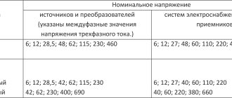
1.3.22. Permissible continuous currents for bare wires and painted tires are given in table. 1.3.29-1.3.35. They are taken based on the permissible heating temperature of 70°C at an air temperature of 25°C.
| Wire brand | PA500 | Pa6000 |
| Current, A | 1340 | 1680 |
1.3.23. When rectangular busbars are arranged flat, the currents given in table. 1.3.33, must be reduced by 5% for tires with a stripe width of up to 60 mm and by 8% for tires with a stripe width of more than 60 mm.
1.3.24. When choosing buses of large sections, it is necessary to choose the most economical design solutions in terms of throughput, ensuring the least additional losses from the surface effect and the proximity effect and the best cooling conditions (reducing the number of strips in the package, rational design of the package, the use of profile tires, etc.) .