Using our calculator, you can calculate the cable cross-section by power (load) or current, taking into account the line length with a minimum error. The main indicators are the conductor material (copper, aluminum), voltage (220 V / 380 V) and load/current in the circuit. The method of laying the cable affects the cross-section of the conductor - closed cables require a larger cross-section, since due to limited heat transfer the metal heats up more. After carrying out the classic calculation for power/current, an additional calculation is carried out for the length of the conductor - the largest of the resulting pair of values is selected. The theoretical basis for the calculation is presented below in the form of formulas and tables. You may only be interested in the voltage loss calculator.
Related regulatory documents:
- PUE-7 “Rules for electrical installations”
- SP 76.13330.2016 “Electrical devices”
- GOST R 50571.5.52-2011/IEC 60364-5-52:2009 “Low-voltage electrical installations. Selection and installation of electrical equipment"
- GOST 31946-2012 “Self-supporting insulated and protected wires for overhead power lines”
- GOST 31947-2012 “Wires and cables for electrical installations for rated voltage up to 450/750 V”
- GOST 6323-79 “Wires with polyvinyl chloride insulation for electrical installations”
- GOST 31996-2012 “Power cables with plastic insulation for a rated voltage of 0.66; 1 and 3 kV"
- GOST 433-73 “Power cables with rubber insulation”
How to calculate cable cross-section by power?
First step . The total power of all electrical appliances that can be connected to the network is calculated:
Psum = (P1 + P2 + .. + Pn) × Kс
- P1, P2 .. – power of electrical appliances, W;
- Kc – demand coefficient (probability of simultaneous operation of all devices), default is 1.
Second step . Then the rated current in the circuit is determined:
I = Psum / (U × cos ϕ)
- Psum – total power of electrical appliances;
- U – network voltage;
- cos ϕ – power factor (characterizes power losses), default is 0.92.
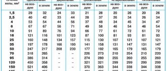
Third step . At the last stage, tables are used in accordance with the PUE (Electrical Installation Rules).
Table of copper cable cross-section by current according to PUE-7
| Conductor cross-section, mm2 | Current, A, for wires laid | |||||
| open | in one pipe | |||||
| two single-core | three single-core | four single-core | one two-wire | one three-wire | ||
| 0.5 | 11 | — | — | — | — | — |
| 0.75 | 15 | — | — | — | — | — |
| 1 | 17 | 16 | 15 | 14 | 15 | 14 |
| 1.2 | 20 | 18 | 16 | 15 | 16 | 14.5 |
| 1.5 | 23 | 19 | 17 | 16 | 18 | 15 |
| 2 | 26 | 24 | 22 | 20 | 23 | 19 |
| 2.5 | 30 | 27 | 25 | 25 | 25 | 21 |
| 3 | 34 | 32 | 28 | 26 | 28 | 24 |
| 4 | 41 | 38 | 35 | 30 | 32 | 27 |
| 5 | 46 | 42 | 39 | 34 | 37 | 31 |
| 6 | 50 | 46 | 42 | 40 | 40 | 34 |
| 8 | 62 | 54 | 51 | 46 | 48 | 43 |
| 10 | 80 | 70 | 60 | 50 | 55 | 50 |
| 16 | 100 | 85 | 80 | 75 | 80 | 70 |
| 25 | 140 | 115 | 100 | 90 | 100 | 85 |
| 35 | 170 | 135 | 125 | 115 | 125 | 100 |
| 50 | 215 | 185 | 170 | 150 | 160 | 135 |
| 70 | 270 | 225 | 210 | 185 | 195 | 175 |
| 95 | 330 | 275 | 255 | 225 | 245 | 215 |
| 120 | 385 | 315 | 290 | 260 | 295 | 250 |
| 150 | 440 | 360 | 330 | — | — | — |
| 185 | 510 | — | — | — | — | — |
| 240 | 605 | — | — | — | — | — |
| 300 | 695 | — | — | — | — | — |
| 400 | 830 | — | — | — | — | — |
Table of cross-section of aluminum cable by current according to PUE-7
| Conductor cross-section, mm2 | Current, A, for wires laid | |||||
| open | in one pipe | |||||
| two single-core | three single-core | four single-core | one-two-core | one three-wire | ||
| 2 | 21 | 19 | 18 | 15 | 17 | 14 |
| 2.5 | 24 | 20 | 19 | 19 | 19 | 16 |
| 3 | 27 | 24 | 22 | 21 | 22 | 18 |
| 4 | 32 | 28 | 28 | 23 | 25 | 21 |
| 5 | 36 | 32 | 30 | 27 | 28 | 24 |
| 6 | 39 | 36 | 32 | 30 | 31 | 26 |
| 8 | 46 | 43 | 40 | 37 | 38 | 32 |
| 10 | 60 | 50 | 47 | 39 | 42 | 38 |
| 16 | 75 | 60 | 60 | 55 | 60 | 55 |
| 25 | 105 | 85 | 80 | 70 | 75 | 65 |
| 35 | 130 | 100 | 95 | 85 | 95 | 75 |
| 50 | 165 | 140 | 130 | 120 | 125 | 105 |
| 70 | 210 | 175 | 165 | 140 | 150 | 135 |
| 95 | 255 | 215 | 200 | 175 | 190 | 165 |
| 120 | 295 | 245 | 220 | 200 | 230 | 190 |
| 150 | 340 | 275 | 255 | — | — | — |
| 185 | 390 | — | — | — | — | — |
| 240 | 465 | — | — | — | — | — |
| 300 | 535 | — | — | — | — | — |
| 400 | 645 | — | — | — | — | — |
In the electrical installation rules of the 7th edition there are no tables of cable cross-section by power , there is only data on current strength. Therefore, when calculating sections using load tables on the Internet, you risk getting incorrect results.
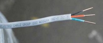
Difference between cable and cord
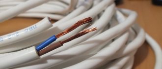
According to the definition, cords are flexible wiring that includes several elastic strands - intertwined wires insulated with a non-metallic sheath. The products are designed for movable connection. The difference between the cords is the number of cores: there are multi-core and two-core products; the more threads in the core per unit section, the more flexible the conductor. There are flexible cores with increased ductility used to create cords.
The flat shape and minimum cross-section of the cores (1.5 mm2), use in household electrical wiring are the main indicators that allow you to determine how cords differ from cables and wires. Multi-core options are more common, but for electrical appliances that do not require special grounding, two-core cords are quite suitable.
Insulation
The flexible cord cores are covered with polymer insulation and enclosed in one protective casing made of soft plastic or rubber.
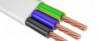
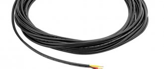
An electrical cable is formed by several wires protected by a common insulation (PVC, rubber, plastic). Depending on the application, many manufacturers tend to equip the cable with reinforced protective covers, and the wire or cord is hidden under a light sheath.
Only the cable may have additional armor made of lead, aluminum or steel wire/tape, indicated in the marking.
Marking
KVVG cable
Depending on the purpose and type of insulation in electrical engineering, the following cable markings are found:
- Power options in PVC insulation - NYM, AVVG, VVG.
- Flexible conductors in a rubber casing - KG.
- Control cables - KVVG.
- Power armored products - AVBShv, VBBShvng.
- Information and radio frequency - FTP, UTP, RG, SAT, RK, KVK-V, KVK-P.
- Fire, alarm products: KPSng, KPSEng, KSVV, KSPV, KTSPPEP.
- Heat-resistant - RKGM.
Ball screw wire
Among the common brands of cords are: Ball screw, ShVVP, ShTLP. The first option is suitable for connecting electronic equipment, apartment lamps and climate control equipment (fans, ionizers), subject to slight mechanical deformations.
SHVVP is a stranded cord with copper stranded conductors insulated with polyvinyl chloride plastic. The vinyl shell prevents the spread of fire in case of fire.
SHTLP - telephone conductor. The cord is linear, contains copper stranded conductors in polyethylene film with PVC insulation.
Conditions of use
The service life of the SHVVP cord under normal conditions is a maximum of 6 years.
The softness and flexibility of the cord determines its widespread use in everyday life, when connecting household appliances. For fixed installation, monolithic cables (power, control, control and communications, radio frequency) are preferred.
Life time
The service life of the cable depends on the technical characteristics and operating conditions. For example, power-type products have been used for 30 years at temperatures of −50…+50°C. When laid outdoors and in trenches, the control cable works for more than 15 years, in rooms, tunnels, and channels - 25 years. Under normal conditions, the SHVVP cord will last a maximum of 6 years.
The constant operating voltage for a cable varies between 25-70 kV and more, for a cord - 380 V.
Selecting cable cross-section based on current strength
First step . The calculation is carried out in exactly the same way, that is, first the total power of all electrical appliances that can be connected to the network is calculated:
Psum = (P1 + P2 + .. + Pn) × Kс
- P1, P2 .. – power of electrical appliances, W;
- Kc – demand coefficient (probability of simultaneous operation of all devices), default is 1.
Second step . Then the rated current in the circuit is determined (for direct and alternating current (1-phase/3-phase), respectively):
I = Psum / UI = Psum / (U × cos ϕ) I = Psum / (U × cos ϕ × √3)
- Psum – total power of electrical appliances;
- U – network voltage;
- cos ϕ – power factor (characterizes power losses), default is 0.95.
Third step . At the last stage, the same tables are used, according to the PUE (Electrical Installation Rules), which are located above.
Rules for marking live parts according to the PUE
To ensure clarity, simplicity and ease of recognition of individual parts of the electrical network, in accordance with clause 1.1.30 of the PUE, all electrical installations must have an alphanumeric and color designation. Moreover, the presence of one of these designations does not eliminate the need for the other.
And the only relaxation is the possibility of applying a designation not along the entire length of the conductor, but only at the connection points, as shown in the video.
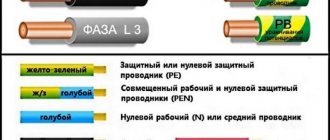
Wire color coding
Marking wires by color is the most visual and allows you to quickly determine the purpose of any wire. This marking can be done by selecting wires with the appropriate core insulation color, by applying paint to the busbars, or by painting or applying special colored tape at the core junctions.
Moreover, the paint on the tires may not be applied along the entire length, but only at the connection points or at the ends of the tires.
Designation of phase wires
So:
- If we talk about the color designation of wires and cables, then we should start with the phase conductors. According to clause 1.1.30 of the PUE in a three-phase network, phase conductors must be marked in yellow, green and red. This is how phases A, B and C are designated respectively.
- The instructions for a single-phase electrical network suggest the designation of the phase wire in accordance with the color of which it is a continuation. That is, if a phase conductor is connected to phase “B” of a three-phase network, then it should be green.
Note! In a single-phase network in an apartment or house, you often do not know which phase your phase wire is connected to. In order to comply with GOST, you do not have to find out this at all. It is enough to designate the phase conductor with any of the proposed colors. After all, for a single-phase lighting network, it does not matter at all which phase your conductor is connected to. The only exception is the lighting network, which uses two different phase conductors.
- As for the neutral conductors, they should be blue in color. Moreover, the color of the neutral core does not depend on the three-phase, two-phase or single-phase network in front of you. It is always indicated in blue.
- Wire markings with a yellow-green stripe indicate a protective conductor. It is connected to the housing of electrical appliances and provides safety from electric shock if the insulation of electrical equipment is damaged.
Designation of neutral and protective conductors
- If the neutral and protective conductors are combined, then according to clause 1.1.29 of the PUE, such a wire core should have a blue color with yellow-green stripes at its ends. To make such markings with your own hands, you just need to take a blue wire and mark it with paint on its end seals or use colored electrical tape for this.
- As for DC networks, the positive core of a wire or bus should be indicated in red, and the negative core in blue. In this case, the designation of the neutral and protective conductors corresponds to the markings in alternating current networks.
Letter marking of wires
But color marking of wires is not always convenient. In switchboards, switchgears and on diagrams, the letter designation is much more convenient. It must be used in conjunction with the color designation.
So:
- The letter marking of phase wires in a three-phase network corresponds to their colloquial designation - phase “A”, “B” and “C”. For a single-phase network it should be the same, but this is not always convenient. Moreover, it is not always possible to reliably determine which phase exactly. Therefore, the designation “L” is often used.
Note! Clause 1.1.31 of the PUE standardizes not only the letter and color designation of conductors, but also their location. So for a three-phase network with vertical busbars, phase “A” should be the topmost, and phase “C” the bottom. And with a horizontal arrangement of conductors, the phase “C” closest to you should be, and the most distant phase “A”.
- If the wires are marked in the panel, then the symbol “N” indicates the neutral wire.
- The letter designation “PE” is used to designate the protective conductor. In addition, the grounding sign is often used, but the fact is that it cannot always accurately indicate the network diagram.
The photo shows a grounding sign
- The fact is that you may come across the designation “PEN”. It denotes the combination of the neutral and protective conductors. This is possible in TN-CS systems, which we discussed in one of our previous articles.
- But the marking of DC electrical wires is carried out with the symbolisms “+” and “―”. Which respectively means positive and negative wire. For direct current there is another difference. The zero core is designated by the symbol “M”, which is sometimes misleading.
DC marking