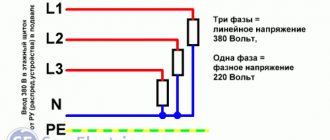
Why do you need to consider phase order?
The sequence of alternations plays a significant role in such situations:
- When connected in parallel, a number of devices (transformers, generators and other electrical machines) can be connected in parallel operation to increase the reliability of the system or to provide a greater power reserve. But, in case of incorrect connection, a short circuit will occur due to the connection of opposite phases.
- When connecting a three-phase meter - since its operation is based on the coincidence of phases with the corresponding terminals of the device, then if the connection is not correct, a failure and spontaneous movement may occur in the absence of any load. Because of this, such a connection of the electric meter will lead to the need for the consumer to pay for kilowatts that he did not consume.
- When the engine is turned on, the sequence of phases in the network determines the direction of rotation of the engine for the electric machine. In the absence of correct phasing, the direction of movement of the elements mechanically connected to the rotor will also change. This could result in a disruption of the technological process or a threat to the lives of personnel.
In order to prevent other mismatches, in practice, an interleaving check is performed and protection is installed.
A short introduction
A story about the installation of electrical equipment, namely two oil transformers, caught my eye. The work was completed successfully. As a result, there was the following power supply scheme. Actually the transformers themselves, input switches, sectional disconnectors, two bus sections. According to the installers, the commissioning work was completed successfully. They started switching on both transformers for parallel operation and got a short circuit. Naturally, the installers claimed that they had checked the phase rotation from both sources and everything matched. But not a word was said about phasing. But in vain! Now let's take a closer look at what went wrong.
What is phase alternation
It is known that a three-phase network consists of opposite phases. They are called ABC. According to theory, we know that the phase sinusoids are shifted relative to each other by one hundred and twenty degrees.
There are six different alternating orders, either reverse or direct. Reverse - CBA, ACB, BAC, direct - CAB, BCA, ABC.
To check the phase rotation order, use a phase indicator. Let's look at the method of checking with a phase indicator.
How is the check carried out?
The phase indicator structurally includes a disk with black and white marks for reading readings, and 3 windings. In operating mode, the disk should rotate.
We connect three wires from a voltage supply device with three phases to the output terminals. We turn on the device with the button located on the side panel.
The disk should start spinning. When rotation occurs along the direction of the arrow displayed on the device, the phase alternation is direct and refers to the corresponding type CAB, ABC or BCA.
If the rotation occurs against the direction of the arrows, the phase sequence is reversed. Corresponds to ABC, CBA or BAC.
Let's remember the situation with the installation of transformers, described at the beginning of the article. The electricians just determined the phase rotation, the order coincided.
But they didn't check the phasing. And it is impossible to carry out this check using a phase indicator.
When connecting, opposite phases were connected. To understand which phase it is and where it is located, you need a combined electrical measuring instrument or an oscilloscope.
A combined measuring device measures the magnitude of the phase-to-phase voltage of various power sources. When the value is zero – they are of the same name.
In the case when the value corresponds to a linear indicator - opposite. This is a fairly simple and effective method.
When using an oscilloscope, the lag and phase determination are determined by the oscillogram readings, but this method is not practical due to the complex methodology and high cost of the device.
Operating procedure
The work is carried out in the following order by a licensed RTN electrical laboratory:
- checking the absence of voltage on the equipment being put into operation;
- the cable is disconnected from the busbars;
- one of the conductor cores is grounded;
- the insulation resistance of the conductor cores relative to the ground is measured;
- the conductor is marked, the resistance of which relative to the ground will be zero;
- phasing of the remaining cable cores is performed;
- the cable is connected to the switchgear according to the marking;
- a dialing operation is performed;
- phasing is performed under voltage. The check is carried out between the phases of the same name and the others. If there is no voltage between like phases, but there is voltage between opposite phases, then such a cable is put into operation, and therefore the switchgear.
The Perestroika MSK company has all the necessary permits and specialists who will perform the service of checking the phasing of switchgear and electrical equipment in the shortest possible time at the best prices in Moscow and Moscow Region. The customer is issued a document certifying the quality of the work performed.
What is phase rotation?
Phase alternation should be understood as the sequence in which the voltage increases in each of them. In all three-phase circuits, the voltage is a sinusoidal curve. In each line the voltage differs by 120º from the others.
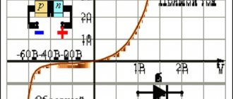
Rice. 1. Voltage in three-phase network
Peculiarities
To reduce the likelihood of phase overload, the load is distributed evenly across phases. Failure to comply with this condition, as well as burnout of the “zero” conductor or its poor contact, will lead to a difference in voltage on the phase conductors, up or down.
Thus, converted single-phase power (220 V) will lead to malfunction of electrical consumers connected to it. This will happen due to the fact that some devices will receive an increased voltage (240-270 V), while others will receive a reduced voltage (160-200 V).
Important! If the load is unevenly distributed across phases, on meters that are not sensitive to distortions, there will be an increased consumption of electricity.
What is phase alternation?
As you know, in a three-phase network there are three opposite phases. Conventionally, they are designated as A, B and C. Remembering the theory, we can say that the phase sinusoids are shifted relative to each other by 120 degrees. So, there can be six different alternation orders in total, and they are all divided into two types - direct and reverse. The following order is considered direct alternation - ABC, BCA and CAB. The reverse order will be CBA, BAC and DIA, respectively.
To check the order of phase alternation, you can use a device such as a phase indicator. We have already talked about how to use the phase indicator. Let's look specifically at the sequence of checking with the FU 2 device.
Direct and reverse phase rotation
Three-phase alternating current is graphically represented by three phases in the form of alternating sinusoids on the X-axis, shifted relative to each other by 120°. The first sine wave can be represented as phase A, the next sine wave as phase B, shifted 120° relative to phase A, and the third phase C, also shifted 120° relative to phase B.
Graphic display of phase shift for 120° three-phase network
If the phases have the order ABC, then this sequence of phases is called direct alternation. Consequently, the order of the SVA phases will mean reverse alternation. In total, three direct alternations of phases ABC, BCA, CAB are possible. For reverse phase rotation, the order will look like CBA, BAC, ACB.
You can check the phase rotation of a three-phase network using a phase indicator FU - 2. It is a small case on which there are three clamps for connecting three phases of the network, an aluminum disk with a black dot on a white background and three windings. Its operating principle is similar to that of an asynchronous electric motor.
If you connect the phase indicator to three phases and press the button on the housing, the disk will begin to rotate in one direction. When the rotation of the disk coincides with the arrow on the body, then the phase indicator shows direct phase rotation; rotation of the disk in the opposite direction indicates reverse phase rotation.
Electrical circuit of the phase indicator FU-2
In what cases is it necessary to know the order of phase rotation? Firstly, if the house is connected to a three-phase network and an induction electric meter is installed, then direct phase rotation must be observed on it. If such an electric meter is connected incorrectly, it may self-propel, which will give incorrect readings in the direction of increasing electricity consumption.
Also, if asynchronous electric motors are used in the house, the direction of rotation of the rotor will depend on the order of phase alternation. By changing the phase sequence on an asynchronous electric motor, you can change the direction of rotation of the rotor in the desired direction.
Protection against alternation violation
To protect electrical equipment from incorrect rotation, a phase control relay is used in practice. This relay is configured to operate the engine or other device when it is connected directly. If due to some malfunction or incorrect connection the alternation is disrupted, the three-phase relay will immediately turn off the device. His work is based on the analysis of three-phase currents and voltages and subsequent monitoring of these parameters.
The connection can be made through current transformers or directly, depending on the model and voltage class of the network. Such protection has found wide application when connecting induction-type meters, electrical machines and other high-precision equipment.
What is it for?
Phase and voltage control relay is a device that is necessary when connecting equipment to a system with three phases, as well as in situations where it is important to maintain correct alternation
In practice, the product is used when equipment is frequently transferred, when changing the phasing may cause damage or incorrect operation.
A striking example is a screw-type compressor, the incorrect connection of which and switching on for more than five seconds leads to breakdown of an expensive product.
The phase and voltage monitoring relay allows you to identify the following problems:
- Break of any phase;
- Increase or decrease in voltage above (below) a given level;
- Phasing violation (phase connection order);
- Break of “zero”;
- Asymmetry of I and U (here we are talking about phase imbalance, when the angle between the vectors is significantly more or less than 120 degrees).
The schematic diagram of the device is shown below.
Some relays provide the ability to change the settings for the upper and lower limits U, as well as T (time) of operation.
As a rule, the output contact group of the relay is “dry”. In this case, there are two options available - normally closed and open. Some models have elements that operate on the induction principle.
9.2. Methods and procedure for performing phasing
There are direct and indirect methods for phasing equipment when putting it into operation.
Direct phasing methods are those in which it is performed at the inputs of equipment that is directly under operating voltage. Such methods are widely used in installations with voltages up to 110 kV.
Indirect phasing methods are those in which it is performed not at the operating voltage of the installation, but at the secondary voltage of the voltage transformers connected to the phased parts of the installation. Such phasing methods are less visual than direct ones, but their use is not limited to the voltage class of the installation.
Of the direct phasing methods, the methods of phasing transformers and power lines are of greatest practical interest.
In practice, the direct method of phasing a transformer with LV windings up to 380 V is widely used without installing a jumper between the terminals.
This method is used to phase power transformers, the secondary windings of which are connected in a star with an output zero point, as well as measuring transformers with secondary windings with a grounded neutral.
Phasing is carried out with a voltmeter on the side of the LV winding, which must be designed for double phase voltage, since such a voltage may appear between the terminals of the phased transformers.
Before starting phasing you should check:
whether the neutral points of the secondary windings are grounded or connected to a common neutral wire;
transformer voltage symmetry;
If the measured voltages differ significantly from each other, the position of the tap switches of both transformers is checked. By switching branches, reduce the voltage difference to an acceptable value of 10%.
The essence of phasing is to find terminals between which the voltage difference is close to zero. To do this, the wire from the voltmeter is connected to one terminal of the first transformer, and the other terminal alternately touches the three terminals of the second transformer. Further actions depend on the results obtained. If during one measurement, for example, between terminals a1 - a2, the voltmeter reading is close to zero, then these terminals are marked and the voltmeter is connected to the second terminal, for example, b1 of the first transformer and the voltage is measured between terminals b1 - b2; b1 - c2. If one of the voltmeter readings, for example, between terminals b1 - b2 is again close to zero, then the phasing is completed. There is no need to measure the voltage between terminals c1 - c2, since with the two previous zero readings of the voltmeter, the voltage between the third pair of phases should also be close to zero.
If after measuring voltages a1 - a2; a1 - b2; a1 - c2; b1 - a2; b1 - b2; b1 - c2 none of the voltmeter readings were close to zero, then the phased transformers belong to different groups of connections and their inclusion in parallel operation is unacceptable.
When phasing cable lines and overhead lines of 6-10 kV, indicators are used. In Fig. Figure 9.1 shows the sequence of operations when phasing 10 kV lines with an UVNF type indicator.
To check the serviceability of the indicator, the probe of the tube containing the resistor is touched to ground, and the probe of the other tube is brought to one of the terminals of the device under voltage (Fig. 9.1, a); the neon lamp should light up. Then the probes of both tubes touch one conductive part (Fig. 9.1, b). In this case, the indicator lamp should not light up. The voltage is checked at all six terminals of the switching device (Fig. 9.1, c). This check is carried out in order to eliminate errors in the phasing of a line that has a break. The absolute values of the voltage between the phase and the ground do not play a role, since during phasing the indicator will be connected either to the line voltage (phase mismatch) or to a small voltage difference between the same phases (phase coincidence). Therefore, the presence of voltage in each phase is judged by the glow of the indicator lamp.
The process of phasing itself consists in the fact that the probe of one indicator tube touches any extreme terminal of the device, for example, phase C, and the probe of the other tube touches alternately three terminals from the side of the phasing line (Fig. 9.1, d). In two cases of touch (C - A1 and C - B1), the lamp lights up brightly, but in the third (C - C1) it will not light, which will indicate the same phases.
After identifying the first pair of pins of the same name, the probes alternately touch other pairs, for example, A - A1 and A - B1. If the indicator lamp does not glow in one touch, it will indicate that the next pair of pins is the same. The phase coincidence of the third pair of terminals B - B1 is checked only for control - the phases must match.
Phases of the same name are connected for parallel operation. If the same pairs of disconnectors or switches are not opposite each other, the installation is turned off and the buses are reconnected in the order necessary for phase matching.
Before you begin phasing, you should make sure that the safety requirements for preparing the workplace are met and that special requirements for working with measuring rods on live equipment are observed.
Work with the voltage indicator must be done only with dielectric gloves. When phasing, do not bring the connecting wire close to grounded parts. Phasing cannot be done during rain, snow and fog, since the insulating parts of the voltage indicator may become wet and will be blocked.
The indirect method is usually used to phase transformers and lines of all voltage classes, most often with a double bus system.
In a switchgear, where both bus systems are in operation, one bus system is released to perform phasing, placing it in reserve.
When the bus coupling switch is turned on, use a voltmeter to check the phase coincidence of the secondary voltages of the VT of the working and backup bus systems. Then the bus coupling switch is turned off and the operating current is removed from its drive. The backup bus system includes a circuit for which phasing should be done. Voltage is applied through the phased circuit from the opposite end and phasing is performed at the terminals of the secondary VT circuits of the working and backup bus systems.
For three-winding transformers, phasing is performed in two steps: from the LV winding side and from the MV side.
First, the transformer is switched on to the backup LV bus system and voltage is supplied to it from the HV side. Phasing is performed on the VT terminals belonging to the LV busbars. If the phases coincide, the transformer is disconnected from the LV side, switched on to the backup MV bus system and phasing is performed at this voltage.
After receiving positive results in both cases of phasing, the transformer is considered to be in phase and is put into operation.
When phasing bus transformers, it is necessary to take into account the grounding circuit of the secondary windings of the voltage transformer, since both the neutral and one phase can be grounded.
In the first case, for phasing you can use a voltmeter with a scale for double phase voltage, in the second - for double line voltage. In addition, the phasing of voltage transformers, in which the phase of the secondary windings is grounded, is performed using a phase indicator, which is permissible, since the phases of the phasing voltages are rigidly connected and it is only necessary to establish the coincidence of the voltage of the same phases, as well as any other phase. If they do not match, the phase indicator disk will rotate in one direction when voltage is applied to its terminals from the first VT, and in the other when voltage is applied from the second VT.
In practice, there are cases when phased electrical installations have different phase orders.
For example, it is necessary to carry out phasing and switch on two electrical installations for parallel operation, one of which has a direct phase order, and the other has a reverse phase order. They are connected by power lines. To enable two electrical installations for parallel operation, it is necessary that one of them in relation to the other has the same phase order - only in this case is their synchronization possible.
In order for the phase orders of electrical installations to coincide, that is, so that the reverse order of the phases of one electrical installation in relation to another becomes direct, the order of phase alternation on power lines is changed. This can be done by moving the phase wires on the same support along the line, that is, changing their alternation in space.
Thus, by changing the order of phase alternation on the line, the order of the phases of the voltage vectors of one electrical installation in relation to another changes, although the absolute orders of the phases of the voltage vectors of the electrical installations remain the same. This is the interdependence of the concepts of sequence order and phase alternation.
How to check?
Checking can be done in several ways. The feasibility of choosing one or another option depends on the parameters of the electrical network and the problems that need to be solved. So the alternation can be recognized using a phase indicator, megohmmeter, multimeter or by the color of the cable insulation. Consider each option in more detail.
Using a phase indicator
According to the principle of operation, the phase indicator can be compared with a conventional asynchronous motor. Let us consider as an example the most common model of a phase indicator - FU-2.
Figure 3: Schematic diagram of the operation of FU-2
As you can see in Figure 3, the phase sequence indicator has three windings that are connected to the same phases in the network or device. Between the windings there is a rotating rotor P, which drives the phase indicator disk D.
In practice, after connecting the corresponding wires to the phase indicator terminals, the worker presses the K button, which closes the circuit of the windings. Depending on the order of phase alternation, disk D will begin to rotate clockwise or counterclockwise.
On the device itself there is an arrow indicating direct alternation. If, when the button is pressed, the disk rotates in the same direction as shown by the arrow, then this three-phase load is direct interleaved. If the disk starts to spin in the opposite direction from the arrow, then the phase sequence is reversed. It should be noted that this device is not able to determine which phase is on which wire, it can only determine the order of their alternation.
Using a megohmmeter
As one of the methods for testing conductors, a device for measuring resistance - a megohmmeter - is widely used.
Rice. 4: Testing the cable with a megaohmmeter
Look at Figure 4; to implement such a scheme, you will need to disconnect the cable from the network and from the consumer. At the same time, at one end of the cable, the phases are alternately connected to ground Z, just like the metal sheath of armored cables. On the other side, a megohmmeter M is connected, one of the terminals of which is grounded, and the second is alternately connected to each of the phases. On the one where the megohmmeter shows zero resistance, there will be one wire.
Appropriate markings are installed at the ends of the wire of the same name. The disadvantage of this method of dialing is the large amount of labor costs. Since each core is grounded one by one, after which a test is performed. In this case, responsible employees must be installed at both ends of the cable. Communication must be ensured between them to coordinate actions and prevent voltage from being applied to workers.
By color of core insulation
If any device has a connection with multi-colored wires, then the phasing of the equipment can be done by color. To determine the location of the same voltages of certain phases, it is necessary to get to each cable core. If each wire has insulation of different colors, then by comparing them with the place of connection to the transformer or switchgear, you can determine where each phase is located.
The disadvantage of this method is false color marking, since the cable manufacturer does not always provide the same color for each core along the entire length of the wire. Therefore, it is still recommended to ring and mark it first.
Using a multimeter
For this method, a regular multimeter is used. It is most relevant in situations where it is necessary to include two adjacent devices in parallel operation and their buses are located nearby.
Rice. 5: phasing with a multimeter
It is necessary to compare the phase voltages in adjacent lines; Figure 5 shows an example for phases A and A1. The switching equipment must be open. Before using a multimeter, the voltage class is set on it for the line on which the measurement will be made. The probes are brought to the phase terminals, while their insulation must provide protection from voltage, and dielectric gloves are put on the hands.
If, when connecting the probes to terminals A - A1, the arrow remains at the zero mark, this means that the phases are the same. If the arrow deviates by the amount of line voltage, you are measuring opposite phases.
Checking the phase rotation of power cables
Simple cable phasing methods
The simplest way to find current-carrying conductors at the end of a cable that correspond to certain phases of its beginning is to check the “continuity” of the cable conductors using telephone handsets, for example, when checking power cables laid between different rooms of stations and substations. The connection diagram for telephone handsets is shown in Figure 1.
As one of the wires for establishing communication, grounded structures (grounded metal sheath of the cable) are used, to which telephone handsets are connected. Next, on one side of the cable, the wire from the battery is connected to a current-carrying core (for example, phase C).
Diagram for connecting telephone handsets with cable phasing
On the other side of the cable, the second wire from the handset touches the current-carrying wires one by one, each time sending a voice signal into the handset. Having found a vein for which the inspector's review will be received, it is marked as phase C and the search for other veins continues in the same order. Instead of ordinary telephone handsets, it is advisable to use telephone headsets, the use of which frees up the hands of inspectors for work.
To check phase rotation, a megohmmeter is widely used, the connection diagram of which is shown in Figure 2. To do this, the conductors at the beginning of the cable are grounded one by one, and at the end the insulation resistance of the conductors relative to the ground is measured.
Megger connection diagram for cable phasing
A grounded conductor is detected by the readings of a megohmmeter, since the resistance of its insulation to the ground will be zero, and the other two conductors will be tens or even hundreds of megaohms.
With this test method, ground connections are installed and removed three times. In addition, personnel located at the ends of the cable must communicate with each other in order to coordinate their actions. All this refers to the disadvantages of this method of verification.
A more advanced method of cable phasing is the measurement method according to the diagram shown in Figure 3.
One of the three cable cores (let's call it phase A) is rigidly connected to a grounded shell, the other core (phase C) is grounded through a resistance of 8-10 MOhm. A tube with UVNF indicator resistors is usually used as a resistance. The third core (phase B) is not grounded; it remains free. At the other end of the cable, the resistance of the conductors relative to the ground is measured with a megohmmeter.
Obviously, phase A will correspond to a conductor whose resistance to ground is zero, phase C will correspond to a conductor having a resistance to ground of 8 - 10 MOhm, and phase B will correspond to a conductor with infinitely high resistance.
Connection diagram for a megohmmeter and an additional resistor when phasing the cable
Safety precautions when producing cable phasing
According to safety conditions when phasing cables, phasing is performed only on a cable line that is disconnected on all sides. In this case, measures must be taken to prevent the supply of operating voltage to the cable. Before starting phasing using a megohmmeter, all personnel located near the cable are warned not to touch live conductors.
The connecting wires from the megohmmeter must have reinforced insulation (for example, PVL type wire). They are connected to the current-carrying conductors after the cable has been discharged from the capacitive current. To remove the residual charge, the cable is grounded for 2-3 minutes.
Checking the phase rotation of power cables based on the color of the core insulation
The current-carrying conductors of power cables with insulation made of impregnated paper are colored with ribbons of colored paper wound around their insulation. One of the cores, as a rule, is surrounded with red tape, the other with blue, and the insulation of the third is not specially colored - it retains the color of the cable paper.
How to determine zero and phase without instruments
According to the PUE (Electrical Installation Rules), each wire that has its own functional purpose has its own specific color marking:
- the phase wire has insulation in black, white, brown (the most commonly used) colors and their many shades;
- the neutral wire has blue insulation with any shades of it;
- the earth is insulated with yellow-green stripes.
If the regulations were strictly observed, then there would be no problems with determining where the phase is, where the zero is, and where the ground is. In order to make it easier to navigate switching diagrams, phase, zero and ground designations are introduced on many electrical devices. All conductors are designated in accordance with state standards:
- L - this Latin letter designates the phase;
- N - this sign is used to find the neutral wire;
- PE - this combination of letters has always denoted land.
However, the visual method has some subjectivity; it is not always possible to accurately determine the correct color of the conductor insulation. In addition, not all electricians adhere to regulatory documents when carrying out electrical installation work. In old buildings, there is no need to talk about any standards for color marking of wiring.
Therefore, this method of finding phase and zero without instruments exists with a high degree of conditionality; it does not have a 100% guarantee. However, it is the only real way among others, such as using raw potatoes, to determine phase and zero without instruments. To obtain a reliable result, it is better to use data on the compliance of the wires with phase, neutral or grounding, tested using an indicator screwdriver or a multimeter.
Principles of checking phasing
This operation is performed before connecting 2 or more lines that operate independently in parallel operation. Also from an updated generator, after a major overhaul, during which the scheme for connecting the stator to the network could have changed. It is imperative to check the identity or color of the phase conductors. After all, they will need to be connected later.
This operation:
- Aimed at preventing errors when connecting installation lines in parallel.
- It allows you to correctly check all contacts.
- The correct connection of current-carrying cables connected to the device is checked.
The coincidence of identical currents along the line is checked, namely the absence of an angular shift. Only when positive results are obtained during phasing, generators or transformers operate in parallel and are connected for simultaneous operation.
What is phasing of a three-phase network
The phasing of three phases is carried out in transformer substations with parallel connection of transformers. The connection of two transformers to one three-phase network is carried out by cross-sectional circuit breakers. It is not possible to check the phases of the same name with a phase indicator.
However, you can determine the phases of the same name with a multimeter or any voltmeter with a measurement limit of 500 V. When carrying out phasing, you must follow all safety measures and check the multimeter for functionality in advance
Before finding phases of the same name, it is important to determine the presence of phase voltage relative to ground on all buses (in case of a break)
Checking for open circuit and finding phases of the same name in a three-phase network
Next, working with rubber gloves, measure the linear voltages on the buses of different transformers. If buses are found, the voltage between which is near zero, then such buses have the same phases and they are marked. Next, they find the remaining two pairs of tires of the same name and also mark them.
If the voltages between all buses of different transformers are below linear 380 V, but differ significantly from zero, then such transformers cannot be phased, since they have different connection diagrams. The found buses of the same name are connected to disconnectors for parallel operation.
The difference between phase and line voltage in a three-phase network
When the transformer has different voltages, with the same connection diagrams, they are adjusted using a tap switch of the transformer windings to the rated value. Phasing of high-voltage lines is carried out with special high-voltage indicators UVNF.
Often, when servicing electrical equipment, it is necessary to check phase rotation and perform phasing. This is most often used when coordinating the operation of transformers. In our article we will describe the phase rotation in a 3-phase network, the necessary tools and methods for correct phasing.
Alternation indicator tests
The layout according to the diagram was tested on a universal board. Works without problems. The total cost of the radio components was about 200 rubles (you must admit that you cannot buy a ready-made, high-quality phase rotation indicator for this money).
When performing installation, be sure to make jumpers with well-insulated wire (such as Teflon) and consider coating the board with insulating varnish. Be sure to place everything in a plastic case. Despite the described actions, we are still dealing with high voltage three-phase networks and must be very careful! For a phase voltage of 220 V, the peak value is 320 V, and for a phase-to-phase voltage of 400 V, the peak value is 560 V, respectively.