What to check lastly when replacing a plug
- Make sure the wires are connected to the correct terminals.
- Make sure there are no erroneous wires.
- Make sure the flexible clamp secures the outer sheath and not the thinner wires. If you don't do this, the wires may become loose.
- Make sure all screws are tight.
Protection connection.
Connect the correct fuse for the device. Read the manual if you are not sure which amplifier fuse is appropriate.
Reinstalling the cover and securing it.
At the very end, we assemble the fork body, installing the cover with a screw.
This is how a plug with three wires is connected. And there are quite a lot of situations when you need to connect a plug. For example, when you bought an oven without a plug, and you have to connect it yourself. Or other situations during electrical installation work in an apartment or house.
This concerns Euro forks. What to do with old forks?
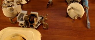
Socket device
The principle of construction of sockets with and without grounding is relatively the same. With one small difference, internal or surface-mounted grounded receptacles have built-in metal grounding pins on the sides of the plug socket.
The complete structure of the socket is as follows. Contacts for the plug with springs and terminals are attached to the ceramic or hard-to-flammable plastic base; grounding elements and clamps for fastening to the socket box are also attached to the base (there are no such clamps in surface-mounted devices). And all this is covered with a highly flammable plastic casing. Surface sockets are completely, and internal sockets are only the part that is not in the wall.
Installation of sockets
Before looking for how to wire a 4-socket outlet, it is better to become familiar with the requirements and installation process of a simple single device. The fact is that there is no difference in installing double, triple sockets, or devices with a large number of sockets.
Complete blackout is the first condition for any electrical work. When installing, be sure to pay attention to the color coding of the wires. Phase wires (L) can be:
- white;
- turquoise;
- brown;
- red;
- orange;
- pink;
- gray;
- purple;
- black.
But still, 3 colors are more often used - white, black or brown. Neutral (N) - zero working contact - blue or blue. Grounding (PE), which is often called “zero protection,” has a shell of yellow and green stripes (longitudinal, transverse), sometimes a yellow-green tint, and can also be purely yellow or only green.
The process of installing sockets looks like this:
- First, a hole of the required diameter is drilled in the wall for the socket box, and grooves are made for electrical wiring. These operations are not necessary if the task is simple - replacing a failed socket. In this case, pull the end of the power cable out and remove all accumulated debris using a vacuum cleaner or brush.
- To install the socket box, prepare a cement/gypsum mortar. After applying it, insert the installation box into the hole, pull the cable into it, and fix it flush with the wall. Leave the work until the solution has completely set.
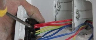
- Then the insulation is removed from the ends of the wires, they are inserted into the contact mounts (phase - on the left, zero - on the right, protective cable - in the center) and tightened with a screwdriver. Check the connection for strength.
- The body is installed inside the box, aligned horizontally, and temporarily fixed on both sides with self-tapping screws. The position is corrected using a level, then the fasteners and spacer tabs are tightened, finally fixing the socket body
- Attach the cover to the body and tighten the central screw. Turn on the electricity and use the indicator to check the functionality of the outlet.
How to visually determine the identity of the wires in a socket
Painting core insulation in specific colors is a way of marking electrical wires. This is done to visually determine the purpose of a particular conductor. This method of determining the purpose is the most visual and convenient for electricians. Manufacturers also apply letter markings. It is also marked in electrical circuits or on devices.
In single-phase current networks
Electrical wiring with a single-phase 220 V network has 2 cores. One is phase, the other is zero. The color coding is usually as follows:
- phase – brown, black, gray, red, turquoise or other color;
- zero – blue.
According to generally accepted markings, the phase conductor can be painted in any color except blue. The zero core is traditionally painted blue or light blue.
A single-phase three-wire network has 3 cores. There is a neutral, phase and grounding conductor. The presence of grounding is one of the main requirements in the installation rules.
The marking of the phase electrical wire is brown, the neutral wire is blue or light blue, the ground wire is yellow-green.
In three-phase current networks (three-wire)
A three-phase 380 V network can be with or without a grounding conductor.
There are three-phase four-wire and five-wire networks. A network with four conductors contains 3 phase conductors and one zero working conductor. There is no grounding.
The neutral conductor is necessarily indicated in blue or cyan; any other color can be used for the phase.
The five-wire network is grounded. It is traditionally indicated by a yellow-green color. The coloring of the remaining wires is similar: zero is blue, phases are of other colors. Typically, phase conductor A is brown, B is black, and C is gray.
Fork adaptation
Quite often there are electrical appliances whose plugs are not suitable for domestic sockets. In this case, there is only one solution to the problem - connecting the device through a special adapter - an adapter.
Adaptation of three-pole design type IEC 60906-1
The distance between the pins for this configuration is 19 mm, the diameter of each pin is 4 mm, like the C5 type. But unlike the latter, they are equipped with an additional grounding pin, which will not allow you to insert the plug into the socket.
To solve the problem, the structure is clamped in a vice and carefully, so as not to damage the necessary pins, the third one is cut off with a hacksaw. The absence of a grounding pin allows you to easily connect the device to an outlet
Adaptation of the English model BS 13-63
Such Euro plugs also have three pins, but are flat in shape. Two of them are on the same horizontal line, they are designed to supply power voltage, and the third is for proper connection and grounding.
The width of each pin is 6.5 mm. The interval between the internal planes is 16 mm, as with type C5. To make the mechanism usable, you will need to reduce the width of the pins by 2.5 mm and remove the ground. The excess is removed with a hacksaw, and with its help the remaining pins are ground off. This is where the adaptation ends, the plug can be used at home.
Read further:
How to assemble a grounding plug
How to replace a plug on a wire
How to change a plug on a wire
How to assemble a socket plug
How to fix a socket plug
Connection features
Electrical plugs with grounding must be connected strictly taking into account the parameters of the device being connected and the current capabilities of the plug part. A Euro grounding plug is the safest option; it is not advisable to use others. Be sure to first find out the power of the connected device (and calculate the current that will flow through the plug contacts). For example, a simple plug cannot be connected to an induction hob, since the hob consumes around 7 kW, and not every plug can withstand these loads. The current can be calculated using the formula below.
For an oven and electric boiler, calculations are carried out in a similar way.
Types of electrical plugs
Currently, in Russia, all electrical appliances are produced with cords at the end with two types of permanent plugs, type C, in accordance with GOST 7396.1-89. The body of each plug is usually marked with a marking indicating its technical characteristics - the maximum permissible current and the permissible supply voltage. This does not mean that the given one is of such strength, but only indicates that the plug is designed to transmit current up to the specified value.
C5
(analogue of European electrical plugs CEE 7/16) - with round pins with a diameter of 4 mm, converging slightly towards the free ends, the pins are insulated to a length of 10 mm from the body, without a grounding contact. The C5 plug is designed for a load current of up to 6 A (with a supply voltage of 220 V it can withstand a power of 1300 W).
C6
(analogous to European plugs CEE 7/17) - with round pins with a diameter of 4.8 mm, there are three-pole with a grounding contact and two-pole without a grounding contact. The C6 plug is designed for a load current of up to 10 A (with a supply voltage of 220 V it can withstand a power of 2200 W).
There are still many devices in use with cords equipped with collapsible plugs type C1-b
with round pins with a diameter of 4 mm without a grounding contact and designed for a load current of up to 6 A (with a supply voltage of 220 V it can withstand a power of 1300 W).
Instructions for connecting the oven plug
An oven, with or without a hob, is a high-power device that consumes a large amount of electrical current. And if the wiring in the apartment turns out to be unsatisfactory for some reason, difficulties may arise with connecting the unit.
Old and new wiring
The type of oven plug you need depends on several factors. They also influence the choice of outlet. However, with any option, the main safety requirement is grounding. And if the Euro-socket by default includes grounding, then this cannot be said about old wiring and ordinary sockets.
- The old wiring with circuit breakers - on the distribution panel, in the electrical panel and so on, suggests only one solution: to service the equipment you will need to install new three-wire wiring - “phase”, “ground”, “zero”, otherwise there is a risk of the switch constantly tripping, which leads to equipment failure.
- How to connect a plug in an apartment with new wiring is not a question. Equipping with Euro sockets and Euro plugs solves this problem without any difficulty. Most models from Samsung, Bosch or Electrolux are equipped with adapters by default. It is enough to plug the plug into an outlet without a filter or extension cord for the device to work.
There are no such difficulties with gas devices, but they do have their drawbacks.
Another factor that determines which plug is needed for the oven is the power of the device.
- With a maximum, non-working, oven power of 3–3.5 kW, a socket and plug rated for a current of 15 A is sufficient. In this case, when laying the cable, it is necessary to use a copper wire of at least 2.5 square meters. mm in cross section.
- If the power is higher - up to 5 kW, for example, a device from Bosch or Samsung with pyrolytic cleaning, then you will need a 32 A socket, and the copper cable for it must have a cross-section of at least 4 square meters. mm.
How to connect the oven
Quite often, devices - both Electrolux and Samsung - do not come with a plug, but only a power cable. What kind of socket and plug it needs determines the power of the device, and how to connect it depends on the wiring in the kitchen. The photo shows the cable connection.
- First of all, it is necessary to establish that the network parameters in the apartment meet the requirements of the device. The instructions contain a table of factory values, which indicates all the requirements, including which plug is needed.
- A load-bearing plug is attached to the power cable. Connecting the plug to a Samsung, Bosch or Electrolux oven is done in the same way. As a rule, wires are marked in different colors. If the wires are the same, the phase is set using an indicator screwdriver.
- The oven is mounted in a niche in such a way that there is a gap of 30 mm between the back wall and the wall, and 85 mm between the floor and the body. You need to make sure that there are no gas pipes between the device and the wall. The device heats up noticeably during cooking, and gas pipes, due to operating conditions, exclude thermal insulation.
Difference between zero and ground
Some novice electricians do not know what color the ground wire is or what it is needed for. Let's look at this question in more detail. Electric current flows through zero and phase, so you cannot touch them. The ground serves to remove voltage if it breaks through to the body of the device. This is a kind of protection that has become mandatory in recent years - some devices do not work if they are not grounded.
If you are not sure which wire is ground and which is zero, then use the following tips. They will help you decide without the color code of the wires
- Measure the resistance of the wire - it will be less than 4 ohms (check that there is no voltage on it so as not to burn the multimeter).
- Find the phase, use a voltmeter to measure the voltage between the supposed zero and ground. On the ground the value will be higher than at zero.
- If you measure the voltage between the ground and a grounded device (for example, a battery in a multi-story building) with a multimeter, the voltmeter will not detect the voltage. If you measure the voltage between zero and ground, a certain value will be displayed.
All this is true only for three or more conductor cables. If there are only two wires in the cable, then by default one will be ground (blue), the second phase (black or brown).
Observe cable connections
Colors of wires in a three-core cable
To correctly connect the wires, they are color-coded, which allows you to quickly identify the desired conductor in the bundle. But not everyone knows how phase and zero are designated in electrics, so colors are often confused, which complicates future electrical wiring repairs. In this article we will look at the principles of color marking of wires and tell you how to correctly separate phase, ground and neutral.
Why do you need color coding?
Standard wire colors
Marking allows you to correctly connect wires, quickly find the necessary contacts and safely work with cables of all types and shapes. The marking, according to the PUE, is standard, so knowing the principles of connection, you will be able to work in any country in the world.
Note that the old cables produced under the USSR had one conductor color (usually black, blue or white). To detect the required contact, they had to be ringed or a phase applied alternately to each wire, which led to unreasonable waste of time and frequent mistakes (many remember newly built Khrushchev houses, in which when you pressed the bell at the front door, the light in the bathroom turned on, and when you pressed the switch in the bedroom there was a loss of power in the socket in the hallway).
Different colors of wires in electrics greatly simplified the process of creating wiring, and after a few years they became a standard in Russia, the EU, the USA and other countries of the world.
Ground, zero and phase
There are three types of wires: ground, neutral and phase. The coloring is applied to the entire wire, so even if you cut the cable in the middle, you can still figure out which contact is which. Grounding is indicated as follows:
- Yellow-green color (in the vast majority of cases).
- Green or yellow.
In an electrical wiring diagram, grounding is designated by the abbreviation PE.
Please note: in drawings and in electrician slang, grounding is often called zero protection. Do not confuse it with zero, otherwise a short circuit will occur.
The zero in the cable is indicated by blue-white or simply blue, symbolized in the diagram by the letter N. Sometimes it is called the neutral or neutral contact, so be careful and do not confuse these concepts.
In schematic images, the phase is represented by the letter L. It can be detected with a test screwdriver or a multimeter. When connecting wires, use special clamps or solder them offset relative to each other to prevent short circuit or oxidation of contacts with subsequent loss of voltage.
Classic colors of wires in the cable
Difference between zero and ground
If you are not sure which wire is ground and which is zero, then use the following tips. They will help you decide without the color code of the wires:
All this is true only for three or more conductor cables. If there are only two wires in the cable, then by default one will be ground (blue), the second phase (black or brown).
Observe cable connections
We are looking for a phase
You can find the phase using the indicator
Conclusion
Features of replacing different types of electrical plugs
Replacement of European design
Stages of replacing a European-style electrical plug
As a rule, the need for replacement arises when the integrity of one of the pins has been damaged. The technology is quite simple:
- Replacement begins with dismantling the old Euro plug and removing the outer sheath from the wire. At least 5 cm is removed from the end.
- Each wire core is stripped approximately 15 mm. This length will be sufficient to connect wires in a European-style design.
- All bare wires are cut so that the length of the bare wires is no more than 10 mm. This is enough to replace the plug with a new one yourself.
- To ensure reliable contact, you need to bend the ends of the wires using pliers.
- The next step is the correct connection of the wires. Most cords have three wires. Brown – phase, yellow or green – ground, blue – zero.
- To prevent the plug from wobbling, it must be firmly fixed by clamping the wire with a plastic jumper.
- The final stage is to assemble the working mechanism and check its functionality.
Replacing an old Soviet-style electrical plug
One of the most common plug designs in the USSR, designed for 220V
The old electrical plug has an even simpler design compared to its previous counterpart. The replacement algorithm in this case is slightly different. The main steps that make up the replacement:
The old building is dismantled and disassembled. As in the previous case, the wires are exposed. The ends are trimmed to 15 mm. In this case, there is no grounding, so you only need to connect two wires
When connecting, it is important to pay attention to the polarity.
The final stage is the assembly of a ready-made electric plug.
Wire color coding
Significantly facilitates installation work. The colors of the wires are regulated by the Russian Electrical Installation Rules (PEU) and European standards.
- Grounding is a yellow-green color, sometimes pure yellow or green. Designation on the diagram - PE
- Neutral or zero - blue or light blue. Designation - N
- Phase - brown, black, white, gray, red, purple, orange, pink, turquoise
PEN wire is an outdated grounding system in which the neutral and ground are combined. This simplifies electrical work, but increases the risk of electric shock. Yellow-green color (like PE) or blue like N.
| Surface power, kW | Up to 3.5 | 3,5–5,5 | 5,5–7,2 | 7,2–8,8 |
| Single-phase network, mm2, 3 wires. cable | 3*2,5 | 3*4 | 3*6 | 3*10 |
| Rated current of the difavtomat, A (mA) | 16 (30) | 25 (30) | 32 (30) | 40 (30) |
| Two-phase network, mm2, 4 cores. cable | 4*2,5 | 4*4 | 4*6 | 4*10 |
| Rated current of the difavtomat, A (mA) | 16 (30) | 25 (30) | 32 (30) | 40 (30) |
| Three-phase network, mm2, 5 wires. cable | 5*2,5 | 5*2,5 | 5*2,5 | 5*2,5 |
| Rated current of the difavtomat, A (mA) | 16 (30) | 25 (30) | 25 (30) | 25 (30) |
Expert opinion
It-Technology, Electrical power and electronics specialist
Ask questions to the “Specialist for modernization of energy generation systems”
Connecting the oven to the mains - 3 conditions. Selecting a wire, machine, socket and plug. The retainer for the insides of the plug does not have to be completely removed; you can slightly loosen one of the screws, unscrew the second and, moving the plate to the side, avoiding its displacement while laying the wire, carry out the procedure. Ask, I'm in touch!
Replacing the old Euro plug
You may need to replace the electrical plug if one of the pins is broken. The electric plug has a simple replacement technology, which includes:
It is necessary to cut off the old Euro plug and remove the outer sheath from the cord. From the end you need to cut about 5 cm from the cord.
You need to strip all the wires to 15 cm. This length will be enough to connect the wires to the electrical plug.
Now you need to cut all the wires so that only 10 cm of bare wires remain. This will be quite enough to change the plug yourself.
To improve contact, you need to bend the ends of the wires with pliers.
Replacing a broken Euro plug has the most important step, which includes connecting the wires. As a rule, all cords have three wires. The blue contact is zero, the yellow contact is ground and the brown contact is phase. In order to correctly change the plug yourself, you will need to connect the ground to the central contact.
As you can see, the design of the electrical plug is quite simple. If your refrigerator does not turn off, then you should read about this problem. That is why you can easily carry out the replacement yourself. You can watch this process in the video below.
What does the US plug look like?
For USA there are two connected plug
types, types A and B.
Taper valve
enter
is a plug
that has two flat parallel pins and
a plug
Type B
is a plug
that has two flat parallel pins and a ground pin. USA operates at a supply voltage of 120 V and a frequency of 60 Hz.
- Unscrew the connector cover and remove it from the metal insides.
- Place the cover on the device wire to save your work later.
- Connect the phase and neutral (brown and blue wires) to the two contacts.
- Attach the ground wire to the remaining connector (green and yellow) - if you have one, of course.
Lawn mower fork repair
I was faced with the repair of a non-standard plug, the pins of which were pressed into the body of the switching unit of an electric lawn mower.
Due to the design peculiarities, it was not possible to replace the plug and we had to come up with a technology for fixing the pins.
Not only were the plug pins heavily oxidized from poor contact with the socket on the cord, but one of them was sunk into the plastic housing.
To secure the pins, it was necessary to disassemble the block, but I was faced with the fact that the self-tapping screws had slots with three oblique edges, allowing only the screw to be tightened. I had to heat the heads of the screws with a soldering iron and unscrew them with a flat-blade screwdriver of a suitable tire. After the repair, I screwed in other screws with heads under a standard cross.
The ends of the pins connected to the wires were located under the limit switch, which was fixed in the grooves of the block body.
After removing the switch, the recessed pin was heated with a soldering iron and returned to its original state. But the reliability of its fastening was low. When pressed with fingers, the pin swayed.
To prevent repeated breakage of the plug, the pins on the wire connection side were filled with epoxy resin, as shown in the photograph.
After the resin had cured, the block was assembled and the pins were sanded using fine sandpaper. The test showed reliable operation of the unit. Now the pins of the plug, even in the case of strong heating, will not be able to move.
Second option. Installing a socket with replacing the socket box
We connect the wires and install the mechanism in the socket box. Its fixation is carried out in two ways. The first is with the help of a frame, it is put on the fastening screws of the socket box, fixed horizontally and the screws are tightened. The second with spacer screws, for greater reliability.
In practice, one fastening is enough, using a frame.
Now, attach the frame and insert the protective cover. Tighten the fastening screw.
The socket is connected.
Connection and installation of other electrical wiring elements (switches, including backlit ones, chandeliers and lamps) are described in detail here.
What we need to connect:
How much we saved by installing the switch ourselves:
- calling a specialist - 200 rubles
- installation of an indoor socket box (brick wall, drilling, installation) - 200 rubles
- dismantling the socket box - 100 rubles
- installation of an indoor socket - 200 rubles
*The cost of electrical installation services is shown in the pricing table
Installation process
Preparing tools for installing sockets
Installation of sockets is a procedure that is carried out in a certain sequence.
First you need to prepare the following tools and materials:
- perforator;
- Bulgarian;
- level;
- roulette;
- indicator;
- knife;
- pliers;
- screwdriver;
- pencil;
- putty knife;
- cement;
- sand;
- primer for concrete.
When installing the electrical system, you must wear safety glasses, gloves, and a respirator.
Preparatory work
Wiring layout rules
The scope of this process depends on whether a new cable will be laid or everything will be limited to replacing the socket.
The sequence of actions when electrifying a building under construction or its major renovation is carried out:
- Drawing up a diagram and marking. It should be calculated so that the holes for the mounting boxes are on the same vertical or horizontal line.
- Wall chipping. Grooves are made for the cable and round holes for the points. After drilling, they are connected to each other to install jumpers. The openings are cleaned of dust and crumbs and treated with a primer. If the external method is chosen, channels or fasteners are installed - plastic boxes, metal or plastic pipes, ceramic insulators, strings.
- Installation of socket boxes. The plugs are broken off from them, after which the products are coated with a solution and inserted into the holes. Excess putty is removed.
When the solution has completely hardened, it is sanded flush with the wall surface.
Connecting wires to the outlet
To prevent damage to the cable when the building shrinks or comes into contact with moisture, it should be pulled through a corrugated plastic tube. After this, the channel is walled up in grooves. The ends of the cable are led out into mounting boxes so that there is enough material left to make the connection. Further actions are carried out after the solution has completely hardened.
Connecting the socket
Connecting a double socket with grounding
Before connecting the wires to the outlet, you need to make sure that they are not live. To completely protect yourself, you should turn off the input switch.
After this you need to do the following:
- Remove the insulation from the cable, and then from the cores, exposing 10-12 mm of metal.
- If the wire is copper, twist it and solder it. This will prevent it from oxidizing.
- Connect the ends of the wires to the holes on the terminals. Tighten the bolts as tightly as possible.
- Insert the socket housing into the installation box. After alignment, secure it with presser feet.
- Install the cover. Check the strength of the fastening using the plug - insert it and pull it out of the connectors several times.
After this, you can supply electricity and use the point.
Tools
To connect a Euro grounding plug, take:
- side cutters;
- a screwdriver (depending on the type of screws, Phillips or slotted);
- electrician's knife.
Auxiliary accessories are usually not required. Procedure: standard diagram Let's look at how to connect a 220 V plug with grounding in stages:
- Take a cable - for example, round 3 * 1.5 mm.
- Unscrew the body - from the side or from below.
- Strip the wires of insulation - you need to get three wires with stripped wires at the ends (1 cm is enough).
- Disassemble, unscrew the contact group, connect neutral and phase to the pin contacts (grounding is the contact on the side).
- Connect blue and brown wires to the contacts, yellow to the ground contact.
- Stretch the contacts so that the wires fit tightly.
- Place the parts, assemble the body, tighten the fastening screw.
Check the build quality. How to connect a wire to a grounding plug, see video below:
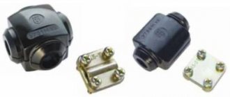
Design features
The design of electrical plugs is divided into several types. You need to familiarize yourself with the technical characteristics, advantages and disadvantages of each in more detail.
Non-removable fork device
The design features of non-separable modifications are the same everywhere. The pins are installed at intervals of 19 mm into a strip made of plastic; conductors are pressed into it. The bar is equipped with two protrusions, the purpose of which is to guide the wire. The bypass is important because it eliminates the possibility of the plug cord breaking if significant force has been applied to it.
The wire and pins are filled with molten plastic. This is ensured by a high degree of tightness of the case with the power cord securely fixed in it.
Device of a collapsible three-pole design
Not so long ago, only collapsible structures were used to connect electrical appliances. Today they are still used by a large number of Russians. You cannot do without such a part if you need to replace a cast mechanism that has failed. The advantage of such a fork is its maintainability and the ability to use it repeatedly. It can be dismantled and installed on another cord without much effort.
Design device type C1-B
This design is incredibly simple in its implementation. It consists of two halves of a plastic body, two brass pins, fasteners and a clamping bar.
Design features of the collapsible structure type C6
The design is also not particularly complicated. Modifications are available with or without a grounding contact. Designed to operate devices with a power of no more than 220 W. The pins are made of brass; contact pads with threads are pressed onto them for screwing wires. The pins are attached to the base of the plug. An additional grounding contact can be installed in the housing, which has the shape of a brass strip. There is also a strip for securely fastening the wire with a plastic gasket.
How to connect a triple socket: into one socket, with one wire
A set of three sockets in one housing allows you to connect a large number of devices to a single power source. The three-module device also reduces the number of wires used. A triple socket is in demand in the kitchen, bedroom or office.
Content
The need to install triple sockets
The use of a three-module socket allows you to use household appliances and electrical appliances comfortably. The joint mechanism has a number of advantages:
- low cost compared to single-module products;
- durable and safe fastening;
- no costs for organizing additional wiring;
- speed of repair in case of breakdowns;
- quick and easy installation.
When installing triple devices, you will need to drill a socket box for three modules. This technique will significantly save space in the apartment and increase the functionality of electrical wiring.
Types of products
According to shape, size and installation method, there are the following sockets with three sockets:
- internal - suitable if the apartment has a hidden type of wiring;
- external – a built-in cover prevents dust from entering the openings, the housing has increased protection;
- built-in and overhead - recessed into the wall surface.
Modern manufacturers produce models with or without grounding, as well as with a fuse that ensures shutdown in the event of a short circuit.
Triple sockets have two types of contacts:
- during operation, petal ones lose their properties of rigidity and elasticity and can spark;
- spring ones are characterized by increased wear resistance.
The optimal contact material is brass.
Features of a socket with a switch
Devices for three consumers with a shutdown button are convenient because the switch de-energizes part of the electrical circuit. This eliminates short circuits or the accumulation of static electricity. The special feature of the device is a one-piece body with three sockets and a power button.
The combined designs differ:
- versatility - can be installed on concrete, stone, wood and plasterboard walls;
- economical - a minimum of installation trenches and holes is required;
- ease of connection - a common wire is pulled, rather than a separate cable for each point;
- speed of surface marking due to the same sizes of products;
- the ability to simultaneously control light sources and turn on electrical appliances.
If one element fails, the entire unit must be replaced.
Triple socket design
The products are made on the basis of a housing and a working part - terminals with springs for the plug and contacts, a grounding device. Modern European sockets can withstand currents of up to 16 A, standard ones - up to 6 A. Sockets in one housing are distinguished by a large diameter of round holes for plug rods. The device cover is made of heat-resistant plastic, the core is made of ceramic. For installation, a special horizontal and vertical panel is used.
The modules are located on a common frame or on 3 autonomous ones connected by a common panel. Today, two modifications of the triple socket block are used:
- C5. Design without grounding in a square housing. It is placed under old Soviet devices and connected to a 220 V network.
- C6. Euro socket that can withstand voltage of 230-380 V. Compatible with equipment with Euro connectors and plugs.
The blocks are suitable for arranging two types of wiring.
The internal one for a hidden highway is mounted using a cylindrical socket box in the walls. The external one is suitable for an open power line, installed on a plate socket box on the surface. Depending on the manufacturer, the triple module has a width from 212 to 220 mm and a height from 72 to 80 mm. The size of the device together with the overhead frame is 160 mm in height.
Connecting electrical points
The structure should be connected taking into account the wire cross-section. When installed externally, the ability of the wiring to withstand 3 consumers is checked. The presence of separate socket boxes provides for the laying of additional cables vertically or horizontally. After these works:
- Separate socket boxes are connected to the cable terminals and pressed using clamps.
- The ends of the conductors are twisted into the device.
- The central part is installed and the overhead cover is fixed.
When installing an outlet to an existing group, the machine is replaced.
Assembly components
A socket suitable for three sockets does not always meet the needs of the buyer or is expensive. The way out of the situation would be to independently assemble a block from single-module products.
You can make a three-module unit from the internal parts of standard sockets with a rated current of 16 A. The overhead frames are removed, the remaining elements are placed in a special cover with three niches. It turns out to be a solid block.
Installation of a socket box
Installation of the block begins after choosing the location of the structure:
- in the kitchen, for one-time connection of equipment, it is better to place the device above the countertop;
- in the bedroom, a three-module product can be installed behind the TV - the wires behind the screen will be invisible;
- When installed in a bathroom, a sealed moisture-resistant block is required, located 60 cm from the water.
After choosing the installation area, you will need to prepare tools - a level, tape measure, marker or pencil, a hammer drill with a crown attachment and an attachment for making grooves.
Carry out installation work before the room is finished.
Marking the wall surface
The geometry of the structure and the convenience of organizing wiring depend on the correctness of the markings. To mark installation points, start from the number of sockets in the block. When working, use a level - it will ensure that the device is level.
The distance of the socket from the floor is 20-40 cm. Between the centers of the socket boxes is 72 mm. Otherwise, it will not be possible to fit the decorative panel accurately. The groove is done strictly horizontally or vertically - it is better to draw the outline of the hole.
Drilling holes in the wall
You can make seats for the socket by punching with a hammer drill with different attachments. A hammer, chisel and several screwdrivers are used to refine areas.
Drilling is carried out in stages:
- Use a drill or hammer drill with an attachment to make a round hole. The crown should be completely immersed in the wall.
- The groove is led strictly vertically or horizontally.
- The width and depth of the channels are made according to the cross-section of the cable or the dimensions of the corrugated pipe.
- The remaining concrete is removed with a chisel.
- For plasterboard or other soft materials, use a special attachment or a sharp construction knife.
- Three holes are made for the wires on the back of the socket box body.
- 2 holes are drilled between them for auxiliary wires.
The permissible cross-section of the cable for the socket is not less than 2.5 mm2.
Fixing a socket box in a concrete wall
To ensure that the triple socket box sits tightly in the socket, white alabaster is used. Due to the rapid setting of the material, the mixture is prepared in small portions. Density is controlled visually.
The landing niche for the socket box is coated with the solution from the inside and its fastening is checked. The product will sit firmly on a dense mixture. If it fails, add more alabaster and reapply the composition. After installation, the solution should dry for 2-3 hours. The outer layer of the material is leveled with sandpaper.
Before placing the socket on the alabaster, check the horizontal and vertical position of the mounting screws.
Connecting triple sockets
The triple built-in socket and overhead device are connected according to the parallel principle:
- A diagram is drawn on which the neutral, phase and ground cables are marked in different colors.
- Use an indicator screwdriver to find the phase and neutral.
- Turn off the power from the panel.
- Jumpers are made from one socket mechanism to another.
- The protection cable is thrown onto the grounding contacts (yellow-green).
- Zero (blue wire) and phase (red/brown wire) are connected to the power contacts.
- The connections are secured with screws.
- The wires are twisted inside the box.
- Level the device by tapping the body.
After tightening the fixing screws, decorative overlays are installed.
Features of connection with and without grounding
A triple socket in one socket box with grounding is connected as follows:
- De-energize the room and check the current flow with an indicator screwdriver.
- Removing the old socket. The central screw is unscrewed, the clamps are loosened, the product is carefully removed from the socket box, and the wires are disconnected or cut.
- Garbage will be removed from the niche.
- The top insulation is removed from the cable in a layer of 20-40 mm from the end and stripped of 3-5 mm.
- The exposed ends of the phases must be connected to the terminals and pressed with screws.
- The yellow-green cable is connected to ground and clamped with screws.
- The socket is put in place and fixed.
The last step is to install the housing cover.
In old houses, two-wire TN-C wiring with a phase and neutral ground (PEN conductor) is installed. Connect sockets without grounding only after checking the voltage with a multimeter. Electric current is not supplied to the apartment at this moment. For installation, it is better to choose models equipped with a grounding mechanism. Complete safety will be ensured only by replacing the wiring.
Safety instructions
When deciding to connect a built-in module, follow the safety requirements:
- Turn off the electricity and break the circuit.
- Use devices and tools with rubber or plastic insulation on the handles.
- Connect the wires with solder.
- Check the cable insulation and, if necessary, place it in a plastic tube.
- Cut the long strand or twist it into a ring and hide it in the wall.
- Extend a short wire, hiding the contacts.
- To prevent a short circuit, check that the socket and wire match the power and current in the circuit.
- Install the triple module in a wooden house only in a metal socket box.
- Place the module near the door so that the switch is closer to the opening than the socket.
Compliance with safety precautions will help to carry out installation work efficiently.
The built-in socket block is convenient to use. If you have the skills and knowledge, you can connect the switching device yourself. The main thing is to follow the sequence of work.
How to check for ground in an outlet
We figured out how to connect an outlet with grounding, but it is also advisable to understand whether the grounding works or not. To make everything official, you need to invite electricians. They will use an ohmmeter to measure grounding parameters. In general, this procedure is mandatory before putting electrical wiring into operation - today no one will connect your electricity without grounding. Moreover, grounding must meet the requirements, but no one checks it on sockets. You just need to invite electricians.
In different countries, sockets and grounding contacts have different shapes. In our country there is type F
Self check
You can check the quality of grounding in the outlet yourself. But keep in mind: all such methods are prohibited by regulatory documents. There are simply no “normal” and safe ones. There are risky ones in which you can get electrocuted. They usually check it using a tester - this is a socket with a 220 V incandescent lamp of low power (25-30 W). Two wires with a cross section of 2.5 mm² are screwed/soldered to the cartridge terminals. For convenience, you can solder crocodiles to the ends of the wires. And it’s better if they have an insulated housing - it will be easier to comply with safety precautions.
Checks using a light bulb are prohibited.
First, we determine the phase on the outlet. Even if you just connected it, double-check. This can be done using an indicator screwdriver: if the LED lights up when you touch the screwdriver probe, this is a phase. Next, we connect one of the control wires to the found phase. We touch zero with the second wire - the light should light up. When you touch the ground wire, the RCD should trip, since by your test you created a leakage current. If this happens, your grounding and RCD are working normally.
If the wiring is old and there is no RCD, the lamp will simply burn. By the brightness of its glow, you can determine whether the grounding parameters are normal or not. In theory, the brightness of the combustion when connected through zero and ground should not differ. This is if the “ground” works normally. If the brightness drops noticeably with ground, the grounding parameters are bad and it is necessary to redo it, check contacts, pins, etc.
On the issue of safety
Please note once again: it is better to invite an electrician to check the functionality of grounding in sockets. He will take measurements and give a conclusion based on the results
But if you still decide to try one of the methods of self-checking, you need to be well prepared and take all possible precautions:
Avoid touching exposed wires and metal parts with your hands.
- Place a rubber mat under your feet.
- Handle only isolated parts.
- Don't check alone. So that “if something happens” there is someone to react.
But as we have already said several times above, it is better to call an electrician. You may be able to connect a grounded outlet yourself, but it’s better to entrust the quality of the work to a professional.
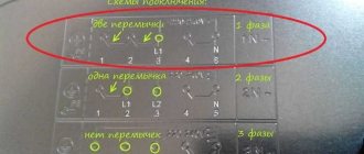
Single-phase network 220 V
The most common option. Three wires come from the control panel and go into the hob terminal block with three, four, five and six terminals. We figured out six terminals - picture above.
For a four-terminal box requiring two phases, the same principle: place a jumper between the phase terminals:
We connect the wires from the house power supply accordingly: L1 - to phase, N to zero, PE - grounding.
Five terminal box . We place a jumper between the phase and neutral terminals:
Just as in the previous example, we connect L1 to phase, N to zero, PE to ground.
Three terminal box. The simplest option, because there are no options. Phase with phase, PE with PE, zero with zero.
To connect an oven with a maximum power of no more than 3.5 kW, you must have the following materials available:
What kind of lighting do you prefer?
Built-in Chandelier
The electric oven must always be connected through its own separate machine. It can be located either in the switchboard or in close proximity to an electrical appliance (more on this below).
If your apartment is being renovated, then start work by chipping the walls and laying the VVGnG-Ls 3*2.5 cable from the electrical panel to the future outlet. If the repair has already been made, then the cable can be laid in a plastic channel or decorative baseboard without damaging the wallpaper.
Many people have a question: is it possible to connect an electric oven from an existing regular outlet that was previously installed in the kitchen for a kettle, microwave, etc.?
It is possible, the main thing is that 3 conditions are met:
According to the third condition, some may experience inconvenience and minor problems. As a rule, many people still have one 16A-25A circuit breaker for the entire socket group, plus another one for lighting.
If you replace the only circuit breaker for sockets with a differential 16A one and connect the oven through it, it will be practically impossible to use other electrical appliances while the oven is working and food is being prepared.
Here you will have to make your own choice, either in favor of saving (not installing new wiring, a separate outlet, etc.), or in favor of comfort and convenience. It is not recommended to leave a regular modular machine in the panel without protection against leakage currents when connecting the oven to an old outlet.
The height of installation of a new socket under the oven should be no more than 90cm from the floor. Although it is also often placed at the level of the kitchen legs.
The most important thing here is ease of use. For safety reasons, when wet cleaning and wiping the oven with a wet cloth, it must be disconnected from the power supply.
And crawling under the very bottom of the kitchen every time to pull out the plug is not always convenient. In addition, here you need to take into account possible situations such as water leaks and kitchen flooding. Therefore, the socket should still be raised 5-10cm above the floor.
Expert opinion
It-Technology, Electrical power and electronics specialist
Ask questions to the “Specialist for modernization of energy generation systems”
Features of connecting hobs to the electrical network | Ranges and hobs | Blog | DNS Club If the second point is not observed, it is necessary to install a circuit breaker of a size in the panel that will automatically turn off when overloaded, thereby protecting the power cable from failure. Ask, I'm in touch!
How to change a plug on a wire
Repairing a power plug is not difficult, but it is very important to follow personal safety precautions while performing work.
How to disassemble an electrical plug type C1-B
It is necessary to prepare the ends of the wires for connection. To do this, the cord is cut at intervals of no more than 5 cm from the plug. If the plug overheats due to an unreliable connection, as a rule, the insulation in these places becomes hard and must be replaced. Rings are formed at the ends of the wire. After this, spring groovers and flat washers are installed on the screws. Now this design can be inserted into the screws.
The screw must be screwed into the pin until it stops. The wire is connected to the second pin in a similar way. They are mounted with protrusions in the housing in special recesses. A strip is placed on the wire and pressed to the body using two screws. If the insulation is thin, in order to prevent it from rubbing where it exits the structure, it is recommended to put a polyvinyl chloride or rubber tube over the insulating layer.
Replacing electrical plug type C1-B
Finally, connect the halves of the housing and tighten them with a nut and screw. If the two halves of the wire are prevented from touching tightly, they need to be moved away.
How to connect a three-pole C6 plug to a wire
Preparing the wire for connection is carried out in the same way as in the previous section. The assembly technology is the same.
If the kit does not include grower plugs, they must be installed. The yellow-green wire can only be connected to the ground contact. As a rule, it is located in the middle between the contact pads of the pins.
Features of replacing a faulty C5 or C6 plug by extending the wire
The instructions below will help you cope with the task without much difficulty.
Let's take an old stand for an electric kettle with a wire and a molded C6 plug. The power cord for electric kettles usually does not differ in length; however, if necessary, replacing the plug may be accompanied by lengthening the cord. If there is no such need, then 15 centimeters is enough to connect to the network.
After this, being careful not to damage the insulation of the wires, cut the sheath along the cord to a length of up to 10 cm and take the wires out. Please note that the insulation itself does not need to be cut. So how do you connect a three-core cable to a plug? A standard cable from the inside consists of three cores, designated by different colors: brown - phase, light blue - neutral, yellow-green - grounding conductor.
Next, adjust the length of the conductors so that the places where the cores are twisted are shifted relative to each other by 1-2 centimeters. Please note that wires of the same color are connected to each other. It is necessary.
Then remove the insulation from the conductors of the wires by about 1.5 cm. If one of the wires is three-core, and the second is without a grounding yellow-green wire, then there is no need to clean the free edge, since you will not connect it anywhere - it remains free .
The protected conductors are connected to each other by twisting. For good contact, three turns of entanglement will be enough.
Do European plugs have ground?
An instruction diagram for connecting the surface terminals to a one-, two- and three-phase network is glued to the bottom cover of the product.
Expert opinion
It-Technology, Electrical power and electronics specialist
Ask questions to the “Specialist for modernization of energy generation systems”
Choosing a Power Cable But here's the catch: If you connect Diagram Wires to the wrong terminals on the output, the output will still work, but the polarity will be reversed. Ask, I'm in touch!
Device
Most plugs have a standard design. They consist of a dielectric body and metal pins. Modern models that comply with the European standard provide an additional grounding contact. Such models usually have a non-separable body. Soviet-style forks are usually collapsible. However, they do not have grounding. This sharply narrows the list of devices on which they can be used.
Non-separable forks
Non-separable models are made using injection molding technology. They can often be found on extension cords. During manufacture, an electrical cable is connected to the conductive pins. Then the resulting structure is filled with liquid plastic mass. Sometimes rubber-like flexible compounds are used.
The result is a monolithic structure. It is completely sealed, so it is not afraid of a humid environment. Such a plug cannot be disassembled so that it can be used later.
Removable grounding plugs
Removable plugs with a third grounding prong are available at almost any electrical supply store. They comply with European safety requirements and allow the connection of a ground wire.
These plugs are sold assembled. The approximate price is 100-200 rubles. They are universal. They can be installed on any household appliance. Often these models have a finger ring that allows you to conveniently remove them from sockets.
Collapsible C1-B
With the advent of European standards, C1-B plugs lost their relevance. Their design is familiar to every electrician. Plug C1-B is suitable for low power devices. For example, for a fan or a table lamp.
The C1-B plug consists of a dismountable plastic housing, brass conductive pins and a pair of screws. Sometimes it is supplemented with fasteners for fixing the cable. The body consists of 2 almost identical halves. They are distinguished by the presence of holes for attaching conductive pins. There is a hole in one half, but not in the other. This point is important for ease of plug assembly. The plastic halves of the housing are secured together with a screw.
Collapsible C6
These plugs are analogous to European models CEE 7/17. They are available in both versions with and without a grounding contact. The permissible power for the C6 plug is 2.2 kW, which allows them to be used on washing machines and instantaneous water heaters. The C6 pins have an increased diameter of 4.8mm. This ensures a tighter fit in the socket slats and reliable electrical contact.
Construction and components
To thoroughly understand how to properly install a new outlet at home, you need to study a little about its components. All sockets are sold already assembled. Therefore, when installing it, you will have to unscrew everything yourself.
We invite you to familiarize yourself with a brick stove for a bath with a firebox from a dressing room: installing an external structure with your own hands, how to install it correctly
The main components of the socket are the base, the conductive part, and the decorative front panel. The base is made of ceramic or high-quality plastic. All elements are attached to it - conductive parts and the front cover.
Ceramic bases are considered more reliable, but they require particularly careful installation, because if damaged, you will have to buy a new socket.
The decorative overlay is designed to hide all working elements. It serves as a reliable insulator of the working part from external influences. Some models provide the ability to simply replace this part of the outlet.
The working part of the socket consists of spring contacts and terminals to which electrical wires are connected. One of the important contacts is the grounding one.
The conductive elements are made of brass or bronze. The latter are better, but are extremely rare. Therefore, you should choose options made from tinned brass - they are more reliable than conventional brass, are better soldered and last longer.
Expert opinion
It-Technology, Electrical power and electronics specialist
Ask questions to the “Specialist for modernization of energy generation systems”
How to connect a 380 volt socket: diagrams and features of connecting sockets with 3, 4, 5 contacts from the panel types and characteristics of sockets Multi-section block sockets are large in size, which often leads to their mechanical breakdowns, since the load from several appliance plugs increases. Ask, I'm in touch!
Types of plugs
Forks are divided into two main types - solid and collapsible. Their operating principle is the same; they differ only in their internal structure. The part of the plug that makes direct contact with the socket is called the pins.
Solid forks
They have pins that do not provide normal contact with old-style sockets, since their sockets do not have coil springs. They are mainly made of plastic or rubber. The pins, together with the attached cord cores, are pressed monolithically with hot plastic or rubber. Constant mechanical stress that occurs during operation can lead to loss of connection between the pin and the core.
Most modern household electrical appliances are equipped with non-dismountable plugs made of plastic. As a rule, such forks cannot be repaired. A temporary repair can be made by cutting through the fork body approximately at the location of the damage. The ends of the pin and the core are soldered to each other. After which the body together with the cut is wrapped with electrical tape. A plug repaired in this way cannot be used for a long time; it must be urgently replaced.
Collapsible forks
Based on a collapsible body. This fork can be easily disassembled and can be repaired in any way. After detecting a breakdown, first of all, its compatibility with the outlet is checked. Old plugs stop working because the wires that are secured to the pins with screws have become disconnected or loose. To hold the cord at the base of the plug, there is a metal bracket inside the housing with two screws.
The housing is disassembled by unscrewing the central screw that holds its parts together. After this, you can check the quality of the connection of the cores. To repair the damage, the core of the cord is connected in a loop to a pin, which is then fixed in the cavity of the housing. Using the depressions, the required distance is maintained between both pins, coinciding with the sockets.
It should be remembered that a poorly secured loop on the pin first of all causes the body to heat up, even to the point of melting the plastic. In this case, the housing must be replaced.
Thus, the question of how to repair or replace a power plug is quite simple and does not require any special skills or special knowledge.
Attach the plug to the wire
Connecting a plug to a wire is an operation performed quite often in the household; for example, in the photographs below, a well pump was connected when constructing a well. He didn’t have his own fork, but for the initial test he needed one.
So we have:
- Fork;
- The cable is two-core (when connecting a three-core cable, you will have to connect a ground wire, but there is not much difference);
- Screwdriver;
- Knife.
Set aside the cable length. It is necessary to leave external insulation on the part that will be pressed by the clamp. This will extend the life of the wire due to the fact that it will not bend too much. Using a knife, remove the outer insulation and expose the conductors.
Using the fixing screws on the plug, we securely clamp the cable cores. If the wire and plug provide grounding (yellow-green wire), then it is attached to the middle contact on the plug. Pay attention to the cable clamp in the photo below. It is not necessary to remove it completely, just loosen one screw, unscrew the second and move the plate to the side so that it does not interfere with laying the wire in the niche. This is how most forks are designed.
Use a clamp to secure the cable to the housing. Now he's definitely not going anywhere.
All you have to do is put on the lid and you can use the fork.
Grounding and zeroing: what is the difference
One of the common installation mistakes is when connecting an outlet with grounding is done by using the “0” two-wire network. This method is called “zeroing” in the language of electricians. When implementing it, “0” is used as both a protective and zero working contact.
The desired effect is achieved by installing a jumper from the “neutral” to the “ground”; but this installation method contradicts the requirements of the PUE
But grounding is not an equivalent alternative to grounding. After all, a line cannot protect itself from itself.
So, for example, if “0” disappears as a result of the same cable break on the input panel or rash actions of an unqualified “craftsman,” the circuit is closed at the moment the device is turned on. But at the same time, the same voltage appears on the neutral wire, which is essentially not connected to the ground, as on the phase wire.
As a consequence: an electrical installation that is grounded by grounding and becomes energized transmits it to a person. The most favorable outcome in this situation is if a short circuit occurs, which causes the machine to “knock out.” Otherwise, the price of such zeroing can become deplorable.
It is also worth considering the fact that according to the technology for installing indoor electrical wiring, packets or two-pole circuit breakers are installed at the input, which switch both “phase” and “0”.
According to accepted standards, in a circuit where there is a switching device, it is prohibited to use the neutral conductor as a protective conductor.
Which fork is better - collapsible or cast?
The cast plug is more reliable; its main advantage is the density of the contacts that connect to the pins. The cast model uses spot welding, soldering and crimping. Another advantage of the model is its tightness.
Read also: Program for cutting pipes at an angle
But there are annoying drawbacks: it cannot be disassembled to eliminate the cause of the breakdown. If the cord frays at the base due to prolonged use, then the only solution is to cut off the molded plug to replace it with a collapsible model. It is possible to completely change the cord and plug to a new one, but to do this you will have to disassemble the device.
However, if such a replacement does not frighten you, it is better to purchase a cast product, especially since, due to its increased reliability, such a fork fails much less often than its collapsible counterparts.
Sockets are the usual way to connect a device to the network. Be it electrical, internet or other network. This article will talk about sockets connecting devices to the electrical network, namely, sockets with grounding.
Brief contents of the article:
Old electrical plug and its replacement
The old electrical plug has a simpler design. Here the replacement technique will be slightly different. Here are the main steps you will need to complete:
First, you need to cut off the old electrical plug housing and disassemble it.
As with the Euro plug, you need to expose the wires. The ends should be stripped to 15 cm of the wire. The design of a regular plug may differ, which is why it is necessary to strip the wires, as indicated in the photo below.
There is no grounding here, so you only need to connect two wires
When connecting, be sure to pay attention to the polarity
Now you can begin assembling the electrical plug housing.
As you can see, the old electrical plug has a simple assembly design. You can see how to do this in the video below. If your washing machine is noisy, then you should read about this problem.
Types
There are two types of grounded electrical plug:
- monolithic;
- collapsible.
Regardless of the form, the content will be the same. Non-separable devices outperform collapsible ones in terms of reliability and ease of use. Maximum elasticity will allow you not to worry about moisture getting inside, contacts being closed or oxidizing. A standard fault with such products is a bend at the base of the connector. But repairing such forks is not impossible. Other parameters of right angle grounding plugs:
- pin contacts – 2 or 3;
- shape - from flat to polygon.
When choosing, be sure to consider the safety factor. Almost every modern plug with grounding comes as standard - the usual ones, where a pair of wires are connected, are not used. Pay attention to the contacts - they are copper, steel or galvanized, nickel, tin with galvanization.
Connecting 380V sockets
Having understood the main types and features, you can consider connecting a 380 V outlet. We will do this separately for each type.
Connecting 2P+PE and 3P+PE sockets
Let's start with the simplest connection of a 2P+PE socket. As the name suggests, for this we need two phase wires and one ground wire.
Socket 2P+PE
Based on this, before making the connection, we need to determine the wire data. To do this, we need to decide on the distribution board in which the connection will be made, as well as on the circuit breaker of the appropriate power.
Two-pole machine
- If you will make all the connections yourself, then first of all we run a cable or wire from the distribution board to the outlet. In this case, a three-core cable of the appropriate cross-section will suit us.
- Now we make the connection in the distribution board. First we connect the protective ground wire. To comply with PUE standards and facilitate the connection of the socket, it is advisable to use a yellow-green conductor. We connect it to the PE bus, which should go in the distribution board in addition to any automatic machines.
Connecting PE and N buses in the switchboard
- After this, we connect the phase conductors. They are connected to the terminals of the machine. Before connecting, make sure the machine is turned off.
- Now we connect directly to the outlet. First of all, we again connect the protective ground wire. Above, we have already decided on its labeling.
3P+PE socket connection diagram
The circuit diagram of a 380V socket of the 3P+PE type is almost identical to the connection of a 2P+PE socket. The only difference is the number of phase conductors, of which in this case we have three. In addition, for such a connection we only need a three-pole circuit breaker and a four-wire cable. Otherwise the connection is completely identical.
Three-pole machine
Connecting a 3P+PE+N socket
We will need the largest number of wires to connect a 3P+PE+N socket. But this does not mean at all that this type of connection is much more complicated.
Connection diagram for 3P+PE+N socket
As in the first two cases, it begins with transferring a cable or wire from the outlet to the distribution board. The cable must be five-core.
So:
- First of all, we connect the grounding conductor to the corresponding bus in the distribution board.
- After this we connect the neutral wire. PUE standards require the use of a blue cable core for this. The neutral bus in the distribution board is also usually marked in blue or with a corresponding letter marking.
- We connect the phase wires last. To do this, we place them on the output of a three-pole machine. Before connecting, make sure the machine is turned off.
Connecting a 3P+PE+N socket
- Now we connect directly to the outlet. First of all, by analogy with a 2P+PE socket, we install a protective grounding wire.
- Now we need to connect the neutral wire. It should be placed on the corresponding contact of the socket. It is usually signed "N". If there is no such marking, then it should be connected to the socket contact that is in contact with the neutral contact of the plug. If you connect both, then simply select any coaxial pin on the plug or connect as recommended in our 380V socket diagram.
- After this, we connect the phase conductors to the remaining three power contacts. This completes the connection. But we do not yet recommend rigidly fastening the socket, and now we will explain why.
The fact is that when connecting to any 380V sockets, it is important to observe the phasing. Otherwise, the engine will rotate in the opposite direction, which is unacceptable for almost all pumps except piston ones.
Therefore, before firmly attaching the socket, connect the pump and check that it rotates correctly.
Changing motor phasing
If the pump rotates in the wrong direction as in the video, then fixing it is quite simple. To do this, remove the voltage from the socket and swap any two phase wires.
Now the rotation will be correct for this engine. If different motors are connected to the outlet, you may have to change the phasing for each of them.
Connection to a three-phase 380 V network
In this case, an automatic machine and an RCD for a three-phase network are purchased; the wires must be five-core (the cross-section is determined using the same table, only the value must be looked at in the 380 V column). The plug and socket must also have five contacts.
The connection process itself will not differ in anything, only in the number of wires. The difference will be when connecting the wire to the output terminals of the electric stove. Only one jumper will be installed - on pins 5 and 6. All others are connected with separate conductors.
Connection diagram for an electric stove to a three-phase network
It is also necessary to monitor the position of “ground” and “neutral” (or they also say “zero”). The color matching of the conductors on the phases is not critical, but it is more convenient if they also match.
From this article you will learn whether it is difficult or difficult to connect an electric stove yourself, diagrams and connection methods (without an outlet and with an outlet), what are the requirements for electrical wiring, safety measures and much more.
Replacement and temporary repair of a monolithic fork
The main reason for the breakdown of many electrical plugs is due to a violation of the integrity of the connection between the pins and the cable wires. Most modern electrical appliances are equipped with monolithic electrical plugs. It is impossible to talk about serious repairs of these products. There is a way to temporarily maintain the functionality of the product: - Cut the body of the plug at the intended location of the break in the connection of wires and pins.
You can restore contacts like this: a) twisting; b) solder to the pins.
Wrap the fork frame with a special tape.
To avoid electric shock, short circuits and fires, if possible, quickly replace the defective plug with a new one.
Fork repair and replacement
If you notice damage to your plug or the pins are not securely secured, it should be replaced immediately. Because for normal and safe operation of the device there should be no signs of damage, and the exposed wires should be securely hidden in the plug itself. Before replacing the old plug, you must cut it off from the cord. Since the section of the cord near the plug itself is most often subject to various kinds of bends, it should be cut off and discarded.
Repairing any fork begins with unscrewing its body.
It is recommended to trim at a distance of 51 mm from the fork. Next, clamp the plug and remove it from the housing. At the same time, on the other hand, hold the body itself, and not the cord. Otherwise, you risk damaging the plug contacts, or simply breaking the wire.
There are a huge number of different models of forks. There are plugs with contacts that pierce the insulation of the housing, and there are also plugs with clamping or screw contacts. In order to remove excessive mechanical stress on the wires, sometimes they are secured in the housing with a clamp. In addition, there are plugs with a grounding third cord. Unlike the flat phase and zero, it has a round shape.
Insulation-piercing plugs are typically used with cords for low-power electrical appliances such as radios, lamps, clocks, etc. There are many different models of this kind of forks.
Installation of a typical plug with insulation-piercing pins. Installation steps:
- Squeeze the pins and pull them out of the housing.
- Cut the end of the wire and insert it into the plug body.
- Open the pins and insert the wire into the hole on the back of the pin block.
- Squeeze the pins and insert them into the housing. In this case, the needles located at the rear ends will pierce the insulation and provide contact with the wire group under the insulation.
There are also plug models that have screw terminals. Such plugs are mainly used with two-core cords for low and medium power appliances. But there are also plugs for three-wire cords with grounding.
Some of them are equipped with a special clamp in the housing, which securely fixes the wires so that they do not break when the plug is pulled out of the socket by the wire.
When installing a plug with screw contacts, you need to thread the cord through its body and separate its wires by approximately 2.5 cm. The ends of the wires need to be exposed by 12.5 mm. Then tie the wires with a safety knot as shown in the diagram below.
A safety knot is ideal for tying wires in a plug.
This unit makes it impossible to disconnect the wires from the contacts when pulling the plug from the socket. The bare wires of each wire must be twisted into a strand and wrapped clockwise around the screw. Tighten the screws and you're done!
A plastic or fiberglass disc is placed over the pins and thereby covers the ends of the wires that are located in the plug body. In this case, the wires inside are tied into a safety knot.
Plug with screw terminals for low and medium power appliances. Elements:
- screw contact;
- pin;
- safety knot;
- The wire is wound onto the screw only clockwise.
Remove the plastic or fiberglass insert protecting the fork body.
Pass the cord through the body and expose the ends by 12.5 mm, after which the wires need to be tied in a knot. This unit removes the mechanical load from the contacts.
Wrap the previously exposed wire end around the screw clockwise. In this case, the neutral wire must be connected to a wide pin, if one exists. All that remains is to return the plastic insert to its place.
There are plugs with pins of different widths, which can only be connected to an outlet with matching sockets. Due to the fact that this plug has only one connection option to the socket, it will not allow you to connect it incorrectly, making the neutral wire of the device a phase. The phase (black) wire in such a plug is connected to the narrow pin, and the neutral (white) wire is connected to the wide one.
Also today there is a wide variety of coupling sockets. They are installed in exactly the same way as plugs and look like a socket installed at the end of an extension cord.
A typical connection socket at the end of an extension cord. Essential elements:
- extension cord;
- wire clamp;
- upper part of the body;
- brass screw;
- screw contact;
- green screw;
- mounting screws;
- lower part of the body;
- white screw;
- It is advisable to screw the bare end of the wire onto the screw only clockwise.
Installation of switches on a wire
As a rule, low-power switches have contacts that pierce the insulation. Such switches are usually used to control lighting lamps. For more powerful electricity consumers, there are switches with screw contacts. The installation process for both types of switches is practically no different. The main thing is to always follow the instructions that come with the device.
Before starting work on installing the switch, make sure that the cord is de-energized. Cut a small piece of the phase wire and place the wire in the back of the switch housing. Close the front part and secure with the mounting screws.
Don't forget to check the instructions first to make sure all the wires are in the right place. As the screws are tightened, the wire insulation is pierced with special metal needles that come into direct contact with the wire underneath the insulation. It is this circumstance that makes it possible for the mechanism located behind the switch wheel to close and open the circuit.
The main stages of installing a switch on a wire.
First of all, cut off a small piece of the smooth phase wire.
Open the switch and place the wires as written in the instructions. To put the wheel in the on position. and off, it must be rotated counterclockwise. This wheel is directly connected to the mechanism, which ensures the closing and opening of the phase wire contacts.
On the front of the case there is both a wheel and a mechanism for opening and closing contacts. When mounted on the back of the housing and subsequent tightening of the mounting screws, the needles pierce the insulation, due to which the contact of the wheel with the phase wire operates. The mounting screw must be tightened properly to secure both halves of the housing together.
Installation procedure
The angled plug with grounding is installed according to the following diagram:
- A phase is connected to one contact of the plug, which supplies voltage to the consumer.
- The wire with zero is connected to the other contact. Ideally, the zero, neutral contacts should carry a current of the same value. In the event of a short circuit, it increases and the protection is triggered. Connecting the neutral to the housing or ground loop is prohibited.
- The third ground pin is connected to the ground wire. It does not have a direct connection with the phase wires. It is inextricably linked with those parts of the structure that are grounded.
Since there is no uniform standard for the production of electrical plugs with grounding in different countries, there are many types of plugs. Here are some food types in other countries:
- 110-127 V and 60 hertz - USA;
- 220-240 V, 50 hertz - Euro plug with grounding.
In Russia, the euro version is accepted as a single standard, not the American one.