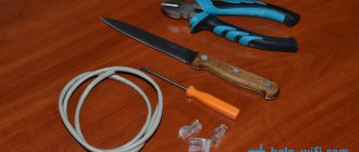
How to crimp a network cable without crimping
The network cable is a capricious thing; sometimes the plug falls off, sometimes it starts to dangle from side to side. When you call your provider and say that you do not have Internet, they send installers, and they, first of all, crimp the network cable and replace the RJ45 connector.
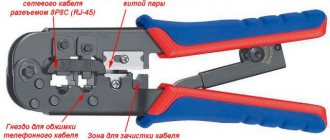
But what to do if the connector falls off at night? Why not sit without the Internet until the morning, waiting for the installers to arrive? That's right, you can take and reconnect the network cable with your own hands, without a special tool. In this case we are talking about the so-called crimping - pliers for twisted pair cables.
Cutting twisted pair cable for crimping
Cutting a twisted pair network cable for crimping is the first and most critical step in crimping.
The reliability of the connection between the conductors of the twisted pair cable and the RJ45 plug, and as a final result, the stability of access to the Internet, depends on the accuracy and correctness of its implementation. The main thing when cutting is to avoid notching the twisted pair conductors and to prevent them from overlapping at the point where they are clamped by the clamp in the RJ-45 plug. Crimping pliers for RJ-11 and RJ-45 plugs, as a rule, have special knives for cutting the twisted pair cable to length and trimming its outer sheath. But I never use these functions of pliers, since I have repeatedly had to deal with the consequences of such pruning.
The fact is that a twisted pair cable is far from an ideal circle, since all the pairs are twisted around each other; when cutting in pliers, the copper strands of the conductors are often cut and a few bends are enough for them to break off. Reliability can only be guaranteed by manually preparing the cable end for crimping.
Cutting a network cable begins with removing the outer sheath. To do this, one jaw of the side cutters is inserted inside the cable. Care must be taken to ensure that no conductors come into contact with the cutting edge. Most cables have a split nylon thread running inside them. After opening a couple of centimeters of the shell, you can grab it and, pulling it away with tension, cut the shell by 4-5 cm. Next, the shell is bent to the side and cut off with side cutters. Many people recommend removing the sheath by 14 mm, but with such a length it is almost impossible to develop and align the twisted pair conductors well.
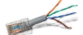
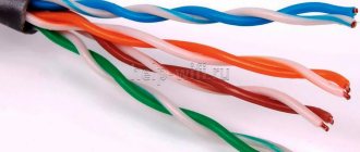
Next, the twisted pairs themselves develop counterclockwise; usually they are twisted clockwise when looking at the end of the cable. They must be developed in such a way that the pairs are in the same plane to a shell depth of up to 5-8 mm. This condition must be observed to prevent the conductors from being squeezed by the plug clamp when crimping with pliers. In this case, it is necessary to immediately orient the pairs by color, taking into account the color markings for crimping.
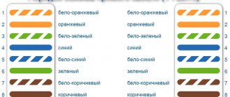
Color scheme for twisted pair crimping according to option B, the most common option.
The twisted pair conductors are developed and straightened until they are in the same plane at the point where the RJ plug clamp is clamped. The twisted pair conductors are shortened to a length of 14 mm and inserted into an RJ-11, RJ-45 plug. It is imperative to check that all conductors are under the contact teeth and their alternation corresponds to the color marking. Sometimes when the wires are inserted into the plug, they change places. The conductors in color scheme B are arranged one after another, white with colored stripes - colored. This allows you to quickly check at a glance that the wires are routed correctly.
Crimping a twisted pair cable without a tool (crimper)
If you have everything you need, you can start making the cable. I will try to show everything as detailed and step by step as possible.
1 Remove the outer insulation from the twisted pair. About two centimeters. Lightly cut the insulation in a circle and pull it together. Just be careful not to damage the insulation of the wires themselves.
2 Straighten the wires and set them by color. According to the scheme that you chose (photo above). It is advisable to arrange them so that they do not intertwine. I got it like this:
3 Next we need to trim the wires. Leave about a centimeter. I will do this using special cable cutters. As I wrote above, you can cut them with scissors or a knife.
4 We check whether the wiring is correctly aligned according to the diagram, and insert them into the connector. We hold the RJ-45 connector itself with a latch away from us. As in the photo below.
Insert the wires until they stop. They should go all the way in and rest against the front wall of the connector.
5 Once again we check whether the twisted pair has entered the connector correctly, and proceed to crimping. We take our screwdriver (maybe you have something different), and press in the contacts one by one. Be careful not to hurt your hand!
The contacts must be pressed in firmly. So that they pierce the cable. The contact itself should not just align with the connector body, but be slightly recessed into the body. The task is not the easiest. When I crimped the cable with a screwdriver, it was difficult to insert into the LAN port of the router (but it was already working), after which I further tightened the contacts with a screwdriver.
After I crimped each pin, I also snapped the cable clamp into place. It is simply pressed inward and the outer insulation is pressed down.
All is ready. We do the same on the other side of the cable. I got it like this:
As you can see, the contacts themselves were slightly damaged by the screwdriver. When crimping with a crimper there is no such damage.
I tested the cable by connecting my laptop to the router. The Internet appeared on the laptop, which means that everything worked out and is working. I managed to make a network cable the first time. Even without a special tool, using a regular knife and screwdriver. I hope everything worked out just as well for you.
How to crimp RJ-11, RJ-45 with pliers (crimper)
Crimping of UTP computer twisted pair cables into an RJ-11, RJ-45 plug is performed with a special crimping tool - plug crimping pliers. Professionals call these pliers Crimper.
. By design, they come in two types: lever and press. Lever pliers (pictured left) are inexpensive and work accordingly. A lot of force is required and the compression is skewed. The best are the HT-500, in the right photo, they are devoid of the noted disadvantages. Their design is such that when twisted pairs are compressed, the comb that recesses the contacts in the plug moves strictly perpendicular to the plug.
To crimp a network cable with pliers, you need to cut and thread the twisted pairs into the plug, insert the RJ-11 or RJ-45 plug into the required cell of the pliers and press their handles together with your hands until they stop.
Press the latch of the RJ-11, RJ-45 plug to its body and remove the twisted pair cable, ready for use, crimped with the RJ-45 plug, from the pliers.
Twisted pair straight and cross crimp circuits, 8P8C connector (RJ-45)
Direct crimp
Used to connect a network card port to network equipment (switch, hub, router).
Crimping according to EIA/TIA-568A standard.
A computer is a switch, a computer is a hub, a computer is a router.
Crimping according to EIA/TIA-568B standard (used more often).
A computer is a switch, a computer is a hub, a computer is a router.
Cross crimp
Used to connect two network cards directly.
Crimped for 100/1000 Mbps, EIA/TIA-568B and EIA/TIA-568A standards apply.
Computer - computer, switch - switch, hub - hub, router - router.
Four wires
Another option for 4 cores is the case when there are only 2 pairs. This is how they usually do it:
The whole point of proper pinout is to match the wires on both sides of the cable, without even knowing how the connector on the other side was crimped. An unspoken standard where you don’t have to run to the provider’s shield. The numbers 1-8 in the pictures are sometimes squeezed out on the sockets, this is for those who do not want to confuse the order.
How to crimp RJ-11, RJ-45 without pliers
Sometimes you urgently need to crimp a cable with an RJ-11 or RJ-45 plug, but you don’t have pliers at hand. In this case, you can do the crimping manually without a specialized tool. Insert the cut conductors of the twisted pairs into the plug, in accordance with the required color scheme, clamp the RJ in a vice by the latch, and using a screwdriver bit with a small hammer, tapping the bit, deepen the lamellas to the desired depth. Snap the cable clamp onto the plug body.
The thickness of the bit blade should not exceed 0.55 mm, since the thickness of the lamella in RJ forks is 0.56 mm. Otherwise, you can flatten the insulating sides. The spring-loaded contacts of the socket will cling to these places and there will be no contact. If the sides are damaged, you need to use a sharp knife to cut off the overhanging edges at the points of damage.
Checking internet cable compression
To check whether the wire has been crimped correctly, you need to use a special cable tester. It is used after the entire operation. If the tool detects problems, the red LEDs will light up. When the connection is correct, the light will turn green.
The tester will help identify the problem
You can check the cable for operability in another way: by connecting it to a router (Beeline, Rostelecom or other manufacturers) and a computer. If the Internet connection appears, then there are no problems with the equipment. Otherwise, you will have to disassemble the connector and carry out the operation again.
How to re-crimp RJ-11, RJ-45
There are, at first glance, more dead-end situations. You urgently need to crimp an RJ-11 or RJ-45 plug onto the network cable, but you don’t have a new plug at hand. There is also a simple solution for this problem. It is necessary to hold the fork body in a vice by the latch and pull the lamellas out of their seats by 1 mm, prying them alternately from the ends with an awl.
Use a knife to cut the latch on the near side to the cable, remove it and remove the old twisted pairs. I completely disassembled the RJ-45 plug to demonstrate its components.
Crimp new twisted pairs into an RJ-11 or RJ-45 plug using the technology described above.
Since the UTP cable retainer was removed when disassembling the plug, it is necessary to fix the cable in the plug by dropping a few drops of silicone, glue or sealant into the resulting window from the removed latch. If there is a need to extend or repair damaged twisted pair cables, this can be done by soldering or twisting. The reliability of a soldered connection exceeds any mechanical methods.
LAN network cable crimping diagram
There are only two ways in which you can crimp a LAN network cable. Usually direct crimping is used.
This method is ideal for connecting a TV, computer or laptop to the router via cable. At home, the wire must be crimped according to the diagram provided below. This method is called direct, and it is the simplest and most common in the absence of special tools.
The network cable for connection must be included with the equipment, so you do not have to buy it additionally. There are two types of crimp available for this option: T568A and T568B.
Connection diagram No. 1
The second method (Scheme 2) is called cross or cross. This cable can be used to connect several computers at home via a wire without a router.
Connection diagram No. 2
Important! If you have no experience working with wires, then it is advisable to call a specialist to your home. When he arrives for a call, the master will take the crimper with him and easily cope with the task.
The concept of a network cable, what does the term compression mean?
Engineering communications, including local computer networks, contain cable connections through which information is transmitted. The type of cable and the quality of its connection contacts determine the transmission speed of data packets, attenuation, losses and the distance over which a full signal is transmitted.
There are three main types of cable for building data exchange networks:
- coaxial;
- with twisted pairs;
- fiber optic.
Coaxial cable was the very first to be used for transmitting information in local computer networks; now this type is almost never used. The reasons for abandoning this technology were:
- complex and expensive design;
- low information transfer speed 10 Mbps;
- short transmission distances without signal amplification up to 500m;
- poor noise immunity and difficulty in repair.
Twisted pair cables are the most commonly used type of cable for organizing networks, this is due to the good quality-to-price ratio and quite satisfactory technical characteristics. At a distance of 50 m, 40 Gbit/s is transmitted; in this example, we will look in more detail at the structure of the characteristic and compression methods.
Twisted pair cable design
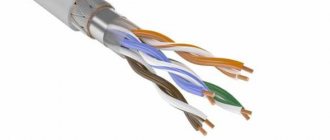
It has four twisted pairs, 8 copper wires, cross-section 0.4-06 mm, polyvinyl chloride coating is used as core insulation. Manufacturers produce some types of higher quality and more expensive ones with polypropylene or polyethylene insulation. The highest quality and most durable insulation has a Teflon coating, 0.2 mm thick.
Protection against interference is provided by a shielding coating with some design differences depending on the modification and purpose of the products. Shielding can be of several types:
- Only individual pairs are shielded with foil;
- general foil shell;
- shielding is carried out with fine wire mesh, individual pairs and the entire cable;
- pairs are shielded by a copper mesh, and the overall shield is provided by a foil shell;
- The overall screen is made of two shells made of foil and woven metal mesh.
These features must be taken into account when cutting ends before installing connectors and crimping.
How to crimp wire lugs without tools
From the point of view of construction technology, crimping wires without the appropriate tool is prohibited, the only exception being rough installation to check the work performed. However, for any household work with low-current consumers, work without a crimping tool is allowed.
There are several methods for ending cords without tools:
- soldering using refractory high-temperature solders;
- “non-standard” crimping using cores, hammers, and notching the tip
Soldering tip
For soldering, you, of course, do not need serious and expensive press pliers/crimpers, but the following “household” repair tools should be present in your arsenal:
- Soldering iron (from 80 W)/blowtorch/gas burner.
- Soldering kit (fluxes/rosin, various types of solders).
- Heat shrink tubing and/or electrical tape.
- Basic knowledge and skills of working with a soldering iron.
The algorithm of actions is as follows:
- if you have a soldering iron/blowtorch, heat it up to operating temperature, if you don’t have one, turn on the burner on the kitchen stove;
- While the tool is heating up, we perform operations to remove the insulation from our cord (remove with a margin of 0.3–0.5 cm), making sure not to damage the cores;
- we put the thermal insulating braid on the cord and move it to a safe distance until we need it;
- degrease the cleaned area;
- degrease the tip;
- apply flux to the inside of the tip;
- Pre-cut the solder into small pieces so that it covers the inside of the tip by about half to a third;
- apply flux with a soldering iron to the stripped part of the cord, tin it (if there is no soldering iron, then skip this step);
- carefully, holding the tip with pliers so that the solder particles do not fall out of it, place it on the kitchen tile (if you don’t have a soldering iron) or heat it with a soldering iron/lamp/burner for several minutes until the solder inside becomes plastic and liquid;
- as soon as the solder is ready, quickly and carefully take the cord by the insulation and install it into the tip, while continuing to heat the tip, holding it with pliers, if there is an empty space between the tip and the solder does not come out, then add solder to these places until it will not begin to “crawl out”;
- then turn off the soldering iron/burner and give it a few minutes for the solder to completely harden;
- After hardening, we wrap 2-3 layers of electrical tape around the connection between the cable and the tip, move the thermal braiding, securing it at the edges with electrical tape.
Crimping using a core/hammer
This method has many disadvantages, the main one being insufficient pressure, which can lead to heating of such a connection. However, it is often practiced, especially in cases where the connection will not work with high-current devices.
This method requires a minimum of tools:
- Hammer.
- Kern (optional, but recommended).
- A small file for metal.
- Vise (optional, but recommended).
- Conductive paste (highly desirable).
- Insulation tape and/or heat shrink.
To finish with these tools, we do this:
- remove the insulation from the cord (margin 0.3–0.5 cm);
- make sure that the wires are not damaged;
- straighten all the wire strands, twist them slightly (half a turn, no more!);
- take the tip and make a small cut with a file (about 1/5 of the entire length of the tip) on the wire side;
- put on the heat shrink, move it 10–20 centimeters so that it does not interfere; degrease the cord;
- evenly apply conductive paste;
- we clamp the tip in a vice or place it so that it can be comfortably held with one hand;
- after which we completely install the wire into the tip;
- we take a core and a hammer and begin to strike the central part of the tip, which should be “compressed” (if there is no core, then you can use the thin part of the hammer);
- make 4–5 fixation points;
- turn the tip over and repeat the operation;
- check the connection for strength;
- We put heat shrink on the connection, heat it;
- ready, the connection is pressed!
How to correctly press wires onto the plug contacts at different ends of the cable: 2 layout options
When connecting a computer to a switch or router, the transmitter on one end is required to match the receiver on the other end. Otherwise, the communication channel will not function. To ensure this, the entire variety of connection options comes down to two main groups: connecting devices of the same or different levels. For definiteness, it is accepted: the computer is located at the lower level of the network, and the switch or router is located at the higher level.
Direct connection
The illustration shows a direct connection, so called because there is no internal crossing of wires. This connection is taken as the main one and is intended to implement the most common connection of devices of different levels to each other. Its distinctive feature is the identical layout of wires along the contacts of the plugs at different ends.
Definition. Wire layout (pinout) along the contacts of a twisted pair connector is a standard-defined scheme for distributing twisted pair wires over individual contacts of RJ45 connector elements, ensuring the correct transmission of signals of various types between the transmitter and receiver.
Crossover circuit
The figure shows a crossover circuit. It is used when connecting two computers or switches, that is, devices of the same level. The crossover circuit restores the correct connection of receivers and transmitters on different sides by internally crossing individual wires. Modern switches have internal switching circuitry and automatically establish the connection order regardless of the type of cable connecting them.
Difference between direct and crossover layout
Look at the figure: it clearly shows the difference between the direct and crossover layout of the wires along the contacts.
Two types of direct connection pinouts
Look at the picture, which shows two types of direct connection pinouts, designated 568A and 568B. For signal transmission, the circuits are identical. The difference in the layouts of individual wires used in them: the blue and green pairs are swapped. Local network and computer wiring standards consider the 568A wiring to be the main one, relegating the 568B to an alternative role. Despite this, the 568V circuit is noticeably more common.
Important!
To eliminate the risk of violation of the connection diagram, it is advisable to use the same wiring of all connector components in the network. All other things being equal, it makes sense to use the 568B circuit.
Crimping the RJ45 connector with a SCREWDRIVER
Main types of crimping pliers for ferrules
The need to use crimping for wires may arise in two situations: in the case of preparing live parts for fastening to the terminals of various electrical appliances and when connecting wires and cables. Depending on the purpose, one or another crimping tool is used. Based on their design features, pliers can be divided into two main types:
- operating on the principle of pliers;
- diaphragm.
The first option is the most common. Pliers are crimped on both sides; they are distinguished from pliers by special recesses on the jaws, which allow the joints to be made as strong as possible.
The convenience of using this type of pliers is that you do not need to choose the position of the tips; you can perform the action from any side. Some problems arise in situations where the sleeve does not fit into the matrix. In this case, you need another pliers.
Crimping the end with diaphragm press jaws is characterized by high density
Diaphragm presses for wire lugs crimp the sleeves on four or six sides, and they themselves adjust to the thickness of the cable. Crimping the end in this way is characterized by high density.
Crimpers are a special type. Although many people call any crimping pliers this way, in this article this concept will be applied to a tool for working with computer and Internet connections. The specifics of this device are discussed further in the article.
Hydraulic crimping pliers for wire lugs
During electrical installation work, hydraulic mechanisms are actively used. The main components of such press jaws are:
- pens;
- axis;
- head;
- matrix.
For hydraulic pliers for crimping wire lugs, the head can be closed or open. With the closed version, the stopper first opens, the matrix is pulled out, the wire with the sleeve is inserted, closed, and only after that the crimping is performed. In a design with an open head, there is no need to carry out preparatory actions, so crimping is much faster.
Each model of hydraulic clamps is designed for a certain size range of wire cross-sections. The maximum value is 400 mm. In everyday life, such conductors are not used, but it is convenient to work with a tip for crimping wires with 6 mm hydraulic pliers. However, there is a danger of pinching.
A manual hydraulic press for crimping cable lugs can have a closed or open head
To more clearly imagine the consequences of squeezing a hydraulic press, it is worth understanding the mechanism of its action.
Due to the swinging of the handle, the plunger (pump piston) produces translational and reciprocal movements, creating a certain pressure, under the influence of which oil enters the cylinder. The oil moves the cylinder, which, in turn, creates pressure in the matrix, and it acts on the liner with the necessary force.
Internet cable crimping tool
The stable operation of any cable system consists of several indicators. First of all, this is the quality of the material of the cable itself. Next comes the professional level of the specialists who carry out the installation. The technical condition of the equipment matters. Completely unreasonably, one of the latter is the quality of connections.
Many models of pliers for crimping Internet cables are equipped with special cutters
It is the contacts that are quite often the cause of unstable or weak signals. Problems associated with unprofessionally made connections in the cable system can only be avoided by using a special tool - crimping pliers, called a “crimper”.
Making any cable connection always begins with stripping the insulation from the ends of the wires. For these purposes, there is also a separate type of tool called a “stripper”. With its help, the top layer is removed, there is no danger of damage to the core. As an option, you can purchase a crimper that has elements that allow you to clean it. This is a hole with a blade on one side. By inserting the wire and twisting it once, you can get the desired result.
Crimpers for crimping lugs and stripping wires are actively used by specialists when installing structured cable systems.
What is an electrical cable made of?
Any electrical cable consists of cores.
The cores are the main elements of the cable and serve to pass electric current. The elements are enclosed in a common shell and isolated from each other internally. They are designated as TPG (current-carrying conductors). In addition to the cores, the cable contains:
- aggregate;
- wire armor or steel;
- outer shell.
There are two types of veins:
- Solid single-wire;
- Stranded from many thin threads.
The main misconception of people is that solid cores and solid cables are the same thing. But this is not true at all. In reality, solid-core cables have only one core, which can be single-wire or stranded.
Solid core of a single-core wire Solid cores of a double-core wire
Wires for installing wiring in an apartment or house are usually chosen based on the convenience of work, experience and skills of the master. In terms of the speed of electric charge transfer and quality, single- and multi-wire wires differ insignificantly
When choosing, pay special attention to the flexibility and strength of the core
Stranded wires in a cable have a higher flexibility index than single-wire wires. They are easier to work on hard-to-reach areas or on routes with a lot of bends. The advantages of multi-wire conductors include the fact that they are difficult to damage.
Single-wire wires are most often used in places where network improvements, connection of additional lines and repairs are not expected. The main disadvantage of single-wire strands is that after a couple of bends they begin to break.
Both wires are connected according to the same technological rules, however, when forming connections, it is still worth taking into account the ability or inability of the wires to bend many times without damage.
One wire that conducts current is connected by twisting only by professional electricians who have extensive experience behind them. Since with such a connection it will no longer be possible to unscrew and redo the knot.
It is best to strip a cable with a current-carrying core made of one wire and connect it to a terminal. This method is used at home. But you can buy a connector that will reliably fix all the components of a stranded core or a tip that is capable of crimping all elements before connecting.
The main material for the manufacture of TPG is aluminum or copper. If we compare these two metals, then aluminum loses in terms of characteristics, even despite its low cost. After all, this metal has low electrical conductivity.
That is, even with the same cross-section, a copper conductor can pass more current. The only drawback of copper is the inability to combine with other metals. If, for example, you need to connect copper with aluminum, you will need a special terminal block to avoid oxidation of dissimilar elements.
Using aluminum for home wiring is not the best solution, because the material has low electrical conductivity, and during operation it quickly oxidizes and breaks at bends.
If the connection is made by twisting, then corrosion will quickly appear at the connection point, the contacts will break, and as a result a short circuit may occur. The best solution would be to select wires of the same type for all power lines in the apartment.
The insulation layer can basically be:
- rubber;
- polyethylene;
- made of polyvinyl chloride.
All of these materials have high insulating properties. Therefore, they can be used in electrical networks with different voltage classes (up to 500 W).
The main purpose of the outer braid is to protect the conductor from moisture, since it can damage the integrity of the insulation and the conductors will begin to become cloudy.
Typically, the cable used for wiring in an apartment or inside a house has two insulating layers.
- The first layer protects the internal cores collected in a bundle;
- The second layer encircles only one core.