- quick identification of wire purpose (phase, neutral or ground)
- reducing the number of erroneous connections during the installation process
- no need to test the wire for phasing
Manufacturers choose conductor colors not according to their own wishes, but according to the rules. Moreover, not only a color, but also a numerical and alphabetic designation can be applied to the conductor.
The color is applied along the entire length of the core insulation. But in some areas you can also use multi-colored cambrics for heat shrink. They are mainly widely used in cable terminations.
Coloring for 220V and 380V single-phase and three-phase voltage
In a three-phase network, wires and buses were previously colored as follows:
Phase A
Yellow color
Phase B
Green color
Phase C
Of red color
To make it easier to remember the order of colors, electricians used the abbreviation ZH-Z-K.
From 01/01/2011, new standards were introduced in accordance with GOST R 50462-2009 ():
Phase A
Brown
Phase B
Black
Phase C
Grey
Now it's time to switch to abbreviations - K-H-S! Subjectively speaking, this marking is inferior in clarity to the previous color scheme Zh-Z-K.
Imagine that there is poor lighting in the control room or room, dust on the wires? Which do you think your eye is better at distinguishing between yellow and green or brown and black? The rules in this case stipulate the need for letter designation and marking of the cores, in addition to color.
Wires and cables
A wire is an electrical product designed to transmit current from a source to a consumer. It consists of one or many copper or aluminum conductors of a certain cross-section.
A cable is several insulated conductors twisted into a round bundle, on top of which a general protective insulation is applied, protecting the conductors from external influences.
Polyvinyl chloride, polyethylene, rubber and others are used as insulating materials.
Letter designation of wires
What should be the letter designation of wires according to GOST is presented in the following tables:
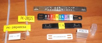
It is best to apply these letters using special tag rings.
They are a PVC tube, pre-cut, with letters and numbers printed on it.
According to the new rules, marking phase conductors yellow or green is prohibited. Precisely because of their similarity with the yellow-green grounding conductor.
It is also worth noting that the brown color is precisely phase A or L1 (simply L in a single-phase 220V network), and black is phase B or L2. When you conduct wiring for yourself, you may unwittingly miss this moment. But if the electrical work is being done for an industrial facility, then you will be required to strictly adhere to the international standard and correct phasing.
White color is the cheapest option when making core insulation, as it does not require the use of dyes. Therefore, it is most often used by manufacturers of cheap cable brands. There are no special labeling guidelines for this color.
Conductors in electrical installations
Consumers of electrical installations can operate from a direct or alternating current network with one, two or three phase voltage.
To power any electrical installation, at least two conductors are required, which, depending on the functional purpose, have an alphanumeric designation according to GOST R 50462-2009:
- Phase conductors L.
- Neutral conductor N.
- Protective conductor PE.
- Protective conductor PEN.
The phase wires connected to the output of the voltage source are designated by the letter L for single-phase circuits, and for a larger number of phases - L1, L2, L3, respectively.
In practical diagrams, there are outdated domestic designations of electrical circuits in letters of the Latin alphabet: A, B, C, N, indicating phases and neutral.
In the USA and some European countries they are labeled as R, S, T, N.
The neutral conductor is connected to the midpoint of the voltage source. For all electrical installations it is designated by the letter N.
Protective earth conductor PE
At one end it is connected to the protective grounding loop or to the neutral bus of the switchgear, and at the other to a metal non-current-carrying protected object. This could be an electric motor housing, a machine frame, a permanent or portable fence, etc.
If an insulation breakdown occurs, a large short circuit current occurs on the housing, which will trigger the protection and disconnect the electrical equipment from the supply network.
Operating personnel will not be harmed, even if they come into physical contact with the housing.
This is explained by the fact that the potential of the grounded case has a value close to zero, so all the voltage is applied to the circuit formed by the power conductors and the ground loop.
To create a short circuit current exceeding the protection trip setting, the PE cross-section should be about 20 - 30% of the main cores.
It must also have the necessary dynamic resistance to overloads during the protection operation period.
Errors and color options for phase, neutral and ground wires
The issue of marking wires by color becomes acute when the wiring is installed by one electrician and then serviced by another. If you follow all the color rules, you will save a lot of time and money on troubleshooting.
Unfortunately, in old Soviet wiring, most of the conductors are single-colored and there is no way to do this without a probe or multimeter.
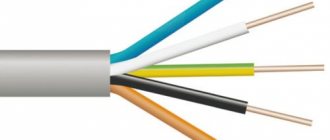
If color marking exists and is observed, then the neutral and protective wires should be:
Neutral wire N should be blue. Zero protective PE – yellow-green. The conductor combining the protective zero and the working zero PEN is yellow-green along the entire length of the wire, but at the end at the junction it is blue.
When coloring phase wires, the manufacturer is given a choice from a variety of color options. Here are the main ones:
Non-standard wire color options
Sometimes, due to incorrect labeling of colors by manufacturers, GOST standards have to be ignored. For example, you have 3 wires in a cable of different colors:
- blue
- brown
- black
In this case, you do the phase according to the rules, namely in brown. The neutral wire will be blue. But the black core will become grounding. In this version, the colors will at least resemble the Soviet standard.
Another of the “inconvenient” options for combining colors of cable cores:
- black
- blue
- red
To violate GOST as little as possible and be close to its requirements, make the phase black. Blue is zero, but red will be the protective conductor PE.
Just be sure to mark it at the end with yellow and green electrical tape.
What to do if the cable does not have a single color that resembles a phase wire? That is, the colors black, brown and gray are missing. Then choose for the phase the wire that corresponds as closely as possible to the brown color established by the rules. For example, red.
For two-core cables, in which the colors black and white are often found, also rely on GOST:
- black will be phase – L
- white – zero combined with grounding PEN
If a tap goes from a 3-phase 380V cable to a single-phase 220V network, then the outgoing core must be the same color as the power wire. When you do come across a cable with a missing core color, you can use colored digital cambrics.
At the ends of the wires, according to the phasing, you can put on multi-colored insulating thermal tubes or multi-colored electrical tape.
To avoid resorting to such methods, at the stage of purchasing and selecting a cable, pay attention to its color in advance.
Checking the correct connection
Unfortunately, not all electricians strictly follow the standards and make mistakes in choosing a conductor when making connections. Therefore, when hanging a chandelier, installing a socket or other electrical installation device, it is better to additionally check whether the insulation of each core corresponds to its purpose.
Mandatory checking of the neutral or phase is dictated by safety standards and the instinct of self-preservation: if you accidentally mix up the contacts during installation, you can get an unpleasant injury - an electrical burn
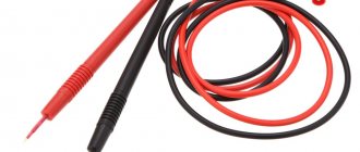
For identification, installers use two methods: the first is checking with an indicator screwdriver, the second is using a tester or multimeter. The phase is usually determined with a screwdriver, and neutral and zero are determined with measuring instruments.
How to use the indicator?
Even such simple devices as indicator screwdrivers are different. Some of them are equipped with a small button, others are triggered automatically when a metal rod and a current-carrying conductor or contact are connected.
But all models without exception have a built-in LED that lights up under voltage.
The indicator screwdriver is preferred by amateurs who do not have special qualifications. Professional electricians value accuracy, so they always have a tester with them.
A screwdriver is a convenient tool for identifying phase conductors. To find out whether the wire is working, use the metal blade of a screwdriver to gently touch the exposed wire.
If the LED lights up, the wire is energized. The absence of a signal indicates that it is ground or zero.
When using the indicator, you must adhere to the safety rules. Even if the screwdriver handle is insulated, it is recommended to wear protective gloves (with a rubberized inner layer), as when working with electricians in general.
The verification procedure is performed with one hand, therefore, the other is free. It is better to also use it - for example, to fix wires. But it is strictly forbidden to touch the exposed parts of conductors or metal objects located nearby (pipes, fittings) with your second hand.
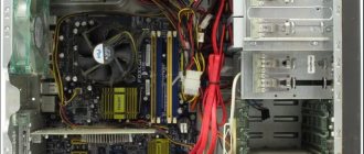
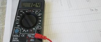
Rules for using the tester
An electrician's kit always includes a tester or multimeter. He has to work with the connection of conductors in electrical installations indoors and when assembling an electrical panel. If the wiring was installed a long time ago, marking the wires by color can be neglected.
Even if the insulation colors seem to be consistent, it is not a fact that they are connected according to all the rules.
Using the tester, you can find out not only the likelihood of connecting conductors to the electrical network, but also some parameters: current, resistance, voltage. Using a multimeter you can test diodes, check transistors, determine inductance
Before taking measurements, you should study the instructions that accompany all measuring instruments.
The procedure is approximately as follows:
- we set a value that is obviously higher than the expected voltage, for example, 260 V;
- connect the probes to the required sockets;
- we touch two conductors with probes - presumably phase and neutral;
- repeat the procedure with another pair of conductors.
The combination of phase-zero cores should produce a result close to 220 V. It will always be higher than the phase-ground pair.
There are both digital, modern instruments on sale, as well as outdated ones, with arrows and value scales. It is more convenient to use digital ones. Before installing electrical devices yourself, we recommend learning how to use either an indicator screwdriver or a multimeter - you should not rely only on the color of the wires.
The ability to use a multimeter will be useful for a home handyman to check the voltage in an outlet. Detailed instructions for using the tester are given in this article.
Color coding of wires
Color marking clearly identifies the purpose of the conductor in any power system.
Single-phase networks
Contains two power wires:
- linear (also phase) brown L1;
- neutral blue N.
Two-phase networks
They have three wires:
- linear L1, L2, colored brown and black, respectively;
- neutral wire N, painted blue.
Three-phase network
- Linear wires L1, L2, L3 brown, black, gray;
- neutral wire N is blue.
GOST R 50462-2009
Basic principles and safety principles for human-machine interface, execution and identification. Identification of conductors using colors and alphanumeric designations
This standard came into force on 01/01/2011. It replaced the previously valid GOST R 50462-92. The new regulatory document was developed based on the application of the International Electrotechnical Commission standard IEC 60446:2007. These documents establish rules for marking cable cores and busbars with certain colors and alphanumeric designations.
Compared to the canceled standard, the new document has significant differences. If the canceled regulatory document allowed the use of yellow and green colors separately to designate phase busbars, then the new standard does not allow this.
An attempt to bring the requirements (and traditions) of national standards to European standards led to a contradiction between the requirements of this standard and the requirements of the Electrical Installation Rules (ERI). For several decades, in accordance with the requirements of the PUE, phase busbars in AC electrical installations were designated yellow, green and red. This marking is applied to hundreds of thousands of operating electrical installations. But now the new standard requires the use of brown, black and gray colors for marking phase busbars for alternating current. The markings of zero working and protective conductors in all of the listed documents are the same.
Essentially, the introduction of this standard significantly complicated the identification of phase busbars in electrical panels by color and significantly increased the likelihood of electric shock to people. In most existing electrical installations, potential equalization buses are painted black. Now the phase conductor is marked with this color. Therefore, first of all, you should look at the installation locations of the tires and their relative position. And the color marking of phase busbars, which made it possible to identify them by color, is a thing of the past.
Arrangement of busbars in electrical installations with voltage up to 1 kV
In five- and four-wire three-phase alternating current circuits in electrical installations with voltages up to 1 kV, the busbar arrangement should be as follows:
- when positioned horizontally:
- one below the other: from top to bottom ABCN-PE (PEN);
- one after another: the most distant bus A, then the BCN phases, the closest to the service corridor - PE (PEN);
- in a vertical position:
- from left to right ABCN-PE (PEN) or
- the most distant bus A, then the BCN phases, the closest to the service corridor - PE (PEN);
- branches from busbars, if you look at the busbars from the service corridor:
- when positioned horizontally: from left to right ABCN-PE (PEN);
- for vertical placement: ABCN-PE (PEN) from top to bottom.
With direct current, the busbars should be located:
- busbars with a vertical arrangement: upper M, middle (-), lower (+);
- busbars with a horizontal arrangement: the most distant M, middle (-) and closest (+), when looking at the busbars from the service corridor;
- branches from busbars: left busbar M, middle (-), right (+), if you look at the busbars from the service corridor.