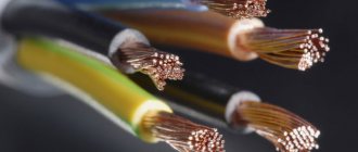
Correct identification of conductors is needed to solve various practical problems. If you correctly determine the “red black plus minus” correspondence, the normal functioning of the audio speakers will be ensured. Errors in power networks when determining “phase” and “zero” are accompanied by significant damage and emergency situations. The information presented below will help eliminate incorrect actions during installation work.
Color coding helps determine polarity when connecting test probes
Why do you need vein coloring?
Color coding of the wires allows you to quickly figure out what each wire is responsible for.
Novice craftsmen who are just learning the basics of electrical engineering cannot immediately determine whether the white wire is a plus or a minus. Coloring is important in identifying cores and is called marking. Color marking of conductors is a necessity, allowing the master to quickly figure out what each core is responsible for. With its help you can understand what color the neutral wire is and where the phase is located. It also makes electronic circuits easier to read. It is especially important to observe color markings when connecting to meters, machines, and devices. Without painting, it is difficult to figure out which device may have failed and which circuit it is connected to.
Manufacturers paint cables in certain colors established by the rules of electrical installations PUE. They strictly regulate which markings should be used for a particular core. In addition, it is important to understand that the positive and negative contacts in the DC circuit have their own colors. What color the positive wire is is also determined by the rules.
In the case of an unmarked cable of the same color, a label with information can be placed on the ends of the product (for example, on a heat-shrinkable tube).
Checking polarity
AC current can be tested using a multimeter or ohm voltmeter. Testing with a multimeter usually involves touching the positive and negative leads from the meter to the wiring being tested.
Voltmeter
Note! A flashing negative sign (“-”) before the digital readout on the meter indicates incorrect polarity.
Reverse polarity
If one of the outlets in your home is found to have reverse polarity, it is not difficult to correct the problem, but you will need to be careful to avoid electrocution. Before inspecting the wiring, you must turn off the household power supply. The positive wires, which are usually red or black, should be connected to a brass terminal. The neutral wires, which are usually white or gray, should be connected to a light-colored chrome terminal.
Important! If the wires are connected incorrectly, the polarity will be reversed, causing the current to flow in the opposite direction. This could result in electric shock to anyone who touches the device or outlet, and even damage to the device itself.
Features of core colors
To avoid errors, the PUE requirements describe the colors of all main electrical wires. If the commissioning work was carried out by an experienced electrician who follows the rules of the Electrical Installation Code and the relevant GOSTs, during independent repairs you will not need either an indicator screwdriver or other devices that determine the purpose of a particular core.
Color marking in electrical equipment according to GOST
Ground wire color
Modern standards regulate the yellow-green color of the earth. The coloring can be done in the form of transverse yellow-green stripes or as yellow insulation with one or two longitudinal green stripes.
Some manufacturers produce a ground wire that is bright green or yellow. In this case, it is not difficult to identify the ground, since such colors are prohibited to indicate the phase. Similar markings are used on electrical circuits. Letter designation – RE.
Some experts incorrectly call the ground the “neutral and protective” wire. This may confuse others; you need to understand that under this name it is the earth wire that is hidden. It is, by definition, protective, as it helps protect a person from electric shock in the event of an emergency.
Grounding
The yellow-green wire is grounding. In circuit diagrams, grounding conductors are marked with the letters PE. In some older houses there are PEN wires in which the grounding is combined with the neutral conductor. If the cable was pulled according to the rules, wires with blue insulation were chosen, and only the ends and places of twists were yellow-green (thermal tubes were put on them). The thickness of the “zero” and grounding may be different. Often the thickness of these two conductors is less than the thickness of the phase conductor; this occurs when connecting portable devices.
When it comes to laying electrical wiring in multi-storey buildings and industrial premises, the norms of PUE and GOST 18714-81 come into force, requiring the mandatory installation of protective grounding. Grounding must have minimal resistance to compensate for the consequences of faults on the line and prevent harm to human health. That is, compliance with the standards for color marking of PUE wires is of paramount importance.
Manual color marking
It is used in cases where during installation it is necessary to use wires with cores of the same color. This also often happens when working in old houses, in which electrical wiring was installed long before the advent of standards.
Marking of two-core wires
If the cable is already connected to the network, then to search for phase wires, electricians use a special indicator screwdriver - its body has an LED that lights up when the tip of the device touches a phase.
True, it will only be effective for two-wire wires, because if there are several phases, then the indicator will not be able to determine which one is which. In this case, you will have to disconnect the wires and use a dialer.
Next, you will need a set of special tubes with a heat-shrinkable effect or insulation tape to mark the phase and zero.
The standards do not require such markings to be made on electrical conductors along their entire length. It is allowed to mark it only at the places of joints and connections of the necessary contacts. Therefore, if there is a need to apply marks on electrical cables without markings, you need to purchase materials in advance to mark them manually.
The number of colors used depends on the scheme used, but there is still a main recommendation - it is advisable to use colors that eliminate the possibility of confusion. Those. Do not use blue, yellow or green marks for phase wires. In a single-phase network, for example, the phase is usually indicated in red.
Marking three-wire wires
When phase, zero and ground are determined, markings can be applied. According to the rules, a yellow-green colored wire is used for grounding, or rather a core with this color, so it is marked with electrical tape of suitable colors. Zero is marked, respectively, with blue electrical tape, and the phase is any other.
If during preventive maintenance it turns out that the marking is outdated, it is not necessary to change the cables. In accordance with modern standards, only electrical equipment that has failed can be replaced.
What does the blue stripe on the electrical wire mean? L and N in electrics - color coding of wires
Example: computer power supply or car wiring.
Expert opinion
Viktor Pavlovich Strebizh, lighting and electrical expert
Any questions ask me, I will help!
The marking is preserved along the entire length; sometimes cambrics or electrical tape are used at the connection points to better fix the element. If there is something you don’t understand, write to me!
What GOST and PUE say about color marking
The main document that you should rely on when producing or purchasing cables is GOST 31947-2012. Before its appearance, there was no uniformity and order in the field of color designation of electrical wiring.
Until now, in old houses you can find wires in the same sheath, the color of which cannot determine what is connected - “phase”, “zero” or “ground”.
Now it has become much easier to identify veins. Even without using a tester, you can determine which contact a particular core should be connected to - by the color of the polymer insulation. The above-mentioned GOST document states that the insulation of cable products should differ in color. A certain shade should cover the wire with a continuous layer - from beginning to end. It is impossible for one wire at the beginning of the bay to be blue and the end to be white; Intermittent painting is also prohibited.
The only vein that can have a two-color shell is the “ground”. Officially, it is assigned the green/yellow combination; these two shades cannot be used separately. The regulatory documents also contain recommendations for the use of various circuits for 3-core, 4-core and 5-core cables.
For example, when producing 3-core cables, the following combinations are welcome:
- brown – blue – green/yellow;
- brown – gray – black.
If the cable consists of 4 cores, then two standard color options are also recommended:
- brown – gray – black – green/yellow;
- brown – gray – black – blue.
The diagrams for a 5-core wire look like this:
- brown – gray – black – green/yellow – blue;
- brown – gray – 2 black – blue.
The blue color indicates the “zero” core.
It is not recommended to use only two colors - red and white.
There are special requirements for the distribution of colors of the grounding conductor: on any randomly selected piece of wire 1.5 cm long, one color must cover 30-70% of the insulation, the second color must cover the remaining area. The color must be applied firmly and be clearly visible.
Colors for 220V and 380V networks
Installation of single- and three-phase electrical networks is facilitated if the wiring is made with multi-color wire. Previously, a flat two-core white wire was used for single-phase residential wiring. During installation and repair, to eliminate errors, it was necessary to ring each core individually.
The production of cable products with colored cores in different colors reduces the labor intensity of the work. To indicate phase and zero in single-phase wiring, it is customary to use the following colors:
- red, brown or black – phase wire;
- other colors (preferably blue) – neutral wire.
The phase markings in a three-phase network are slightly different:
- red (brown) – 1 phase;
- black – 2 phase;
- gray (white) – 3 phase;
- blue (cyan) – working zero (neutral)
- yellow-green – grounding.
Domestic cable products comply with the standard for core coloring, so a multiphase cable contains differently colored cores, where the phase is white, red and black , the neutral is blue , and the ground is yellow-green conductors.
Core marking for electrical installation solutions
It is not for nothing that at the beginning of the article the idea was voiced that the color designation of conductors greatly simplifies the installation process. If you independently do electrical wiring in an apartment or private house, select wires according to the standards, when connecting electrical devices, installing automatic protection, distributing wires in junction boxes, you do not need to double-check where the phase, neutral, and ground are - the color of the insulation will tell you about this.
A few examples of electrical installations where marking is important:
- Depending on which electrical installations are connected and where the wires are sent next, the wires are connected in junction boxes
- For each core in the socket body there is a special contact. Typically the contacts, screw or clamp, are also marked
- The supply conductor is usually connected to the upper, fixed contacts, the ground - to the ground bus
- The simplest scheme: the neutral conductor is sent directly to the lamps, and the phase conductor is sent to the switch, from where it is also redirected to the lamps
There are cables with a large number of cores, the painting of which is not practical. An example is SIP, which uses a different method for identifying conductors. One of them is marked with a small groove along its entire length. The relief core usually performs the function of a neutral conductor, the rest play the role of linear ones.
To distinguish the cores, they are marked with tape, heat shrink, and letter designations, which are applied with multi-colored markers. And in the process of electrical installation work, a ringing is required - additional identification.
Phase color
When installing electrical wiring, it is the phase conductors that pose a particular danger. If a phase is touched, a person may receive an electric shock, which can be harmful or fatal. Painting in bright colors allows the master to determine that it is a phase conductor in front of him.
Usually the phase is colored red and black, but other colors can also occur (orange, brown, pink, purple, white, turquoise and others).
If the electrician does not know exactly what color the phase is, you can use the method of elimination. The neutral and ground wires have a strictly defined color, and then the remaining core is a phase.
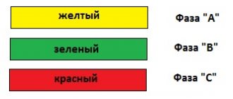
In the diagrams, the phase is designated by the Latin letter L. If there are several of them, a number is added - L1, L2, L3 for three-phase networks of 380 V. The designation A, B and C is also found in electrical networks with three phases.
Checking the correct connection
Unfortunately, not all electricians strictly follow the standards and make mistakes in choosing a conductor when making connections. Therefore, when hanging a chandelier, installing a socket or other electrical installation device, it is better to additionally check whether the insulation of each core corresponds to its purpose.
Mandatory checking of the neutral or phase is dictated by safety standards and the instinct of self-preservation: if you accidentally mix up the contacts during installation, you can get an unpleasant injury - an electrical burn. For identification, installers use two methods: the first is checking with an indicator screwdriver, the second is using a tester or multimeter. The phase is usually determined with a screwdriver, and neutral and zero are determined with measuring instruments.
How to use the indicator?
Even such simple devices as indicator screwdrivers are different. Some of them are equipped with a small button, others are triggered automatically when a metal rod and a current-carrying conductor or contact are connected.
But all models without exception have a built-in LED that lights up under voltage.
The indicator screwdriver is preferred by amateurs who do not have special qualifications. Professional electricians value accuracy, so they always have a tester with them. A screwdriver is a convenient tool for identifying the phase conductor. To find out whether the wire is working, use the metal blade of a screwdriver to gently touch the exposed wire.
If the LED lights up, the wire is energized. The absence of a signal indicates that it is ground or zero.
When using the indicator, you must adhere to the safety rules. Even if the screwdriver handle is insulated, it is recommended to wear protective gloves (with a rubberized inner layer), as when working with electricians in general. The verification procedure is performed with one hand, therefore, the other is free. It is better to also use it - for example, to fix wires. But it is strictly forbidden to touch the exposed parts of conductors or metal objects located nearby (pipes, fittings) with your second hand.
Rules for using the tester
An electrician's kit always includes a tester or multimeter. He has to work with the connection of conductors in electrical installations indoors and when assembling an electrical panel. If the wiring was installed a long time ago, marking the wires by color can be neglected.
Even if the insulation colors seem to be consistent, it is not a fact that they are connected according to all the rules.
Using the tester, you can find out not only the likelihood of connecting conductors to the electrical network, but also some parameters: current, resistance, voltage. With a multimeter you can test diodes, check transistors, and determine inductance. Before taking measurements, you should study the instructions that accompany all measuring instruments.
The procedure is approximately as follows:
- we set a value that is obviously higher than the expected voltage, for example, 260 V;
- connect the probes to the required sockets;
- we touch two conductors with probes - presumably phase and neutral;
- repeat the procedure with another pair of conductors.
The combination of phase-zero cores should produce a result close to 220 V. It will always be higher than the phase-ground pair. There are both digital, modern instruments on sale, as well as outdated ones, with arrows and value scales. It is more convenient to use digital ones. Before installing electrical devices yourself, we recommend learning how to use either an indicator screwdriver or a multimeter - you should not rely only on the color of the wires.
Determining polarity with a multimeter
Sometimes it happens that a new electrical device that needs to be connected does not have polarity markings, or it is necessary to re-solder the wiring of a damaged device, and all the wires are the same color. In such a situation, it is important to correctly identify the poles of the wires or contacts.
But if you have the necessary instruments, a logical question arises: how to determine the plus and minus of an electrical appliance with a multimeter?
To determine the polarity, the multimeter must be turned on in the mode for measuring direct voltage up to 20 V. The wire of the black probe is connected to the socket marked COM (it corresponds to the negative pole), and the red one is connected to the socket with the VΩmA marker (it is, accordingly, a plus).
After this, the probes are connected to the wires or contacts and the device, the polarity of which needs to be determined, turns on.
If the multimeter display shows a value without additional signs, then the poles are determined correctly, the contact to which the red probe is connected is positive, and the contact to which the black probe is connected will correspond to the minus.
If the multimeter shows a voltage value with a minus sign, this will mean that the probes are connected to the device incorrectly and the red probe will be a minus, and the black probe will be a plus.
If the multimeter used to measure is analog (with an arrow and a display with gradations of values), if the poles are connected correctly, the arrow will show the actual voltage value, but if the poles are reversed, then the arrow will deviate in the opposite direction relative to zero, that is, it shows a negative current value.
How to determine ground, zero and phase on wires if there are no markings
It is more difficult to determine in practice than in theory. Not all manufacturers comply with the standards. Therefore, when laying a two-phase 220 V network with grounding, you have to use a VVG cable with blue, brown and red colors. Combinations may be different, but without complying with regulatory requirements.
For your information. In old wiring from “Soviet times” there is no color marking. Identical white (gray) shells do not allow the purpose and correspondence of the lines to be known by simple visual inspection.
To avoid problems, it is recommended to carry out installation work using the same type of cable products. When color coding is not available, it should be created at the joints using insulating tape or heat shrink tubing. The latter option is preferable, as it is designed to maintain integrity for a long time.
Below are methods for determining phase and neutral wires with the advantages and disadvantages of each option. In any case, first clarify the network parameters. In old houses, for example, a two-wire connection scheme with a single working and grounding conductor is often used.
TN-S grounding diagram. The figure shows a modern network with separate grounding and working zero connections. It is possible to connect three- and single-phase loads.
Determining the phase using an indicator screwdriver
Touching the tip of such a device to the phase wire closes the current circuit. This is accompanied by the warning lamp or LED lighting up. A built-in resistor limits the current to a safe level.
Design of an indicator screwdriver.
Advantages of the indicator:
- minimum cost;
- compactness;
- reliability;
- durability;
- autonomy;
- good protection from adverse external influences.
The disadvantage is the limited measurement accuracy. Under certain conditions, false positives cannot be ruled out.
Determination of ground, zero and phase using a test lamp
To reproduce this technology, you need to prepare a simple design. An incandescent lamp designed for the appropriate mains voltage is screwed into a standard socket. Connect wires of sufficient length to perform work operations in a specific location. Next, connect one of the wires to the known zero line. Others sequentially check other cable cores. Lighting of the lamp indicates the presence of a phase.
Using a measuring device
When checking a 220 V household network, you do not need to know how to determine the polarity. The power supply is organized using alternating current, so set the multimeter switch to the appropriate position. Touching the phase-zero (phase-ground) wires with the probes is accompanied by an indication of the corresponding voltage (≈220 V). The potential difference between the neutral conductor and ground is minimal.
When checking an old two-wire circuit, one of the probes touches the reinforcement in a concrete slab, a radiator of a heating system, or another grounded element of a building structure. When switching to constant voltage, the multimeter will show where the plus and minus are. In the absence of reliable information about the electrical parameters in the circuit, they begin with the maximum measurement range with a sequential transition to smaller values with insufficient accuracy.
Such a “device” is useful for testing DC circuits in the absence of specialized measuring instruments. Bubbles near the negative wire are the release of hydrogen during the electrolysis reaction. The area near the plus will take on a greenish tint after a few minutes.
Using LED
You can create a control device with your own hands by analogy with an indicator screwdriver. Instead of a light bulb, install AL 307 or another LED with similar characteristics. A 100-120 kOhm resistor with a power of 1-2 W is added in series to the circuit.
How to correctly determine the polarity on wires in a car
If the voltage on the car is checked, the course is set to search for a constant one. 20W is the correct setting if you are testing the battery. Therefore, you need to adjust the dial to the desired range/setting and connect the probes to whatever component you want to get a reading for.
You may be interested in this: How to find out amperage
How to check a headlight with a multimeter
Multimeter
To check the headlight wiring, you need to find the ground wire. There are 2-4 wires coming from the connector that connects to the light bulb. Where there are two or three wires, only one of them is ground, while four-wire connectors will have two grounds.
To test the wires on the headlight, you need to set the multimeter to resistance. You can place one of the probes on the ground and the other on the negative pole of the car battery.
Note! If continuity is not read, then there is a problem with the ground wire, meaning it needs to be replaced.
How to Test a Car's Ground Wire Using a Multimeter
To test ground wires, start by measuring resistance. Test along the wiring to check the reading is 5 ohms or less. If it exceeds, you will need to check the wire further. You need to switch the multimeter to constant voltage and turn on any electrical part that is having problems. It's worth double-checking the wire to make sure the reading doesn't exceed 0.05V. If it does, you'll need to use a different ground location or use a tie strap.
How to Check if a Fuse Has Blown Using a Multimeter
Troubleshooting a fuse using a multimeter is extremely easy. You need to set the multimeter to the lowest ohm setting and place the probes on both sides of the fuse covers. Fuses do not have polarity, so the contacts used will not show values.
Circuit breakers
Note! If the resistance value is very low, then the fuse is working perfectly. If the resistance value does not change after connecting the contacts, the fuse has blown.
You can also test the fuse using a test light. You need to turn on the key and touch both sides of the fuse with the tip of the test light. If it lights up, the fuse is good. If it does not light up, the fuse needs to be replaced.
How to use a multimeter from a car battery
If you're having trouble starting your car, one of the most common reasons is a weak battery. This is something that can be easily checked using a multimeter, which will also give an accurate idea of how much charge the battery actually has left. Testing your car battery first is a great way to rule out a likely cult for many electrical problems.
When testing a car battery, you need to check the voltage by setting the multimeter to 20 V DC. It is necessary to connect contacts to both terminals of the battery that match the color. It is better to turn on the headlights to get accurate information regarding the charge.
Important! The headlights must be turned on when the engine is stalled.
In most cases the reading will be somewhere between 11.8 V and 12.6 V. The higher the voltage reading, the more charge there is in the battery. A reading of 12.5V means the battery is almost fully charged, while a reading of 11.9V means the battery should be replaced soon.
You may be interested in this Features of the DRL 250 lamp
Checking the charger
Electronic devices use adapters to convert alternating current supplied from wall outlets to direct current. Once converted to direct current, current flows in one direction, hence the term direct current.
What color is the positive wire on the charger?
Note! One wire is positive, which conducts current to the device, and the other is negative, which completes the circuit. The direction of flow is called polarity and is marked on chargers using a diagram. If there is no diagram on the charger, it is worth checking the polarity.
The color polarity of the charger wires does not matter.
To determine if the charger is fit for use, do the following:
- Connect the charger to a power outlet.
- Turn on the multimeter and set the settings to DC voltage. Most multimeters indicate this setting as VDC.
- Insert the red positive contact into the hole in the charger tip.
- Touch the black negative terminal and the outer metal part of the charger tip.
- Monitor the multimeter readings. You may see a positive or negative number indicating the DC output voltage of the charger. If the number is positive, then the polarity on the inside of the charger tip is positive. If the number is negative, then the polarity inside is negative.
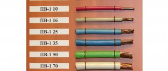
Wire Classification Options
The typical cable name contains letters and numbers. By decoding these symbols you can find out the main characteristics of products in this category:
- conductor (shell) materials;
- number of cores;
- cross-sectional area;
- Extra options.
Example of decoding (AVBbv-ng):
- A – the core is made of aluminum (copper is not marked);
- B – insulating shells are made of PVC;
- BB – protection against mechanical damage, made of steel tape without a damping gasket;
- ng – components that prevent combustion have been added to the polymer shell.
Ground wire color
By modern standards, the ground conductor is yellow-green. It usually looks like yellow insulation with one or two longitudinal bright green stripes. But there are also transverse yellow-green stripes in color. This color can be grounding.
In some cases, the cable may only have yellow or bright green conductors. In this case, the “earth” has exactly this color. It is displayed in the same colors on diagrams - most often bright green, but it can also be yellow. Signed on circuit diagrams or on ground equipment in Latin (English) letters PE. The contacts to which the “ground” wire must be connected are also marked.
Sometimes professionals call the grounding wire “neutral protective”, but do not be confused. This is an earthen one, and it is protective because it reduces the risk of electric shock.
What color is the neutral wire?
Zero or neutral is blue or light blue, sometimes blue with a white stripe. Other colors are not used in electrical engineering to indicate zero. It will be like this in any cable: three-core, five-core or with a large number of conductors.
What color is the neutral wire? Blue or light blue. “Zero” is usually drawn in blue on diagrams and signed with the Latin letter N. Experts call it a working zero, since, unlike grounding, it participates in the formation of the power supply circuit. When reading a diagram, it is often defined as "minus", while the phase is considered "plus".
Wire colors in electrical wiring
Battery polarity
The color identification scheme is convenient not only for installation. As a rule, different contractors install and operate electrical wiring. Compliance with standards prevents errors during repair work and in the modernization process.
Something to remember! Domestic standards have changed several times over the past decades. Currently, the markings discussed above are used.
Color of zero working and zero protective wires
The color options for the shells will help you recognize the intended purpose of the conductors:
- blue – working zero;
- transverse or longitudinal combinations of yellow and green stripes - protective zero;
- main blue with a change to a combination of yellow and green stripes at the junctions - combined working and protective zero.
For your information. The last universal option can be done in the reverse way. The main part of the line is created from a combination of yellow and green stripes, with blue color applied at the junctions.
Color of wires plus (+) and minus (-) in DC networks
Is the red wire positive or negative? Such questions arise when working with DC electrical circuits.
Red
To remember which plus is red or black, they use the name of a well-known international organization - the Red Cross. This phrase suggests that red means plus.
Black
Black color indicates the negative conductor. These markings can be seen on typical household equipment:
- power supplies;
- audio, video equipment;
- other devices with electronic software control units.
Plus
The polarity of conductors must be observed when repairing standard electrical equipment of cars. In some situations, confusion with plus and minus is accompanied by a violation of the functional state.
Minus
The high power of connected consumers increases the responsibility for performing repair and adjustment work. In such situations, it is necessary to eliminate errors in determining polarity. Strong direct current is used to supply electricity:
- warehouse and municipal transport;
- lifting mechanisms;
- sensors and automation.
Charger wire polarity by color
Let us assume that you have come across some kind of constant voltage power supply or battery. It does not indicate where the plus is and where the minus is. Yes, the matter can be quickly resolved with a multimeter, but if you don’t have one at hand, and we urgently need to start the car or power some trinket? An incorrect connection can damage the power source itself, or the device or unit being powered. This is where it is important to determine the polarity of the power source using improvised means. In this article I will tell you about three simple ways. Method number 1.
Letter designation of wires
Color markings can be supplemented by letters. Partially the symbols for the designation are standardized:
- L (from the word Line) - phase wire;
- N (from the word Neutral) - neutral wire;
- PE (from the combination Protective Earthing) - grounding;
- “+” - positive pole;
- “-” — negative pole;
- M is the midpoint in DC circuits with bipolar power supply.
To designate the protective grounding connection terminals, a special symbol is used, which is stamped on the terminal or on the device body in the form of a sticker. The grounding symbol is the same for most countries in the world, which reduces the likelihood of confusion.
In multiphase networks, the symbols are supplemented by the serial number of the phase:
- L1 - first phase;
- L2 - second phase;
- L3 - third phase.
There is marking according to old standards, when the phases are designated by the symbols A, B and C.
A deviation from the standards is the combined phase designation system:
- La - first phase;
- Lb - second phase;
- Lc - third phase.
In complex devices, additional symbols may be found that characterize the name or number of the circuit. It is important that the markings of the conductors match throughout the entire circuit where they are involved.
Letter designations are applied with indelible, clearly visible paint on the insulation near the ends of the cores, on sections of PVC insulation or heat-shrinkable tube. Connection terminals may have marks that indicate circuits and power polarities. Such signs are made by painting, stamping or etching, depending on the material used.
What color are the poles in the wires?
The protective neutral cable connects the protective ground and N-neutral cables. These types require double grounding along the line. The marking of electrical wires is the same as for the protective conductor, yellow-green. Blue color was also used in older installations, but nowadays such markings are rare. It is much more common to see installations marked with alternative yellow and green stripes.
Note! The very tip of the protective neutral cable is usually marked blue. Neutral cable is found in very old electrical installations
It was used in cases where circuits did not yet have neutral and protective cables. The installation only had phase and ground neutral wires, which could be identified by their blue color. Today the neutral conductor is no longer used in electrical installations
The neutral cable is found in very old electrical installations. It was used in cases where circuits did not yet have neutral and protective cables. The installation only had phase and ground neutral wires, which could be identified by their blue color. Today, the neutral conductor is no longer used in electrical installations.
Green cable with positive potential
Green color is for electrical cables with positive potential.
In electronic devices, positive charge flows in the red wires, negative charge in the black wires.
Additional marking of wires
If the purchased cable has conductors of a color that does not comply with the standards, or the wiring has already been laid and is incorrectly marked, additional identification must be carried out.
Additional marking of wires.
During the electrical installation process, the ends of the wires are marked using heat-shrinkable tubing or colored insulating tape. Additionally, the letter designation of the cores can be applied to the wire or a tag attached to the wire:
- L – phase.
- N – neutral (working zero).
- PE – ground (protective grounding).
How to check the correct connection of wires
Very often, to connect additional sockets, lighting fixtures or household appliances, you need the ability to determine phase, neutral or grounding. This will prevent short circuits or shock hazards. Also, if there are errors in the connection, the device is guaranteed to fail.
In new wiring, the colors of the wires must correspond to their purpose. In cases of old wiring, you should understand the purpose of each line and attach a tag or other mark to it.
Security measures
When working with electric current, the following precautions must be taken:
- Use devices only for their intended purpose;
- Do not turn on equipment with damaged wires and plugs, do not use faulty sockets;
- Do not touch wires or outlets with wet hands or while standing on a wet floor. When working in a room with high humidity, you need to use rubber gloves and a mat;
- Do not bend wires and cables;
- Before starting work, it is worth disconnecting the entire network;
- If the equipment sparks or starts to catch fire when turned on, do not touch it. It is necessary to turn off the power through the panel;
- If you have any doubts or fears, it is better to contact a specialist or choose a safer option, for example, determining the polarity using a potato rather than connecting to a device.
Most often in batteries, the red wire indicates positive, the black wire indicates negative, and there are no problems when working with electricity. However, today many countries use their own color designations or abandon them altogether, leaving the wires uniformly white. In order not to create emergency situations, it is worth checking the polarity first.
How to check the correctness of the markings in the apartment?
Relying on color alone is not recommended. Before starting work, it is recommended to check their belongings. A special screwdriver is used for this.
The LED on it lights up when you touch the phase. There will be no problems with a two-core cable, because the second one will be zero. For three-wire, use another tool - a multimeter or tester.
What kind of lighting do you prefer?
Built-in Chandelier
The switch is set on a scale greater than 220V. This indicator or even less should be displayed on the screen, because these are our realities.
To use a multimeter, it is worth considering that when ringing a phase-ground pair, the readings are lower than when ringing a phase-zero pair.
When connecting wires, try to use wires of the same color. Try not to confuse them so as not to face disastrous consequences - injuries or fires.
How to determine wire polarity
You will need
- multimeter, 3 volt battery, indicator screwdriver, test lead.
Instructions
To determine the polarity of the wires coming out of the charger, turn the multimeter into DC voltage measurement mode up to 20 volts, insert the black wire (negative) into the COM jack, and the red (positive) wire into the VΩmA jack.
Connect the probes to the terminals of the charger and turn it on. If a minus sign appears on the multimeter display, then the polarity of the connection is opposite, that is, the red probe is connected to the negative terminal, and the black probe is connected to the positive terminal of the charger.
If there is no minus sign, the terminals correspond to the probes connected to them.
To check the polarity of the speakers, briefly touch its wire
mi from a 3 volt battery. When the speaker cone moves outward, the polarity of the speaker terminals matches the polarity of the battery.
When moving inward, the polarity of the speaker terminals is opposite to the polarity of the battery.
Important
Power wires in branded car radios are easily distinguished by their color, which always matches its wire. Black color on the wire
, connected to ground or the general “minus” of the power supply, the red wire is the “plus” of the power supply, connects to the ignition switch, the yellow wire also belongs to the “plus” of the power supply, but is connected to the battery.
Self-labeling
There are times when markings are erased or missing/mixed up. Then, after ringing each conductor, you should independently indicate which core is responsible for what.
If sections of the wire are completely replaced, you can purchase cables of the required color. If it is not possible to purchase a suitable shade, you can make a mark on the ends using colored electrical tape or heat shrink tubing. The rules allow marking the conductor not along its entire length, but only at the points of connection to the busbars.
Features of working with electrical wires of different colors
There are cases when knowledge of phase and zero is not necessary. For example, when connecting a new outlet or replacing an old one. When connecting a plug to it, the polarity is not important and does not affect the performance of the device.
In situations where you need to connect a switch to a chandelier, you need to find out the phase and zero. The phase conductor is connected directly to the switch, and only the neutral conductor is connected to the light bulbs. Otherwise the switch will not work.
The use of conductors of different colors made the work of the craftsmen much easier and sped up the installation process. Also, the color designation made it possible to increase safety when working with live conductors.