GOST 18690-2012 stipulates that each cable product is subject to symbolic marking. This makes product selection much easier. Thanks to this parameter you can determine:
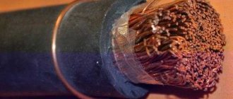
- what the wire consists of and the number of cores. Conductors are mainly made of copper; they can be single-core or stranded;
- What does the insulating layer consist of? In most cases, PVC material is used;
- The marking also indicates the cross-sectional area of the wires, thanks to which the internal resistance can be determined.
How cable marking is indicated
Please note! There are many tables on the Internet that help you understand the names of the wires. Today there are more than 300 designations with which Russian and imported wires can be marked. Below you can read a detailed breakdown of the most common products.
Purposes of wire markings
The designation of cable lines and wires is carried out in order to simplify installation work, repairs and preventive maintenance of objects during operation. To improve safety measures that reduce the likelihood of accidents and injuries to operating personnel.
- the number and cross-section of wires in the cable;
- type of insulation;
- what metal are the wires made of?
- about the material of the outer insulation layer and much more.
All these measures are insufficient to achieve maximum safety and do not provide maintenance personnel with information about the purpose of cable lines and individual sections of electrical wiring. During installation in switchgears, additional markings are applied to cables and wires, which display not only the characteristics of the cable, but also its purpose in a given circuit.
A list of main parameters is indicated:
- cable brand;
- from what object does it come;
- length;
- appointment and other data as required.
To make marking convenient and quick, several methods have been invented for wires with different characteristics, diameters and insulation. Marker designs vary, but all provide clear, long-lasting writing.
Main variety
Today, cords, cables and wires are used for electrical installation work. Before deciphering the markings, it is necessary to understand what these products are and what their differences are.
Wires
A wire is an electrical product consisting of one or more wires twisted together, without insulation or insulated. The core sheath is usually light and not made of metal (although wire wrapping is also common).
Such products can be used in electrical installation work (for example, installing electrical wiring in a wooden house), as well as in the manufacture of electric motor windings. Today there are wires with copper and aluminum conductors. The copper version quickly oxidizes in open space and has a high price, but at the same time it is capable of passing through higher current loads. In addition, copper is more elastic, which means it will not break as quickly. Aluminum ones are more fragile and are not connected to copper ones (except perhaps through terminals), but for that they have a low cost. Today, aluminum wiring is used less and less.
It should also be noted that the contacts may be insulated or bare. The latter option is used for power lines. An insulated wire can be protected or unprotected. Protection is provided by another layer of insulation (made of plastic or rubber), which covers the sheath of the cores.
The last classification is carried out depending on the purpose: mounting, power and installation. The mounting wire must be copper; it is used, as a rule, to connect elements of an electrical circuit in a switchboard, as well as to connect circuits in radio equipment. Power (as well as installation) is better known to us, because used outdoors and indoors.
Cables
An electrical cable is a product made up of several wires that are located under one insulating sheath (PVC, rubber, plastic). In addition to this shell, there may be additional protection - an armored shell made of wire or steel tape, which must be indicated in the marking.
There are 5 main types of electrical cables:
- power;
- control;
- For driving;
- for communication;
- radiofrequency.
Let us briefly consider the conditions of use of each product.
Power is used to transmit electricity in power and lighting electrical appliances. There are products of various types and purposes. Power cables are mainly used for external (both overhead and underground) and internal electrical wiring (in residential and non-residential premises). Power cables can have both aluminum and copper conductors. It is recommended to give preference to the latter option. The insulating layer can be PVC, paper, rubber, polyethylene, etc.
The control is used for the operation of electrical devices that transmit an information signal to control any devices. This type can also be with aluminum and copper conductors.
The control cable is a copper electrical conductor with a protective shield. Used in various automation systems. The protective screen serves to remove interference and also protect against mechanical damage.
A communication cable is used to transmit information using currents of various frequencies. Transmission of local communication lines is carried out by low-frequency conductors, and long-distance lines - by high-frequency ones.
RF cable is used in radio engineering devices. The main purpose is the transmission of video and radio signals.
Cords
Cord for household electrical appliances
So we have figured out the main differences between all three types of electrical products. We hope that the information was accessible to you. We also recommend watching the video, which provides this information more clearly:
Main characteristics and differences of conductors
General Differences
All conductors may differ in the following ways:
- Cross section. There are cores with a cross section of 0.35 mm2. up to 240 mm.sq.
- Manufacturing material: copper, aluminum, aluminum-copper (a special composite of two metals).
- Rated voltage (for example, can withstand 220 or 380V).
- Number of cores (single-core or stranded).
- Insulation material (PVC, rubber, paper).
- Protective shell material (rubber, plastic, metal).
Wire and cable marking methods
Depending on the conditions and capabilities, availability of equipment and material, installers select the optimal marking options:
Before installing the wire
- PVC cambrics (tubes) of various diameters with inscriptions, you can additionally wrap them with transparent tape for reliable fastening and protection of the inscriptions;
- Heat-shrinkable insulating tubes;
- The most accessible and cheapest way is to make an inscription on a thick paper tag, place it on the cable and wrap it with transparent tape.
These methods ensure a tight fit to the cable sheath and eliminate the possibility of marker breakage when pulling through pipes and other installation work.
After installing the wire
When wires and cables are inserted into distribution devices, marking is done in the following ways:
- Before connecting the wires to the contacts, you can use PVC casings and heat-shrinkable tubes;
- Self-laminating markers are self-adhesive, on one side the plate is not transparent, on the other side there is a matte surface for inscriptions. The tag is glued to the wire insulation and wrapped with transparent self-adhesive tape, almost like tape. The materials of the plates and glue can withstand high temperatures and are resistant to aggressive environments.
- Tags are sometimes this method is the most optimal, they are made from polymers of different formats, several ways of attaching to the cable sheath. Plastic is able to withstand high temperatures while maintaining inscriptions on its surface. The dimensions of the tags and the content of the inscriptions comply with the requirements of the PUE, PTE EP, SNiP;
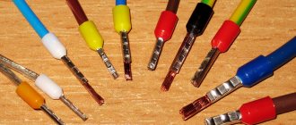
- For small-diameter wires, flags made of a polymer plate are used with inscriptions of standard designations, which are established by the guidelines for the design of electrical equipment;
- Self-adhesive nylon markers;
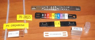
- Sleeves and containers consist of two components, a plastic carrier is attached to a wire (container), into which a polymer tape (marker) is inserted, and the necessary information is printed on it with a special printer;
- Clips and locking rings with pre-printed values, these can be individual numbers or letters, short content of 1-3 characters. This technique does not require the use of printing devices.
Rings RU Clips RA Clips R
| Type | Profile | Description | Dimensions |
| PA | Closed profile rings for medium and large diameter wires. | 4 sizes Ø 1.3 - 16.0 mm Section 0.2 - 70.0 mm2 | |
| PY | Closed profile rings for small diameter wires. | 1 size Ø 1.0-2.0 mm Section 0.2 - 0.7 mm2 | |
| PC | Open profile clips for fixed wires. | 5 sizes Ø 2.4-7.2 mm Section 1.0 - 10.0 mm2 | |
| PK | Rings for PKH plate with clamps (to be ordered separately). There is an analogue made of steel. | For wires and harnesses of any diameter |
Stage 1. Laying cables
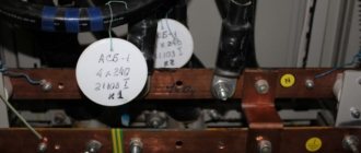
At this stage I stretch the cables from the shield to the boxes. As I wrote above, I wrap the ends with white electrical tape, on which I write the abbreviated name of the consumer (group) and put a serial number.
Signed cables arrive at the installation site of the shield
I carefully write down the name and number in the list near the shield.
List of consumer groups near the electrical panel (draft, if I had known that the photo would go to the website, I would have tried carefully))
Then it is better to duplicate this list in your notebook, since the rough draft on the wall may disappear when hard-working plasterers and painters appear.
The value of this list when the electrical panel is finally connected will be approximately the same as the value of the map in a pirate chest.
By the way, don’t be lazy (or instruct an interested person) to then transfer the names of power consumption groups to the panel, directly under each machine. This can be done with an ordinary thin marker, or you can go further - print the inscriptions on a printer. Otherwise, the leaf will definitely be lost, and in a year or two you will have to click the machines or ask the locals “What is this?”
Electrical panel with a leaf. Be sure to transfer the inscriptions to a permanent basis!
Printing devices and instruments
To apply inscriptions to marking elements, special devices have been developed, which can be divided into several types:
Portable automatic and semi-automatic devices
Canon MK 1500 printer
One of the modern devices for automatic printing on stickers, PVC casings and heat-shrinkable tubes is the Canon MK 1500 printer.
It is possible to select several types of fonts and set cropping modes at different intervals. Printing speed is 2.5 cm per minute, on a 20 mm tube you can print 35 markers per minute with 5 full-size characters.
Hotmarker M-3E
The Hotmarker M-3E printer prints characters on cables, casings and flat tapes using the hot stamping method. The printer's heated dies press the ink into the cable sheath. The matrix has the shape of a wheel, on which there are 10 + space symbols, a total of 7 matrices, this allows you to form thousands of combinations. This printer is capable of marking products with a diameter of 13 mm.
Stationary printers
Brady LabelMark
Used in large-scale production where it is necessary to mark large volumes of products with different types of markers. Brady's software allows LabelMark to quickly change from one program to another. Within 6.5 seconds, it prints characters and sticks a tag on the cable.
The program is placed on a regular PC and transferred from it to the printer. To operate the program and operate the printer, no special highly qualified training is required. The device has a high print resolution, up to 300dpi, which allows you to print small fonts and clear images of logos. Symbols are applied to wires with diameters of 1.5-15.2 mm, maximum marker dimensions 50.8 X 50.8 mm.
| Specifications | ||
| Printing technology | thermal transfer | |
| Print Resolution | 300 dpi (300 dpi) | |
| Production cycle duration, seconds | 4,5 — 6,5 | |
| Minimum wire diameter, mm | 1,52 | |
| Maximum wire diameter, mm | 15,24 | |
| Maximum print width, mm | 50,8 | |
| Maximum print length, mm | 41,3 | |
| Maximum label width, mm | 50,8 | |
| Maximum label length, mm | 76,2 | |
| Minimum label width, mm | 6,35 | |
| Minimum label length, mm | 19,05 | |
| Ribbon outer diameter | 68.58 mm | |
| Fonts, Barcodes, Graphics | Printing fonts, barcodes and graphics are consistent with LabelMark™'s label creation capabilities . For more information on this issue, check out LabelMark™ software. | |
| Interfaces and connectors | USB, Serial RS-232C, Ethernet, PCMCIA, CompactFlash | |
| Memory | Built-in 4Mb Memory expansion 32Mb RAM using PCMCIA or CompactFlash® | |
| Dimensions, mm | 571.5 x 368.3 x 450.9 | |
| Weight, kg | 38,5 | |
| Operating temperature | from 10° to 41° C | |
| Storage and transportation temperature | -18° to 60° C | |
| Humidity | from 20% to 80% without condensation | |
| Nutrition | 90-264 V AC, at 47-63 kHz | |
Office laser printers
Used when printing on sheets of self-adhesive stickers or regular sheets of A4 paper. Tags are placed on the cables and wrapped with transparent tape. This is a simple and cheap way for small volumes of marking.
Tip #1. Do not buy expensive marking equipment if you are not professionally involved in electrical installation work. Use low cost labeling methods.
Insulation type, armor and protection
The decoding of the cable abbreviation should be carried out taking into account generally accepted standards.
Core material
There are only 2 options here:
- absence of a letter - copper (copper wire does not need any designation);
- “A” is a letter designating conductors made of aluminum.
The data from this table will help you decipher abbreviations and abbreviations.
| Letter designation of insulation material (2nd position) | |
| IN | This type of insulation is made of polyvinyl chloride (in other words, PVC). |
| P | Polyethylene was used in the manufacture of insulation. |
| R | Rubber is used for insulation. |
| HP | Nairite (non-flammable rubber) |
| C | Film insulation (used in the manufacture of installation wires) |
| G | The protective layer is completely absent (bare). |
| F | Fluoroplastic |
| TO | This letter designates the control cable (its purpose). |
| KG | Flexible cable |
| A | Made of aluminum. |
| P | Protective sheath – polyethylene hose |
| Pu | Reinforced polyethylene hose |
| WITH | Lead sheath |
| R | Made from rubber |
| IN | PVC (polyvinyl chloride) sheath |
| BbG | The armor consists of a profiled tape made of steel. |
| Bn | The armor consists of steel strips equipped with a protective cover; the material does not support combustion. |
| IN | Polyvinyl chloride used |
| Bl | Armor made of steel tapes, Bl |
| D | The braid is made of double wire. |
| TO | Round steel wires, which are enclosed in a steel cover, are used as armor. |
| P | Flat steel wire armor |
| D | A braid consisting of two wires is used. |
| E | Screened cover (often this type is represented by aluminum foil) |
| G | There is waterproofing (protects against corrosion) |
| IN | This letter designation can have 2 decodings. If it is in the middle, the protective sheath is made of PVC, the second variety is the placement of “B” at the end. This means that the cover is made of paper. |
| ABOUT | Wires covered with insulation and connected using a winding |
| N | Cover made of non-flammable material |
| Shp | Protection is provided by a polyethylene hose. |
| Shv | Vinyl hose |
| Shps | Self-extinguishing polyethylene |
- MK – means main cable;
- Ш – mine;
- MK - these letters are applied to the main cables;
- RK – abbreviation indicates radio frequency cable;
- T – intended for telephone communication;
- O – optical type;
- KS – cable products for communication;
- KM – characterizes the combined main view;
- VK – these letters characterize intrazone communication cables;
- PPP - insulation is presented in the form of a three-layer film (film-pores-film).
- Z – in this type of cable, the cores are twisted into a “star” four.
Basic requirements for marking wires in switchgears (switchgears) and switchboards
Clause 1.1.30 of the PUE states that all wires in the control panel must correspond to the alphabetic, digital and color designations. The presence of a color designation does not exclude the installation of numbers and letters. It is allowed to apply markings not along the entire length of the line, but only at the connection points.
Marking begins with compliance with the rules during the installation process, when connecting wires according to the color of the insulation. This is the most clear example, which allows operating personnel to quickly navigate the purpose of each individual wire in the circuit. Sometimes cables with wires of the same color are used; in these cases, it is possible to paint the ends of the wires, put on cambrics of the corresponding color, or it is more practical to install a heat-shrinkable tube with alphabetic and digital values already applied. The length of the marker tube must be at least 2.5 cm.
Wire marking by color
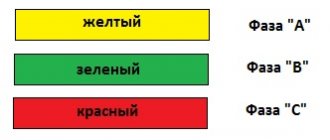
In three-phase networks, each phase is designated by the letters A, B, C, but in apartments and private houses single-phase power supply circuits are used, so there is no point in specifying which phase of the substation your panel is connected to.
Letter designations:
- The phase wire is marked with the letter “L”;
- The neutral wire is designated by the letter “N”;
- Grounding wires are marked with a symbol
- In circuits according to TN-CS system standards, it is allowed to connect the grounding conductor to the neutral wire. In such cases, “PEN” is written on the label.
- In DC power supply circuits, for individual consumer devices the polarities “+”, “-” and the voltage in volts “12V or 24V...” are indicated.
Marking DC circuits
How to find zero and phase
At home, even without special instruments and devices, it is possible to determine in a regular outlet which of the two wires is a phase and which is a zero. In this case, an electric lamp or an indicator screwdriver is used.
Checking with an electric lamp
To find zero and phase, just take an ordinary socket with a light bulb and screw two wires into its regular places. Then connect one of these wires to the grounding blades in the socket, and the second to either of the two power connectors.
The phase connector will be the one to which the light bulb will light up when connected. This happens because, according to the Electrical Installation Rules (PUE), in the input electrical panel, the neutral wires of all sockets must be connected to the ground wires of the same sockets. A separate earth bus must be connected to a protective ground loop. This is what ensures the presence of a reliable zero in the entire energy supply chain of the house.
Electric lamp
Note! It is permissible to carry out such procedures independently only in cases where there is nowhere to wait for qualified help, as well as in the event of an emergency (fire, short circuit, person under voltage). Do not forget that electric current is very dangerous.
Don't risk your health and your life over a light bulb!
Indicator screwdriver
In order to determine the phase in an alternating current network with a voltage of 220V - 230V, you can use a household voltage indicator - an indicator screwdriver. It is sold in almost any hardware store and is (depending on the design) very inexpensive.
An example of a working indicator screwdriver
As a rule, such tools do not have instructions for use, so in order to avoid electrical injury, you should remember a few simple rules that apply to any tool that comes into contact with live parts:
- Use the tool only for its intended purpose (it is prohibited to use the voltage indicator - indicator screwdriver - as an ordinary screwdriver for tightening/unscrewing screws, self-tapping screws, screws, etc.)
- Before using the tool, you should carefully consider the condition of the insulation on the handle and tip (applicable to any screwdrivers, including indicator ones). Do not use the device under any circumstances if the insulating coating is chipped or missing altogether.
- It is necessary to check the functionality of indicator devices on electrical installations that are known to be energized (for example, in an extension cord into which a working electrical appliance is connected).
Screwdriver with insulated blade
If there is any doubt about the functionality of the indicator, it should be considered faulty and the electrical installation functional. There are also more accurate and safer instruments for determining the presence of voltage in the network - these are multimeters, current clamps, volt-ampere phase meters (VAF) and others.
Multimeter
In everyday life, as a rule, simple multimeters are used. They are able to show the presence of voltage in the network and its value. It is much safer to use these devices to determine the phase, since their probes have a dielectric handle. The principle of determination is the same as in the case of a cartridge - it is enough to apply one probe to the ground contact of the socket, and place the second one on one of the two contacts of the socket.
Multimeter example
Electricity (according to Newton's second law) does not appear from nowhere and does not go to nowhere. It is produced, transported and consumed before our eyes. We need to know where it comes from, how it gets to us and in what form. Everyone should understand that in household use there are wires that can harm human health, and there are also those that are completely harmless, so a little knowledge and a minimum of instruments are needed to identify and distinguish between these wires. But it is better to trust any manipulations with electricity to a professional - a qualified specialist, in order to avoid disaster.
Features of digital wire designation
Digital designations in distribution boards require separate consideration. According to the requirements of the PUE, the distribution of power supply circuits in the distribution board is carried out in groups. Separate areas are fed from the group; these can be different objects:
- No. 1 lighting;
- No. 2 sockets;
- No. 3 air conditioner;
- No. 4 heated floors;
- No. 5 Boiler for heating water;
- No. 6 electric stove;
- No. 7 separate premises or structures (bathhouse, workshop, etc.)
In single-phase circuits, one phase L1-1 will arrive at the input of the circuit breakers; L1-2; L1-3, where 1,2,3 represent different lines. At the output of the switches, the wires are marked by group and line number, if there is one wire in a group, the marker writes Gr-1, if there are two Gr-1.2, indicating that this is the second wire of the first group.
Marking of wires in distribution boards by groups
On industrially assembled electrical panels, a connection diagram is pasted on the inside of the door indicating the markings of all wires; just to be on the safe side, you only need to sign the intended purpose. Wise people record this information on video or take photos during editing, save it on electronic media, even on social media servers. networks.
Tip #2. If you assembled the shield yourself or invited an electrician, such a diagram must be drawn up and glued to the door from the inside.
What else is important to know
The photo below shows the board in which the wires were marked during installation:
When assembling an electrical panel, electrical wiring groups should be marked as follows: the input wire is marked as L, and the output wire is marked Gr (indicates that these are groups). After the letter the group number and line number are indicated.
Also, during marking, it is important to take into account all color differences so that an emergency situation does not arise. If, after opening the cabinet, no markings were found, then you need to use a probe to determine where each wire is located. We talked about how to use an indicator screwdriver to determine phase and zero in the corresponding article. Since this will take a lot of time, it is better to leave marks when checking so that another electrician who will carry out repairs or maintenance can understand where which wire is.
If there are no conductors of the required color, then you can use any color, as long as the ends of the cores are correctly marked during installation. This can be done using colored electrical tape or special heat-shrinkable tubes.
Heat shrink markings look like this:
This is the technology used to mark wires and cables when installing an electrical panel. As you can see, marking the lines is very important, and the process itself does not take much time. Please note that with the help of these instructions you can mark conductors not only in power electrical panels, but also in automation panels (for example, to mark signal cables and control).
It will be useful to read:
Features of marking of distribution boards and cables
According to the requirements of the PUE, the distribution devices themselves must also be marked; for apartments and private houses, the absence of names is allowed, due to the explicit definition of their purpose. When the shield is located outside the site on a power line pole or other structure, its marking must be indicated . It states:
- Manufacturer;
- Purpose and type of ASU, main switchboard, distribution switchboard, NKU;
- Voltage and current ratings;
- Degree of protection;
- There is a “Caution Voltage” sign on the doors;
- Lettering must be legible and environmentally resistant.
The following information is indicated on the markers of cables entering and exiting the distribution board:
- Poppy cable, it contains the number of cores, cross-section, metal of wires, insulation material;
- Cable purpose;
- Where does it come from?
- Where does it go;
- Length.
Tip #3. On the inside of the door there should be a detailed electrical diagram for connecting cables and the distribution of directions from the switchgear.
Types of electrical communications devices
The Electrical Installation Rules (ELI) in the “Electrical Wiring” section describe methods for laying cables and wires.
Section PUE 2.1 “Electrical Wiring” specifies the rules for the installation of electrical wiring of power cables, lighting circuits and secondary DC and AC lines in rooms and along the facade of buildings and structures. These are installation wires in a PVC sheath of all sections, unarmored power lines with rubber or plastic coating in a sheath of metal, rubber or plastic. Electrical wiring comes in two types:
- open;
- hidden.
Open
Electric lines are laid on the surface of vertical and horizontal fences, supports and other building structures of buildings and structures. The wires are attached directly to the supporting surface, suspended on cables, rollers and insulators. Communications are hidden in pipes, trays, boxes, metalized shells, baseboards, fillets, etc.
Hidden
Conductors are laid inside the enclosing structures of premises: inside walls, ceilings, ceilings, placed in pipes, boxes or channels covered with plaster.
Important! Marking of cable and wire lines is carried out in open sections of routes. Hidden wiring must be marked under special conditions.
In accordance with the load on different sections of the power lines, the cross-section of the conductors is selected, which will prevent the wires from melting, otherwise this may cause a short circuit and ignition of the electrical wiring.
Common labeling mistakes
- The most common mistake made by novice installers and experienced ones due to inattention. When the wires in the shield are screwed onto the terminals without first putting on labeled casings or heat-shrinkable tubes. Then you have to unscrew and put on the marking elements.
- They confuse the “PEN” conductor with the grounding wire, they have the same color markings, you need to look carefully.
- If the panel is located outside the site, but is on your balance sheet, this is determined by an agreement with the energy supply organization. It is imperative to have technical documentation of the circuit for it, and to fulfill all the requirements of the PUE, PTEEP and other documents. There may be claims from Rostechnadzor, up to disconnection of the consumer and fines.
Color marking of cores according to standards
According to PUE 7, conductor identification with color, letters and numbers from GOST, in order to paint the core insulation, it is necessary to use only black with white, turquoise. You can use a shade of brown, pink, red. Let's say gray with orange, purple, yellow, blue and green. The same color combination must be maintained along the entire length of the insulation core.
Shades of yellow and green can only be used together, forming a single coating. Marking can be done with mixed marks. They are made according to the length of the current-carrying conductor. Color marking of non-insulated conductors is carried out in the connection areas, at the ends.
Color coding in the AC circuit
In a single-phase circuit, the conductor is identified by a brown tint. In a three-phase circuit, to indicate different conductors, it is necessary to use brown with black and gray colors. In the distribution box, the various phases are painted yellow, green and scarlet according to the PUE. In addition to the shades listed above, the phase of current-carrying conductors are pink conductors. There are red with white, turquoise, purple and orange cables.
Note! To identify the neutral conductor type, a blue insulating conductor type must be used. Protective conductors, which are needed to increase the level of electrical safety, must be painted two-color yellow-green.
This color combination cannot be used for other purposes.
GOST reports that every 1.5 centimeters of insulation along the entire length must be painted with one color at least 30%, but not more than 70%. The remaining surface should be covered by another layer.
For the protective conductor, which combines the functions of neutral and ground, yellow, green and blue coated wiring can be used.
For conductive installations, additional markings should be made in blue. In the second case, it is necessary to designate it in yellow and green. Wires with blue insulation must perform grounding functions in a single-phase or three-phase circuit.
DC circuit
In a permanent network, brown insulation is used to indicate the positive pole, and gray insulation is used for the negative pole. The middle conductor, which connects to the midpoint of the DC circuit, is indicated in blue. The color blue is used for the grounded positive and negative pole conductor. To avoid confusion with the middle conductor, an alphanumeric designation for installation is used. It is applied at the edges of joints.
In a DC switchgear, positive conductors are red and negative conductors are blue. If there is an average working tire, it is painted blue.
Wire identification by color
The PUE regulates the color identification of the phase, neutral and protective conductors of the wire. In reality, connections are made using different markings. This is due to the fact that:
- Manufacturers, when producing cable products, use other regulatory documents;
- during electrical installation work, cables with wires of an uncertified type are used;
- the circuit has an old coating, it is assembled according to old requirements;
- cable products are foreign-made;
- The electrician makes a simple mistake when performing installation work due to inattention or lack of understanding.
The current GOST standards indicate both markings for the entire length of the wire and its longitudinal strip.
Standardization of marking simplifies and speeds up the execution of electrical installation work for emergency repairs of electrical equipment. At the same time, it increases productivity and safety. In life, electricians encounter non-standard cable products, then they are recommended to mark the conductor ends according to the standards for further maintenance of electrical installations.
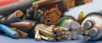
Types of cable
Cables from different brands, although they look similar, actually have a lot of differences. A variety of materials are used to produce cores and sheaths. In addition, products may have additional structural elements.
Depending on the metal from which the conductors are made, aluminum and copper conductors are distinguished.
Aluminum is an inexpensive material that is lightweight. However, the use of aluminum products as wiring in residential premises is prohibited, which is due to the disadvantages of the metal: fluidity; oxidation leading to the formation of an oxide film that impairs conductivity and brittleness.
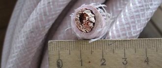
The electrical conductivity of copper conductors is 1.7 times better than that of aluminum conductors. The elasticity and flexibility of the material allows it to withstand many deformations during installation and use. However, copper is not ideal: the weight of a copper cable is three times that of its aluminum counterpart. The cost of the material is also not in its favor. In addition, the cores and contacts oxidize in air.
Moving from inside the conductor structure to the outside, let's look at insulating materials. The ability of cable and wire products to withstand various voltages, exposure to high and low temperatures, ultraviolet radiation, and resist mechanical damage and other external factors depends on their type. The most popular materials are polyvinyl chloride (PVC), polyethylene, rubber and impregnated paper.
Products in PVC insulation are laid indoors, which is due to the sensitivity of the material to low temperatures and ultraviolet radiation. Problems can be solved by the use of special additives, as well as installation in pipes. In general, the material resists damage and wear quite well.
Conductors in polyethylene sheaths, not subject to destruction by acids and alkalis, are operated over a wide temperature range. To improve characteristics, additives are used, as well as vulcanization. The technology allows better resistance to cracking and also increases the melting point.
The rubber-coated cable bends well and practically does not absorb moisture. The use of material increases the cost of the finished product. In addition, over time, the rubber shell loses its elasticity.
Conductors in impregnated paper based on kraft pulp can withstand voltages up to 35 kV. Additional shells are used to protect against moisture.
The cable design may contain additional elements. There are shielded, armored products, models in cotton and steel braid. Shielding is used to protect against interference and equalize the electromagnetic field inside conductors. Armoring protects cable and wire products from significant mechanical impacts. Braids help prevent insulation failure and also resist stretching.