How is the shunt connected to the Ammeter?
The shunt is connected in parallel to the ammeter to expand the scale of the device. When a shunt is connected, part of the current flows past the device through the shunt and thereby reduces the load on the device.
Interesting materials:
Which team did Demis Karibidis play for? Which monitor is better for IPS or TN gaming? What laptop do you need to play this? What kind of dog plays the dog in the movie? What is the maximum level in the game Hay Day? Which side to play ping pong? What is the best game accelerator for Android? What genre is the GTA game? What award did the winner receive at the Olympic Games? What role does the white matter of the spinal cord play?
Additional resistance. Scope, calculation.
Additional resistance is used to expand the measurement range of voltmeters.
A voltmeter is a device used to measure voltage at various points in a circuit. The rated voltage for which the voltmeter is designed is different for different devices. But sometimes a situation arises when a device designed to measure, say, millivolts, but we need to measure kilovolts. The main part of any voltmeter is its measuring head. This is some kind of electromechanical device that converts the current passing through it into the angle of deflection of the needle. In this case, the scale is graduated in measured values. In our case in volts. In digital measuring instruments, of course, this is not the case; there we see a digital display on which the results are displayed. But the method of expanding the range of the measuring part remains the same.
The angle of rotation of the arrow depends on the current flowing through the device. Since the resistance of the device is constant, the resulting angle of deflection depends on the voltage at the terminals of the device. These pins must be connected in parallel to the section of the circuit being measured. In this case, the voltmeter must have a sufficiently large internal resistance so as not to distort the operation of the circuit.
In practice, the resistance of the meter should differ by at least 100 times from the resistance of the circuit. Then the error introduced by the device will be only one percent. All measuring heads, as a rule, already have a high internal resistance. And since we decided to expand the measurement range by introducing an additional resistance, which is connected in series with the device, you don’t have to worry about the introduced error.
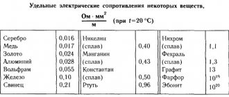
The additional resistance is made of a material that has a stable temperature coefficient of resistance. That is, when such a material is heated, its resistivity should not change. Otherwise, during measurements, due to the heating of such resistance when current passes through it or from the external environment, the error of the device will change.
As a rule, manganin is used as such a material, not to be confused with margarine. That is, now it is not the measuring head itself that is connected to a section of the circuit, but our voltmeter as a whole. Inside which this very head is connected in series with an additional resistor. Now you need to calculate the resistance of this resistor in order to know the value of the voltmeter division. To do this, you first need to determine the additional resistance multiplier.
The additional resistance multiplier is a ratio that shows how many times the voltage that is present at the voltmeter terminals is greater than the voltage supplied to the measuring head.
Well, knowing this multiplier it is easy to determine the amount of additional resistance
As a rule, portable measuring instruments are equipped with not one, but several additional resistances. Thus, they have some measurement ranges. This is done in order to increase the versatility of the voltmeter so that one device can measure voltage values in various circuits.
Source
Resistance
Additional resistances are voltage-to-current measuring converters that consist of 1 or more load elements. Additional resistance for a voltmeter is necessary when measuring voltages that exceed the maximum permissible measurement limit of a given measuring device. These elements are no different in functionality from ordinary resistors. When making measurements in high-voltage electrical circuits, both the addition and the device itself must be connected in series to the electrical circuit.
With a series connection, we find the amperage using the following formula:
- I is the measured current.
- U is the voltage of the electrical circuit.
- Ri is the resistance of the voltmeter.
- Rd - additional resistive resistance.
When it is necessary to increase the nominal operating mode of the device several times, this can be done using this simple calculation:
The formula for calculating the additional resistance itself is as follows:
Thanks to this expression, it can be determined that the value of the additional load will always be “n–1” greater than the measured value itself.
The above calculation of additional resistance allows us to significantly increase the nominal measurement limit, making them both direct and alternating voltages. For AC electrical circuits, resistive elements based on bifilar materials are used. Windings made of such materials are used to eliminate the influence of the reactive component.
What does the S2000-ASPT and S2000-KPB instruction manual say?
The S2000-ASPT operating manual does not say anything about additional resistances in the starting circuit; it contains the following :
The AUP launch control circuit is connected to the “P” terminals. The output parameters for connecting the AUP launch control circuit are given in Table 2.1. If the electric starting element of the AUP requires additional current limitation, then a limiting resistor must be connected in series with it. The calculated value of the limiting resistor Rolim is determined by the formula:
Iav required operation current, [A] Rwire – resistance of the wires between the S2000-ASPT unit and the AUP, [Ohm]; RAUP – average equivalent resistance of the squib (incandescent bridge), [Ohm]. Finally, the value of the current-limiting resistor is selected by the nearest lower value from the E24 series. The calculated value of the allocated power Wlim is determined by the formula:
Nothing is said about the case when all fire extinguishing modules are connected to the S2000-KPB slave (connected to the S2000-ASPT via RS485-2) and connection to the S2000-ASPT starting circuit is not required.
DURING COMMISSIONING WORK, AND ALSO IF ANY OF THE OUTPUTS IS NOT USED, A RESISTOR MUST BE CONNECTED TO ITS TERMINALS: 1.0 kOhm - 1 W.
But it is necessary to somehow roughen the starting circuit so that the device does not go into fault mode.
So you need to harden the unused S2000-ASPT launch output at least like this:
In this case, however, there will be an emergency to control the inrush current after start-up, and for complete simulation a current-limiting resistor is needed so as not to confuse the operating personnel at all.
The S2000-KPB operating manual contains the following connection diagram with additional resistors:
The installer is asked to calculate the resistance of the additional current-limiting resistor himself (well, it’s not for the designer to do this).
It is recommended to connect the AUP according to the diagram:
The length of the connecting wires used to connect the AUP and the resistance of the additional resistor must be such as to ensure the required operating current of the electric activator.
The value of the additional resistor Rd is calculated using the following formula:
, Where:
UIPmin – minimum voltage of the power supply (10 V for RIP-12 and 20 V for
I – required operation current, [A];
R1 – wire resistance between the power source and the unit, [Ohm];
R2 — wire resistance between S2000-KPB and AUP, [Ohm];
Raup – average equivalent resistance of the squib (incandescent bridge), [Ohm].
For example, when powered from a 24V source, the resistance of the connecting wires is less than 0.3 Ohm, the resistance of the squib is 6 Ohms and the calculated operating current of the squib is 0.1A, the resistance of the additional resistor is 160 Ohms. I don't know where to get it.
The MPN is an assembly of two diodes with protruding input and output wires.
The device is small and flat. The installers hide this MPN, along with the twists, behind the display board or in a corrugation.
If the designer designed fire-resistant distribution boxes “Hephaestus” and a cable with a cross-section of more than 1, then the matter is completely rubbish - there is nowhere to hide it all, not to mention the additional resistance.
Therefore, I believe that the topic of connecting fire extinguishing modules has not been worked through by manufacturers at all.
Why do you need additional resistance?
Very often the current or voltage in a circuit is much higher than the permissible value that a measuring device (voltmeter, ammeter or other) can measure.
In such cases, such parameters can be measured by adding special additional elements to the electrical circuit. The article will give a detailed explanation of what additional resistance is and why it is needed. A description and purpose of shunt devices will also be given, as well as the formulas used to calculate the parameters of such elements.
Connecting fire extinguishing modules to Signal-20M.
There is, of course, an interesting possibility, described in the article Fire extinguishing based on S2000M and S2000-KDL.
Launching the outputs of the Signal-20M device is no different from launching the outputs of the S2000-SP2 ISP2 addressable devices and the S2000-KPB interface devices under the control of the S2000M (not to be confused with connecting the S2000-KPB as a slave to the S2000 -ASPT").
But this is a slippery slope and I consider it here as an example.
The new Signal-20M device has as many as 4 outputs that allow you to connect fire extinguishing modules.
Connection diagram for the actuator of the AUP launch circuit:
The circuit allows you to connect one actuator of the AUP launch circuit to the output of the device: a squib, a locking device or another device that has low resistance (units... tens of Ohms). Elements for monitoring the health of the line (4.7 kOhm resistor and diode type 1N5400 or similar) should be placed in the housing of the actuator or in the mounting compartment of the device. The circuit provides monitoring of the health of the device and communication line both in the on and off state. In the off state, the presence of a terminal element (4.7 kOhm resistor) is monitored using a small current of reverse polarity. In the on state, the health of the communication line and the actuator is monitored by monitoring the current consumption of the output circuit (straight polarity).
No additional resistance is provided.
How to connect fire extinguishing modules in the Bolide fire extinguishing system?
I think that it is best to always use a slave “S2000-KPB” (this is not difficult, since one starting device is rarely used) and connect fire extinguishing modules to the outputs of the “S2000-KPB” without current-limiting resistors, since the “S2000-KPB” protects its outputs.
In order to distribute in time the moments when fire extinguishing modules are activated, when setting up in pprog, it is necessary to specify the offset time between output launches and the duration of the trigger pulse. For example, 7 sec and 4 sec. Then the fire extinguishing modules will be launched one by one. This will allow the power channel to be used only to launch one fire extinguishing module at any given time.
For greater reliability, when using several S2000-KPBs, you can distribute power among them using a special safe power switching device.
Source