Online electrical magazine. Starting and running winding resistance
The starting (auxiliary) winding is designed to create the necessary starting torque.
According to the method of creating starting torque, single-phase electric motors can be divided into motors with a running capacitor (the capacitor is permanently connected to the starting winding) and motors with a starting capacitor (the capacitor is connected to the auxiliary winding during the start). In terms of their design, the main and starting windings have a number of differences. First of all, this is the cross-section of current-carrying conductors. The cross-section of the wires of the working winding is larger due to the long stay of the winding under load. It is this condition that is used to determine the starting and operating windings of the electric motor. The working winding has a larger conductor cross-section, and therefore less active resistance.
The terminal box of a single-phase electric motor has 3 or 4 terminals. To determine the starting and operating windings, it is necessary to measure the active resistance of the conductors. Sometimes the windings can be distinguished visually, knowing that the working one has a larger cross-section. The working winding is connected to the AC mains. One of the starting terminals is to the output of the working winding, the second is through a capacitor to the other end of the working winding. The direction of rotation of the motor is determined by the connection of the starting winding and does not depend on the polarity of the supply voltage.
For electric motors with 3 terminals, it is also necessary to measure active resistances. A combination of resistances of 10 Ohm, 25 Ohm and 15 Ohm is quite common. In this case, one of the terminals of the main winding will have the lowest resistance (10 Ohms), and the second, when measured with the other two terminals, will show 10 Ohms and 15 Ohms. The third pin will be the start winding pin. The direction of rotation of such a motor can be changed only by changing the winding connection diagram, for which it is necessary to disassemble the electric motor.
Total
Checking the motor windings. Malfunctions and test methods
Ideally, in order to check the windings of an electric motor, it is necessary to have special instruments designed for this, which cost a lot of money. Surely not everyone has them in their home. Therefore, it is easier for such purposes to learn how to use a tester, which has another name: a multimeter. Almost every self-respecting home owner has such a device.
Electric motors are manufactured in various versions and modifications, and their malfunctions are also very different. Of course, not every fault can be diagnosed with a simple multimeter, but most often checking the motor windings with such a simple device is quite possible.
Any type of repair always begins with an inspection of the device: the presence of moisture, whether parts are broken, the presence of a burning smell from the insulation and other obvious signs of malfunction. Most often, the burnt winding is visible. Then no checks and measurements are needed. Such equipment is immediately sent for repair. But there are times when there are no external signs of failure, and a thorough check of the motor windings is required.
Connection diagrams for single-phase asynchronous motors
With starting winding
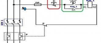
To connect a motor with a starting winding, you will need a button in which one of the contacts opens after switching on. These opening contacts will need to be connected to the starting winding. In stores there is such a button - this is PNDS. Its middle contact closes for the holding time, and the two outer ones remain in a closed state.
Appearance of the PNVS button and the state of the contacts after the “start” button is released"
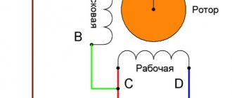
First, using measurements, we determine which winding is working and which is starting. Typically the output from the motor has three or four wires.
Consider the option with three wires. In this case, the two windings are already combined, that is, one of the wires is common. We take a tester and measure the resistance between all three pairs. The working one has the lowest resistance, the average value is the starting winding, and the highest is the common output (the resistance of two windings connected in series is measured).
If there are four pins, they ring in pairs. Find two pairs. The one with less resistance is the working one, the one with more resistance is the starting one. After this, we connect one wire from the starting and working windings, and bring out the common wire. A total of three wires remain (as in the first option):
- one from the working winding is working;
- from the starting winding;
- general.
We work further with these three wires - we use them to connect a single-phase motor.
With all these
- Connecting a single-phase motor with a starting winding via the PNVS button
connecting a single-phase motor
We connect all three wires to the button. It also has three contacts. Be sure to place the starting wire on the middle contact (which closes only during the start), the other two - on the outermost (arbitrary). We connect a power cable (from 220 V) to the extreme input contacts of the PVNS, connect the middle contact with a jumper to the working one (note! not to the common one). That's the whole circuit for switching on a single-phase motor with a starting winding (bifilar) through a button.
Condenser
When connecting a single-phase capacitor motor, there are options: there are three connection diagrams and all with capacitors. Without them, the engine hums, but does not start (if you connect it according to the diagram described above).
Connection diagrams for a single-phase capacitor motor
The first circuit - with a capacitor in the power supply circuit of the starting winding - starts well, but during operation the power it produces is far from rated, but much lower. The connection circuit with a capacitor in the connection circuit of the working winding gives the opposite effect: not very good performance at start-up, but good performance. Accordingly, the first circuit is used in devices with heavy starting (concrete mixers, for example), and with a working condenser - if good performance characteristics are needed.
Circuit with two capacitors
There is a third option for connecting a single-phase motor (asynchronous) - install both capacitors. It turns out something between the options described above. This scheme is implemented most often. It is in the picture above in the middle or in the photo below in more detail. When organizing this circuit, you also need a PNVS type button, which will connect the capacitor only during the start time, until the motor “accelerates”. Then two windings will remain connected, with the auxiliary winding through a capacitor.
Connecting a single-phase motor: circuit with two capacitors - working and starting
When implementing other circuits - with one capacitor - you will need a regular button, machine or toggle switch. Everything connects there simply.
Selection of capacitors
There is a rather complex formula by which you can calculate the required capacity accurately, but it is quite possible to get by with recommendations that are derived from many experiments:
- The working capacitor is taken at the rate of 70-80 uF per 1 kW of engine power;
- starting - 2-3 times more.
The operating voltage of these capacitors should be 1.5 times higher than the network voltage, that is, for a 220 volt network we take capacitors with an operating voltage of 330 V and higher. To make starting easier, look for a special capacitor for the starting circuit. They have the words Start or Starting in their markings, but you can also use regular ones.
How to check an electric motor armature: 4 types of different designs
The rotor windings create a magnetic field, which is influenced by the stator field. They must also be in good working order. Otherwise, the energy of the rotating magnetic field will be wasted.
Armature windings have different designs for wound-rotor, asynchronous and commutator motors. This is worth considering.
Synchronous wound rotor models
At the anchor, wire leads are created in the form of metal rings located on one side of the shaft near the rolling bearing.
The wires of the circuit are already assembled to these rings, which causes small differences in checking them with a multimeter. You should not turn them off, however, the technique described above for the stator is, in principle, suitable for this design.
Such a rotor can also be conditionally represented as a working transformer. All you need to do is compare the individual resistances of their circuits and the quality of insulation between them, as well as the housing.
Asynchronous motor armature
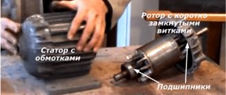
In most cases, the situation here is much simpler, although there may be problems. The fact is that such a rotor is made in the shape of a “squirrel wheel” and is difficult to damage: a fairly reliable design.
The short-circuited windings are made of thick aluminum rods (rarely copper) and are firmly pressed into the same bushings. All this is designed for the flow of short circuit currents.
However, in practice, various damages occur even in reliable devices, and somehow they need to be found and eliminated.
A digital multimeter is not required to identify faults in the squirrel wheel winding. Here you need other equipment that supplies voltage to the short circuit of this armature and controls the magnetic field around it.
However, internal failures of such structures are usually accompanied by cracks on the body, and they can be noticed during a careful internal inspection.
Who is interested in such testing using electrical methods, watch the video of the owner Viktor Yungblyudt. He shows in detail how to determine the breakage of the rods of such a rotor, which makes it possible to subsequently restore the functionality of the entire structure.
Commutator motors: 3 winding analysis methods
The electrical circuit diagram of a commutator motor in a simplified form can be represented by rotor and stator windings connected through a brush mechanism.
The diagram of an assembled electric motor with a commutator mechanism and brushes is shown in the following picture.
The rotor winding consists of parts connected in series with each other by a certain number of turns on the collector plates. They are all of the same design and therefore have equal active resistance.
This allows you to check their serviceability with a multimeter in ohmmeter mode using three different methods.
The simplest measurement method
I show principle No. 1 of determining the resistance between the collector plates in the photo below.
Here I made one simplification that cannot be made in a real test: I was too lazy to remove the brushes from the brush holder, and they create additional chains that can distort the information. Always take them out for accurate measurements.
The probes are placed on adjacent lamellas. This type of measurement requires precision and perseverance. You must mark the collector with paint or a felt-tip pen. From there you will have to move in a circle, taking sequential measurements between all successive plates.
Constantly monitor the device readings. They should all be the same. However, the resistance of such sections is small and if the ohmmeter does not respond to it accurately enough, then it can be sensed by increasing the length of the chain being measured.
Method No. 2: diametric measurement
This second method will require even greater care and concentration. The ohmmeter probes must be placed not on the nearest adjacent plates, but on diametrically opposite ones.
In other words, the multimeter probes should fall on those plates that are connected by brushes when the electric motor is running. And to do this, they will need to be marked somehow so as not to get confused.
However, even in this case there may be difficulties associated with measurement accuracy. Then you will have to use the third method.
Method No. 3: indirect method of comparing small resistance values
To measure, we need to assemble a circuit that includes:
It should be imagined that the measurement accuracy increases the stability of the created current source due to:
One connecting wire is connected directly to the battery terminal and the collector lamella, and a current-limiting resistor is inserted into the second, eliminating large currents. A voltmeter is placed parallel to the contact plates.
The next pairs of lamellas on the collector are sequentially moved with probes and readings are taken with a voltmeter.
Since the battery and resistor produce the same voltage for a short time of each measurement, the voltmeter readings will depend only on the resistance value of the chain connected to its terminals.
Therefore, with equal readings, we can conclude that there are no defects in the electrical circuit.
If desired, you can measure the current through the lamellas with a milliammeter and, using Ohm's law, use an online calculator to calculate the value of active resistance.
My digital Mestek MT102, despite the shortcomings identified in it, copes well with this task.
DC motors
The design of their rotor is reminiscent of the armature device of a commutator motor, and the stator windings are created to work with a switching circuit with parallel, series or mixed excitation.
The stator and armature testing methods disclosed above allow you to check a DC motor, both asynchronous and commutator.
Distinguishing types of single-phase motors in practice
Let's learn how to distinguish a bifilar motor from a capacitor motor. It should be said that the difference is purely nominal. The connection diagram for a single-phase motor is similar. The bifilar winding is not designed to operate continuously. It will interfere and reduce efficiency. Therefore, it is interrupted after a set of revolutions by a start-up relay (inherent in household refrigerators) or by centrifugal switches. It is believed that the starting winding operates for several seconds. According to generally accepted standards, it will launch 30 times per hour, lasting 3 seconds each. Then the coils may overheat (burn out). The reason that limits the starting winding being energized.
The difference is nominal, but professionals note an interesting feature by which they judge whether we have a bifilar or capacitor motor. Auxiliary winding resistance. The nominal value differs from the working one by more than 2 times, most likely the engine is bifilar. Accordingly, the winding is starting. A capacitor motor operates using the services of two coils. Both are constantly under tension.
Single phase asynchronous motor
The test must be carried out carefully; in the absence of thermal fuses and other means of protection, the starting winding may burn out. You will have to unscrew the shaft manually, which is clearly not an easy task. Sometimes it is advisable to connect a single-phase asynchronous motor to a single-phase network using a similar circuit, as was done in previous equipment. An ordinary refrigerator is equipped with a start-up relay, a separate topic of discussion. The parameters of the device are closely related to the type of engine used; mutual replacement is not possible in every case (violation of a simple rule can cause breakdown).
Let us mention it twice: there can be three or four winding terminals. The number is not informative. A pair of thermal fuse contacts is acceptable. Plus the above, including the centrifugal switch. In the case of continuity, the resistance is either low, or vice versa - we fix the gap. By the way, do not forget to test each end of the coil against the body when determining the resistance. Insulation is standard not lower than 20 MOhm. Otherwise, you should think about the presence of a breakdown. We also assume that a three-phase motor with internal star-type winding commutation may have a neutral output to the housing. In this case, the motor requires an indispensable grounding, for which a terminal is provided (but it is more likely that the motor simply failed due to an insulation breakdown).
Electric motor device
Single-phase 220 V motors have two phases, but the main work is done by one, and such motors began to be called single-phase. The motor consists of the following parts.
- The stator, or stationary part of the motor.
- The rotor, or the moving (rotating) part of the motor.
A single-phase electric motor can be characterized as an asynchronous electric motor, which has a working winding on its stationary part, which is connected to a single-phase alternating current network.
Trigger coil
In order for a single-phase motor to start and rotate independently, another coil is installed on them. It is designed to start the engine. The starting coil is installed in relation to the working coil with an offset of 90 degrees. In order to obtain a current shift, you should install a link in the circuit that will shift the phases. Several means can act as a phase-shifting link.
- Active resistor.
- Capacitor.
- Inductor.
The rotor and stator of the motor are metal. In order to make a rotor or stator, you need special electrical steel grade 2212.
Two and three phase motors
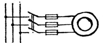
It is possible to connect a 2 or 3-phase motor to a single-phase power source.
Sometimes, by mistake, such motors are called single-phase. This is a misconception; it would be correct to call it “a two (or three) phase electric motor connected to a single-phase AC power supply.” Simply connecting a two or three-phase motor to a single-phase network will not work. We need a coordination scheme. There are several such circuits; matching can be achieved using capacitors. After connecting capacitors to the motor according to the diagram, the motor will work, and all phases of the motor will work, they will always be energized and perform work to rotate the rotor.
Operating principle
An alternating electric current creates a magnetic field in the stator, which has two fields, they are identical in amplitude and frequency, but in different directions. These fields act on a stationary rotor, and, due to the fact that the fields are multidirectional, the rotor begins to rotate. If there is no trigger mechanism in the motor, the rotor will stand still. The rotor, having begun to rotate in one direction, will continue to rotate in the same direction.
Starting the engine
The motor is started by means of a magnetic field; the magnetic field, acting on the rotor, forces it to rotate.
The main and additional coils create a magnetic field; the starting coil is smaller; it is connected to the additional coil through a capacitor, inductor or active resistor. If the motor is low power, the starting phase is closed. To start such an engine, you can connect electricity to the starting coil only temporarily, for no more than three seconds. There is a start button for this. The button is inserted into the trigger.
When the start button is pressed, electricity is supplied to the working and starting coils simultaneously, the engine in these first seconds of startup operates as a two-phase one, but after three seconds the rotor has already picked up speed, the motor starts, and the button is released. The supply of electricity to the starting coil stops, but the supply of electricity to the working winding does not stop, this is how the starting device is designed, then the device operates as a single-phase one.
It is important to remember that you should not hold the trigger button for long, as the trigger coil may overheat and fail; it is designed to operate for a few seconds. To ensure safety, a thermal relay and a centrifugal switch can be built into the housing of a single-phase power unit. The centrifugal switch is designed in such a way that when the rotor picks up speed, the centrifugal switch turns off itself, without human intervention. The starting current of a single-phase motor is higher than the operating one; after starting, the current decreases to the operating level. See the connection diagram for a single-phase motor here.
Types of windings
If you don’t go into details, the motor winding can be imagined as a piece of conductor that is wound in a certain way in the motor housing, and it seems that nothing should break in it.
However, the situation is much more complicated, since the electric motor winding has its own characteristics:
If there is any violation of these requirements, then the electric current will flow under completely different conditions, and the electric motor will deteriorate its performance, that is, the power, speed will decrease, and may not work at all.
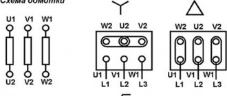
The ends of these windings are usually connected to blocks with terminals that have the appropriate markings: “K” - end, “N” - beginning. There are options for internal connections, the nodes are located inside the motor housing, and different markings (numbers) are used on the terminals.
The stator of a 3-phase electric motor uses windings that have equal characteristics and properties, and the same resistance. When measuring the winding resistances with a multimeter, it may turn out that they have different values. This already makes it possible to assume that there is a malfunction in the electric motor.
Possible faults
It is not always possible to visually determine the condition of the windings, since access to them is limited by the design features of the engine. In practice, you can check the winding of an electric motor using its electrical characteristics, since all motor breakdowns are mainly detected:
Methods
Checking the motor windings for open circuits
This is the simplest type of verification. The malfunction is diagnosed by simply measuring the wire resistance value. If the multimeter shows very high resistance, then this means that there is a wire break with the formation of air space.
Checking the motor windings for short circuits
If there is a short circuit in the motor, its power will be cut off by the installed short circuit protection. This happens in a very short time. However, even in such a short period of time, a visible defect in the winding may occur in the form of carbon deposits and metal melting.
If you measure the winding resistance with instruments, you get a small value that approaches zero, since a piece of the winding is excluded from the measurement due to a short circuit.
Checking the motor windings for interturn short circuits
This is the most difficult task in identifying and troubleshooting. To check the motor winding, several measurement and diagnostic methods are used.
Checking the motor windings using an ohmmeter
This device operates on direct current and measures active resistance. During operation, the winding forms, in addition to active resistance, a significant inductive resistance value.
If one turn is closed, then the active resistance will practically not change, and it is difficult to determine it with an ohmmeter. Of course, you can accurately calibrate the device, carefully measure all windings for resistance, and compare them. However, even in this case it is very difficult to detect shorted turns.
The results are much more accurately produced by the bridge method, which measures active resistance. This method is used in a laboratory environment, so ordinary electricians do not use it.
Current measurement in each phase
The phase current ratio will change; if a short circuit occurs between the turns, the stator will heat up. If the engine is fully operational, then the current consumption is the same in all phases. Therefore, by measuring these currents under load, we can confidently say about the actual technical condition of the electric motor.
Checking motor windings with alternating current
It is not always possible to measure the total winding resistance and take into account the inductive reactance. For a faulty motor, you can check the winding with alternating current. For this, an ammeter, a voltmeter and a step-down transformer are used. To limit the current, a resistor or rheostat is inserted into the circuit.
To check the motor winding, a low voltage is applied and the current value is checked, which should not be higher than the nominal value. The measured voltage drop across the winding is divided by the current to obtain the total resistance. Its value is compared with other windings.
The same circuit makes it possible to determine the current-voltage properties of the windings. To do this, you need to take measurements at various current values, then write them down in a table or draw a graph. There should not be large deviations when comparing with other windings. Otherwise, there is an interturn short circuit.
Checking the motor windings with a ball
This method is based on the formation of an electromagnetic field with a rotating effect if the windings are in good condition. They are connected to a symmetrical voltage with three phases, low value. For such tests, three step-down transformers with the same data are used. They are connected separately for each phase.
To limit the load, the experiment is carried out in a short period of time.
Voltage is applied to the stator windings, and a small steel ball is immediately introduced into the magnetic field. When the windings are in good condition, the ball rotates synchronously inside the magnetic circuit.
If there is a short circuit between the turns in any winding, the ball will immediately stop where there is a short circuit. When carrying out the test, the current must not be allowed to exceed the rated value, since the ball can fly out of the stator at high speed, which is dangerous for humans.
Determining the polarity of windings using the electrical method
The stator windings have terminal markings, which sometimes may not be there for various reasons. This creates difficulties during assembly.
To determine the marking, several methods are used:
The stator acts as a magnetic circuit with windings operating on the principle of a transformer.
Determining the marking of winding terminals with an ammeter and battery
On the outer surface of the stator there are six wires from three windings, the ends of which are not marked and must be determined by their affiliation.
Using an ohmmeter, find the terminals for each winding and mark them with numbers. Next, mark one of the end and beginning windings, randomly. A dial ammeter is connected to one of the remaining two windings so that the arrow is in the middle of the scale to determine the direction of the current.
The negative terminal of the battery is connected to the end of the selected winding, and the positive terminal briefly touches its beginning.
The pulse in the first winding is transformed into a second circuit, which is closed by an ammeter, and repeats the original shape. If the polarity of the windings coincides with the correct location, then the arrow of the device at the beginning of the pulse will go to the right, and when the circuit opens, the arrow will move to the left.
If the instrument readings are completely different, then the polarity of the winding terminals is reversed and marked. The remaining windings are checked in a similar way.
Determining polarity with a voltmeter and a step-down transformer
The first stage is similar to the previous method: they determine whether the terminals belong to the windings.
Next, the terminals of the first winding are randomly marked to connect them to a step-down transformer (12 volts).
The other two windings are connected randomly with two terminals at one point, the remaining pair is connected to a voltmeter and the power is turned on. The output voltage is transformed into other windings with the same value, since they have the same number of turns.
Using a series connection circuit, the 2nd and 3rd windings of the voltage vector are summed up, and the result is shown by a voltmeter. Next, the remaining ends of the windings are marked and control measurements are carried out.
Source
How to decide on engine type
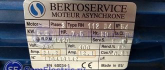
If the engine is new, then there will be no special problems, since its nameplate indicates the engine type and other data. If the engine has been repaired, then determining its type is associated with some difficulties: the plate could simply be lost or damaged mechanically. Therefore, in such cases, it is better to know how to independently determine the type of engine.
Brushed motors
Determining whether a motor is commutator or asynchronous is not at all difficult, since they have different structures. A characteristic difference between a commutator motor is the presence of brushes that are stationary, as well as a commutator that rotates and consists of a set of copper plates. Brushes are pressed against these plates, transmitting electric current to the motor armature winding.
The advantage of such engines is that they accelerate quickly and allow you to get high speeds. In addition, by changing the polarity, it is possible to change the direction of rotation of the device. No less important can be considered the factor that you can easily organize control of the engine speed, with its adjustment within a wide range.
A significant disadvantage of commutator engines is their increased noise during operation, especially at high speeds. As for low speeds, the performance of these engines can be considered quite acceptable. It should also be taken into account that the friction of the brushes and commutator leads to wear of both the brushes and the commutator. As a result, you have to change the brushes or grind the commutator. If you do not constantly monitor the condition of the brushes and commutator, there is a high probability that the device will have to be repaired.
Asynchronous motors
The design of an asynchronous motor is somewhat different from the design of a commutator motor, despite the fact that it also has a stator and a rotor (armature), while asynchronous motors can be either single-phase or three-phase. As a rule, household electrical appliances are equipped with single-phase asynchronous motors.
The advantage of asynchronous motors is that they are quieter, so they are installed in household appliances whose operation is associated with critical noise levels during long-term operation.
There are two types of asynchronous motors - capacitor and with a starting winding (bifilar). The starting winding is needed only to start the engine, after which it turns off and does not take any part in the operation of the engine.
Capacitor motors are distinguished by the fact that the additional capacitor winding operates continuously. This winding is shifted relative to the working winding by 90 degrees. Thanks to this construction, it is possible to change the direction of rotation of the engine. The presence of a capacitor on the motor indicates that it is a capacitor motor.
If you measure the resistance of the starting and operating windings, you can easily determine the type of asynchronous motor. As a rule, the starting winding is made of thinner wire and its resistance is several times greater than the working winding. The normal operation of such engines is ensured by a special switching device. Capacitor motors are started by a regular switch, toggle switch or button.
Principle of operation
The operating principle of a single-phase asynchronous electric motor is to create a pulsating magnetic flux from the flow of electric current through the main stator winding, if we consider the option of starting from an auxiliary turn. Thus, we will consider connecting a single-phase motor to the network using the example of one turn.
From a physical point of view, both flows are equivalent, so changing them at intervals of 100 times per second will give a zero result when added. The forward magnetic flux will be equal to the reverse one:
This means that if the rotor of an electric motor is in such a field, it will not rotate. The magnetic flux will change 100 times a minute, and the squirrel-cage rotor will simply hum, remaining in place. However, the situation will change radically if there is an impulse to the initial movement. In this case, slipping will appear, which will lead to constant rotation of the shaft:
- n1 – rotation frequency of the magnetic field of a single-phase electric motor;
- n2 – rotor speed of the asynchronous electric motor;
- S is the slip value of a single-phase induction motor.
When the magnetic flux changes, the direction of rotation and the fields of the stator and rotor of the electric motor will coincide, so the slip will receive a different expression for calculation:
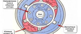
The alternating intersection of the rods with magnetic fluxes of different directions will create an EMF in them, which will generate an electric current in the rotor and a response magnetic flux. And it, in turn, will also interact with the stator field of a single-phase electric motor, as shown in the figure below.
What kind of lighting do you prefer?
Built-in Chandelier
As you can see, to connect a three-phase electric motor, you just need to apply voltage to it, but this option will not work with a single-phase one.
To start the motor, a primary impulse is required, which in practice can be obtained by:
Of the above methods, today the first is used only in laboratory experiments; it has fallen out of practical use due to the risk of injury to the operator.
How to distinguish on a single-phase motor
Single-phase motors are equipped with two types of winding so that their rotor can rotate, since only one is not enough for this. Therefore, before connecting the motor, you need to figure out which skein is the main one and which is the auxiliary one. There are several ways to do this.
By color coding
What type a particular skein is can be determined by color markings during a visual inspection of the engine. As a rule, red wires are of the working type, but blue wires are of the auxiliary type.
But all rules have their exceptions, so it is always necessary to pay attention to the electric motor tag, on which a decoding of all markings is applied.
However, if the engine has already been repaired or there is no tag on it, this method of checking is not effective. In the first case, during repair work, the internal contents of the motor could completely change, and in the second, there is no way to accurately decipher the color symbols. In addition, sometimes there may be no markings at all. Therefore, in such situations, it is better to resort to another, more reliable method.
By wire thickness
The thickness of the wires that come out of a low-power electric machine will help distinguish the starting coil from the working one. Since the auxiliary one works for a short time and does not experience serious load, the wires related to it will be thinner.
However, it is not always possible to determine the thickness of the wire cross-section with the naked eye; sometimes the difference between them is completely invisible to humans.
But even if it catches your eye, you shouldn’t rely on that alone. Therefore, many always measure the resistance of wires.