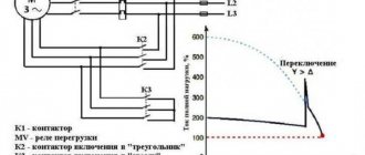
Starting current and its multiplicity
To move (start) the engine, you need a huge starting current (Ip). Enormous - compared to the rated (operating) current In at steady speed. Articles usually indicate that the starting current exceeds the operating current by 5-8 times. This number is called “Starting current multiplicity” and is designated as coefficient Kp = Ip / In.
Starting current is the current that the electric motor consumes during starting. You can find out the starting current by knowing the rated current and the Kp coefficient:
Iп = Кп · In
The rated current is always indicated on the motor nameplate:
Rated motor current for different voltages and circuits
Gearbox is an operating parameter that is indicated in the engine characteristics, but it is never indicated on the engine body.
I note that there is no need to confuse rated and operating currents. The rated current is the current at which the motor can operate for a long time; it is limited only by heating the stator winding. The operating current is the real current in a given unit; it is always less than or equal to the rated one. In practice, operating current is measured using a clamp meter, ammeter or current transformer.
If the operating current is greater than the rated current, expect trouble. Read my article about how to protect an electric motor from overload and overheating.
Multiplicity of starting current. It is usually not on the nameplate, but it is present in the documentation and on manufacturers’ websites:
Engine parameters. Starting current ratio
Example from the first line in the picture: a specific 1.5 kW motor has a rated current of 3.4 A. This means that the starting current at some point (how long this “moment” lasts - we’ll look at it below) can reach a value of 3.4 x 6 .5 = 22.1 A!
Judging by the catalogs (they can be downloaded at the end of the article, as usual with me), the starting current exceeds the rated current in the range from 3.5 to 8.5 times.
The starting current multiplicity depends primarily on the engine power and the number of pole pairs. The lower the power, the lower the starting current. And the fewer pairs of poles (the higher the rated speed), the greater the starting current.
That is, high-speed motors (3000 rpm, 1 pair of poles) of relatively high power (more than 10 kW) have the highest starting current (7 - 8.5 of the nominal value).
This happens because the current consumption and moment of inertia at start-up depend on the design of the motor and the winding method. Few poles - low winding resistance. Low resistance - high current. In addition, high-speed engines require more time to fully rev up, and this is again a difficult start.
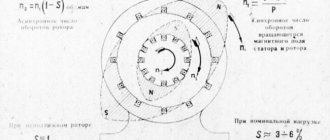
To explain it in more scientific language, it goes like this. When the engine is stationary, its slip degree S = 1. When spinning up (or, as experts like to say, unwinding), S tends to zero, but never reaches it - that’s why the motor is called asynchronous, because the rotation of the rotor will never catch up with the rotation of the stator field due to losses. At the same time, the rotor core is saturated with a magnetic field, the self-induction emf and inductive resistance increase. This means the current decreases.
For those who want to know more, at the end of the article I have posted several good books on the topic.
In fact, it’s not that simple, let’s start digging deeper.
Motor current calculation
Hello visitors to the site fazanet.ru, and in today’s article we will figure out how to do this incomprehensible calculation of the electric motor current.
Every self-respecting electrician whose work involves servicing electrical machines simply must know this. I also remember at one time that I was very interested in this when I was transferred from one workshop to another. Specifically, working as an electrician. Before this, I already touched a little on the topic of electric motors, when I wrote about how to start asynchronous motors, and when I wrote what the ratings of electric motors are.
Well, now let's get down to the calculation itself. Let's say: you have a three-phase asynchronous AC electric motor, the rated power of which is 25 kW, and you want to know what its rated current will be.
There is a special formula for this: In = 1000Pн /√3•(ηн • Un · cosφн),
Where Pн is the power of the electric motor; measured in kW
Un is the voltage at which the electric motor operates; IN
ηн is the efficiency factor, usually this value is 0.9
Well, cosφн is the engine power factor, usually 0.8.
The last two values are usually written on the factory tag, although they are almost the same for all engines. But you still need to take the data from the factory tag on the engine.
This is how in this picture all the values are visible, but the current is not. Only if the efficiency is written as 81%, then for the calculation you need to take 0.81.
Now let’s substitute the values In = 1000•25/√3 • (0.9 • 380 • 0.8) = 52.81 A
For those who don’t remember how much √3 will be, let me remind you – it will be 1.732
That's it, all calculations are completed. Everything is very easy and simple. Using my example, you can easily calculate the rated current of the electric motor, you just need to substitute your data.
How to find out the starting current?
The starting current multiplicity (the ratio of the starting current to the rated current) is not so easy to find in the engine documentation. But you can measure (evaluate, find out) yourself. Here are a few ways off the top of your head:
- The first way (the best for theoretical study) is to use an oscilloscope. Take a shunt (for example, a 0.1...0.5 Ohm resistor, the smaller compared to the windings, the better), and look at the oscillogram on it at the time of start-up. Next, from the maximum amplitude value, we determine the effective voltage (divide by the root of 2), then, according to Ohm’s law, we calculate the starting current. You don’t have to multiply or divide anything - just measure the current with clamps in operating mode, and multiply it by the difference in currents on the oscilloscope screen. The good thing about this method is that you can see transient processes caused by self-induction emf, instantaneous current values, and acceleration duration. In addition, the parameters of the supply network are taken into account. Another plus is that the starting current is measured real, on a real engine and mechanism.
- The second way to measure the starting current is to apply a reduced (5-10 times) operating frequency voltage to the motor and measure the current. Why reduced? This is necessary so that the rotor can be easily fixed without overheating. Recalculate the measured current to obtain the starting current. It is enough to measure the current in one phase. For others, the currents will be (must be) the same. This method is used in the production and testing of engines. It is in this way that manufacturers obtain tabular data. The method is based on the rated current; in reality (on a real mechanism) the starting current may be different!
- Measure the starting current with a clamp meter. The advantage of this method is simplicity and efficiency. Pincers are used in most cases to check engine operating conditions. The downside is that such pincers are quite inertial, and we need to see what is happening in a split second. But this minus is leveled out when we measure the current when starting a load with a high moment of inertia (fans, pumps with massive impellers). The start-up lasts more than 10 seconds, and everything is visible on the ticker screen. I will add that there are clamps with the Inrush function that can measure the inrush current from 0 to maximum during an integration time of about 100 ms.
- Current transformer. This is used, for example, in electricity metering units - thanks to the current transformer, there is no need to measure the real current, but you can measure the current reduced by a precisely known number of times. They also measure current in electronic starting devices (frequency converters, soft starters). The disadvantage of this method is that the current transformer is designed for a frequency of 50/60 Hz, and transient processes during startup have a wide spectrum and many harmonics. Therefore, we can say that this method also has high inertia.
Of course, reality is different from experiment. First of all, the short circuit current of a real power supply network is not infinite. That is, the wires supplying the engine have a resistance at which the voltage drops at the moment of starting (sometimes by up to 50%). Because of this limitation, the actual starting current will be less and acceleration will take longer. Therefore, you need to understand that the value of the starting current multiplier specified by the manufacturer will always be less in reality.
What are engines for - to power machinery and make a profit!
Now let's look at another question -
Valve motors
The group of valve electric motors includes drives in which the operating mode is controlled by means of valve converters.
The advantages of this equipment include:
- High service life.
- Easy maintenance due to contactless control.
- High overload capacity, which is five times the starting torque.
- Wide speed control range, which is almost twice the range of asynchronous electric motors.
- High efficiency at any load - more than 90 percent.
- Small dimensions.
- Fast payback.
What is the harm from inrush current?
Inrush current is a problem. This -
- overload of the supply network, leading to heating (up to the contacts burning out) and voltage sags;
- excessive wear, overload and overheating of the engine; some manufacturers indicate among the engine parameters the maximum number of starts per hour or per day - precisely because of overheating;
- wear and overload of the mechanical drive (bearings, gearboxes, belts), especially those with a large moment of inertia,
- interference caused by the activation of contactors, which are transmitted not only through wires, but also through an electromagnetic field,
- problems with technology - many processes cannot be started abruptly.
The starting current overloads everything, and the moment of starting becomes a burden to all participants in the process. It is at this critical moment that a “weak link” may appear. In addition, many power participants operating on this network experience problems - for example, light bulbs dim due to low voltage, and controllers can freeze due to strong interference.
And at the same time, starting current is a problem that cannot be avoided if you immediately supply the motor with rated power and do not use special methods.
So let's figure it out
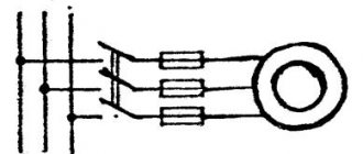
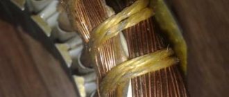
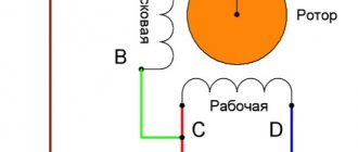
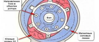
The principle of operation of an electric motor with a wound rotor
Now let's take a closer look at the principle of operation of an asynchronous motor with a phase rotor and its connection. Here we can distinguish a sequence of five important stages:
- the first stage - the stator, which has a triple winding, receives voltage from a three-phase AC power supply with the required parameters;
- second stage – a magnetic field is formed, driving the rotor;
- third stage - the rotor gradually accelerates, and its speed increases significantly;
- fourth stage - when the stator and rotor field lines reach a certain value and intersect, an electromotive force arises, acting on the rotor winding and creating an electric current on it;
- fifth stage - the stator and rotor magnetic fields begin to actively interact with each other, maintaining the torque of the shaft.
Next, the asynchronous motor with a phase-type rotor is controlled in normal mode. The operating principle of an asynchronous motor with a wound rotor differs from the squirrel-cage version by the presence of a full three-phase winding with a similar arrangement on the stator and rotor parts.
A typical control circuit for an asynchronous motor with a wound rotor looks like this:
The control diagram of an asynchronous motor with a wound rotor shows that the rotor winding leads are connected to slip rings mounted on the electric motor shaft. These rings have protective insulation, both among themselves and at the points of contact with the shaft. For each of the phases, of which there are usually three, the rotor has its own separate winding. The starting circuit for these windings most often has the form of a “Star”.
A control rheostat is mounted to the rotor winding, coupled with brushes and slip rings. Despite the apparent complexity of such a design and a more careful calculation of an asynchronous motor, the possibilities for adjusting the operating torque on the shaft are an order of magnitude greater than for motors with a squirrel-cage rotor, the control and use of which is usually associated with the need to use a frequency converter or a special speed controller.
The stator winding is created taking into account the number of coils and poles, of which there should be the same number on the stator and rotor. The stator coils shift between each other by a certain number of degrees. Adjustment of the action of an asynchronous motor with a wound rotor is carried out by changing the current in the rotor windings. This allows you to control the size of the slide and the operating torque of the electric motor. To reduce wear on the rings and brushes during the complete removal of the rheostat, they are usually closed using a special device for lifting the brushes
How to reduce the starting current of an asynchronous motor
The problem of high inrush current can be solved electrically in two ways:
- First, apply a reduced voltage to the motor, and then, as it accelerates, increase the voltage and rotation speed to the nominal value. This method is used in electronic engine starting devices - soft starters (soft starters) and frequency converters (frequency converters).
- Use starting current limiters when, when starting, the engine is powered through powerful resistors, and then switches to nominal using a timer. The resistance of the resistors is commensurate with the resistance of the starter winding (units of Ohm, depending on the power). This device is easy to make yourself (contactor + time relay).
- Immediately apply full voltage, but first connect the windings in such a tricky way that the engine does not spin up to full power. And only when in this mode the engine spins up as much as possible, turn it on at full speed. This scheme is called “Star - Triangle”, read the next article.
You can design some kind of clutch, gearbox, variator - in order to spin the engine idle, and then connect a mechanical torque consumer.
In modern equipment, motors more powerful than 2.2 kW are almost never directly switched on, so inrush currents do not play a role for them. To reduce the starting current (and not only), frequency converters are mainly used, which will be discussed in separate articles.
Electric motor power calculation
Calculation of electric motor power by current can be done using our online calculator:
The result obtained can be rounded to the nearest standard power value.
Standard values of electric motor power : 0.25; 0.37; 0.55; 0.75; 1.1; 1.5; 2.2; 3.0; 4.0; 5.5; 7.5; eleven; 15; 18.5; 22; thirty; 37; 45; 55; 75 kW, etc.
Engine power is calculated using the following formula:
P=√3UIcosφη
- U - Rated voltage (voltage to which the electric motor is connected);
- I - Rated current of the electric motor (taken from the passport data of the electric motor , and in their absence is determined by calculation);
- cosφ - Power factor - the ratio of active power to total power (taken from 0.75 to 0.9 depending on the power of the electric motor);
- η - Efficiency factor - the ratio of the electrical power consumed by the electric motor from the network to the mechanical power on the motor shaft (taken from 0.7 to 0.85 depending on the power of the electric motor);
How to reduce harm from inrush current?
If it is impossible to change the engine power supply circuit (for example, a neighbor in the country starts a lathe every half hour, and no “methods of influence” have any effect), then various methods can be used to minimize harm from starting currents. For example:
- Install an inverter UPS (UPS) for important consumers or for the entire house, which will keep the voltage normal in any situation. The most expensive but effective way.
- Install a voltage stabilizer. But keep in mind that not all stabilizers are equally useful. Sometimes they may not cope, and sometimes they may even make the situation worse. For more details, follow the link provided.
- If the power supply is single-phase, then you can try switching from the “bad” phase to the “good” one. Sometimes this method is as effective as using a teleport instead of the Taganrog-Moscow bus.
But I remind you that we are not dealing with eliminating consequences, but preventing problems, so let’s move on.
Calculation features
Determining the value of the starting current of the electric motor is carried out in two stages. First you need to calculate the rated electric current, for this the following formula is used:
Then you can proceed to determining the starting current indicator using the formula:
Knowing this value, you can easily select circuit breakers, thereby ensuring reliable protection of the switching line. The electric motor data sheet indicates the current value at the rated load on the shaft of the power unit. For example, if the motor has the inscription 13.8/8 A, then when it is connected to a 220 V network and the rated load, the current will be 13.8 A. When it is connected to a 380 V network, the current will be 8 A.
If you know the rated power of the power unit, you can easily find out its rated current. To do this you need to use the formula:
Sometimes the power factor of the motor may be unknown. In such a situation, it is worth using a simple ratio - 2 A/1 kW.
For example, if the rated power of the motor is 15 kW, then it will consume about 30 A. The error in this calculation is minimal.
Operating time and starting current value
The duration of the starting current will be considered the time during which the current decreases from the maximum (Iп) to the nominal value (Iн). This duration is actually equal to the acceleration time from zero to the rated rotation speed.
The whole question is what is the duration of this current - 10 milliseconds (half a period) when the engine is idling, or 10 seconds when there is a massive impeller on the shaft. Theoretically, it is impossible to calculate this time. However, I will share some thoughts.
As I said above, the motor current at start-up can exceed the norm several times (Kp). And some novice electricians who do not read my blog believe that the circuit breaker should be chosen in the same way - for a higher current. In articles and even instructions they write that “When choosing a machine, it is necessary to take into account that the starting current of an asynchronous electric motor is 5 - 7 times higher than the rated one.” How to take this into account? Is it really possible to choose the current of the machine 5-7 times higher than the rated current of the motor?
Example:
Nameplate of a Chinese electric motor 30 kW
Written – 56 A. What does this mean? Is it really true that the current of the circuit breaker should be more than 300 A? Of course not. And the choice of machine in this case depends not only on the rated current of the motor (56 A), but also on the duration of the starting current.
By the way, let's investigate and find out the starting current of this motor. After all, we are not destined to get to the website of this Chinese manufacturer. Initial nominal data: power - 30 kW, torque - 190.9 N m, current - 56 A. We look at the catalogs of domestic manufacturers, looking for a similar engine, because the laws of physics are the same in both Russia and China. We find (catalog at the end of the article): this is a 1500 rpm motor, 4 poles, with a starting current multiplicity Kp = 7. As a result, we get: Iп = In · Kp = 56 · 7 = 392 A. This is a theoretical starting current, but it is not machine setting current!
The starting current is the maximum possible current . The maximum current will be at start-up, that is, when the engine is stopped. That is, the starting current is ALWAYS present, and its initial value is always prohibitive. In the case of our Chinese engine - 392 A, if we take the short-circuit current of the supply network equal to infinity (voltage source with zero internal resistance).
Calculation of electric motor efficiency
Online calculation of efficiency (efficiency) of an electric motor
The efficiency of the electric motor is calculated using the following formula:
η=P/√3UIcosφ
- P - Rated power of the electric motor (taken from the motor’s passport data or determined by calculation);
- U - Rated voltage (voltage to which the electric motor is connected);
- I - Rated current of the electric motor (taken from the passport data of the electric motor , and in their absence is determined by calculation);
- cosφ - Power factor - the ratio of active power to total power (taken from 0.75 to 0.9 depending on the power of the electric motor);
Did you find these online calculators useful? Or maybe you still have questions ? Write to us in the comments!
Didn’t find an article on the website on a topic that interests you regarding electrical engineering? Write to us here. We will definitely answer you.
Thermal effect of starting current
If we move on to the formulas, the starting current has a thermal effect on the electric motor, which is described by the so-called Joule integral. Simply put, the thermal energy produced by an electric current is proportional to the square of the current multiplied by the time. This quantity is denoted by I2t.
The good news is that the circuit breaker has approximately the same thermal (time-current) characteristic as the time-current characteristic of motor acceleration.
Compare:
Time-current characteristics of the circuit breaker
What do we see? To protect the engine, automatic machines with characteristic D are mainly used, precisely in order to react less to short-term overloads. Read more here.
And for the motor starting current the graph will be something like this:
Starting current graph (theoretical) at Kp = 6
The linearity of the graph is conditional. It all depends on the change in load torque during acceleration. The theoretical graph is shown with a dotted line. On this graph Kp = Ip / In = 6, but this is a theoretical (tabular) value. Acceleration time to nominal = tп.
The actual graph is drawn with a solid line. On it Iп` is the real value of the starting current, which is always less than the theoretical one. This is due to the fact that the supply network has non-zero resistance, and as the current increases, voltage losses occur on the wires.
I wrote about losses at low voltage here, and about losses in 0.4 kV networks here.
It is clear that due to losses, the acceleration time will be longer; it is indicated on the graph by tп`.
Now let's rotate the last graph to bring the axes to the same coordinate system:
Time from current, so to speak
Isn’t it very similar to the time-current characteristic of a protective motor?
It turns out that both characteristics compensate each other, and when choosing a machine, it is enough to adjust its setting to the rated current of the motor. For particularly difficult starts, when the area under the motor starting curve is greater than the area under the curve of the circuit breaker, it is worth thinking about a soft start - soft starter or inverter.
Synchronous electric motors
Synchronous motors are the optimal solution for equipment with constant operating speed: DC generators, compressors, pumps, etc.
The technical characteristics of synchronous electric motors of different models differ. The rotation speed ranges from 125 to 1000 rpm, the power can reach 10 thousand kW.
The design of the drives includes a short-circuited winding on the rotor. Its presence allows for asynchronous engine starting. The advantages of equipment of this type include high efficiency and small dimensions. The operation of synchronous electric motors allows you to reduce electricity losses in the network to a minimum.
Real current measurements
As I said above, in my opinion the best way to “see” the inrush current is to use an active (resistive) shunt and look at the voltage on it with an oscilloscope.
I use this shunt:
Shunt for measuring inrush current using an oscilloscope
The subject is a geared motor that turns a vertical auger through a chain transmission:
Geared motor on which we measure the starting current
The auger was full at the time of start-up, so its operating current (7.7 A, measured with clamps) was almost equal to the rated current (8.9 A, visible on the nameplate).
Vertical auger motor nameplate
The inrush current situation is visible on the oscilloscope:
Inrush current waveform 500 ms/div
Let's bring the moment of interest closer by accelerating the scan to 100 ms/div:
Inrush current waveform 100 ms/div
Here it is already easy to see the sine of the supply current and estimate the multiplicity factor of the starting current Kp, which is approximately equal to 4.
Let's bring the moment of truth even closer (up to 50 ms/div):
Motor starting moment – starting current
Here the transient processes caused by the inductance and self-inductive emf of the motor windings are already clearly visible. This pulse, the duration of which is much less than the network period of 20 ms, provides good interference with a wide spectrum into the power supply network and radio air.
Another reason to use an inverter? Not really, the situation with interference there is much worse!
For those who don’t want to bother, I repeat – there are clamps with the Inrush function that can measure inrush current.
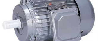
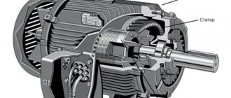
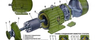
Device
To work with asynchronous motors and fully understand the principles of operation of such machines, it is necessary to familiarize yourself with the features of their design:
- The main parts of the unit design are the stator, which is stationary, and the rotating rotor, which is located inside it.
- An air gap separates both elements from each other.
- Both the stator and the rotor have a special winding.
- The stator winding is connected to an AC power supply.
- The rotor winding is inherently secondary, since it is not connected to the network, and the transfer of the necessary energy for it is carried out directly by the stator. This process occurs due to the creation of magnetic flux.
- The stator housing and the motor housing are one element that has a pressed core in its structure.
- in the grooves of the core . A special electrical varnish ensures reliable insulation of these objects from each other.
- The core winding is specially divided into sections that are connected into coils.
- The coils make up the phases of the motor itself , to which the phase from the supply network is connected.
- The rotor consists of a shaft and a core.
- The rotor core is created from assembled plates, which are made from a special type of electrical steel. On its surface there are symmetrical grooves, inside of which the winding conductors are located.
- , the rotor shaft performs the functions of transmitting torque directly to the drive mechanism of the machine.
- The rotors have their own classification; the short-circuited version has rods made of aluminum in its design. They are located inside the core, and at the ends they are closed with special rings. This system is called the squirrel wheel. In machines with the highest power, the grooves are additionally filled with aluminum, which increases the strength of the structure.
- Instead of a squirrel cage rotor, the design may have a phase type. The number of coils shifted at a certain angle relative to each other in such a system depends on the number of paired poles. In this case, the rotor pairs of poles are always equal to the number of similar pairs in the stator. The rotor winding is connected in a special way and resembles a star in shape, and its rays are output to the contacts of the slip rings, which are connected using a brush-type mechanism and a starting rheostat.
Download
I hope readers will forgive me for my free explanation of the processes - I tried to explain everything “on the fingers”. Who needs academic knowledge, please:
• V.L. Likhachev. Asynchronous electric motors. 2002 / The book is a reference book that describes in detail the design, operating principle and characteristics of asynchronous electric motors. Reference data is provided for engines of previous years of production and modern ones. Electronic starting devices (inverters), electric drives are described., djvu, 3.73 MB, downloaded: 7198 times./
• Bespalov, Kotelenets - Electrical machines / Transformers and electrical machines used in modern technology are considered. Their decisive role in the generation, distribution, conversion and utilization of electrical energy is shown. The basic theory, characteristics, operating modes, examples of designs and applications of electrical generators, transformers and motors are given., pdf, 16.82 MB, downloaded: 2345 times./
• MM. Katzman - Electrical Machines / Some say this is the best textbook on electrical engineering. The book discusses the theory, principle of operation, design and analysis of operating modes of electrical machines and transformers, both general and special purpose, which have become widespread in various branches of technology., pdf, 22.12 MB, downloaded: 2108 times./
• Electromash motor catalog / Asynchronous electric motors with squirrel-cage rotor - manufacturer’s catalog, pdf, 3.13 MB, downloaded: 1401 times./
• VEMZ engines catalog / Engine parameters and catalogue, pdf, 3.53 MB, downloaded: 1197 times./
• Dyakov V.I. Typical calculations for electrical equipment / Practical calculations for electrical equipment, theoretical information, calculation methods, examples and reference data., zip, 1.53 MB, downloaded: 2554 times./
• Karpov F.F. How to check the possibility of connecting several motors to the electrical network / The brochure shows the calculation of the electrical network for voltage fluctuations during the start-up and self-starting of asynchronous motors with squirrel-cage rotor and synchronous motors with asynchronous starting. The conditions under which starting and self-starting of engines are permissible are considered. The presentation of calculation methods is illustrated with numerical examples. The brochure is intended for qualified electricians as a guide when choosing the type of electric motors connected to a municipal or industrial power supply network., zip, 1.9 MB, downloaded: 1665 times./
• Operating manual for asynchronous motors / This manual contains the most important instructions for transportation, acceptance, storage, installation, commissioning, operation, maintenance, troubleshooting and troubleshooting for electric motors produced by Elektromashina. The operating manual is intended for three-phase asynchronous electric motors of low and high voltage series A, AIR, MTN, MTKN, 4MTM, 4MTKM, DA304, A4., pdf, 7.54 MB, downloaded: 2566 times./
• Catalog of AIR engines / Catalog of AIR engines - power from 0.12 to 315 kW; rotation speed 3000, 1500, 1000, 750 rpm; mains voltage 220/380 V, 380/660 V;, pdf, 1.07 MB, downloaded: 1076 times./
• Lomonosov, V.Yu.; Polivanov, K.M.; Mikhailov, O.P. Electrical engineering. / Lomonosov, V.Yu.; Polivanov, K.M.; Mikhailov, O.P. Electrical engineering. One of the best books on the basics of electrical engineering. The presentation begins with the very basics: it explains what voltage, current and resistance are, provides instructions for calculating the simplest electrical circuits, and talks about the relationship and interdependence of electrical and magnetic phenomena. Explains what alternating current is and how an alternating current generator works. It describes what a capacitor is and what an inductor is, what their role is in alternating current circuits. It is explained what three-phase current is, how three-phase current generators are designed and how its transmission is organized. A separate chapter is devoted to semiconductor devices: it talks about semiconductor diodes, transistors and thyristors; on the use of semiconductor devices for rectifying alternating current and as semiconductor switches. The achievements of microelectronics are briefly described. The last third of the book is entirely devoted to electrical machines, units and equipment: chapter 10 deals with direct current machines (generators and motors); Chapter 11 is devoted to transformers; AC machines (single-phase and three-phase, synchronous and asynchronous) are described in detail in Chapter 12; switches, electromagnets and relays are described in Chapter 13; Chapter 14 deals with electrical diagramming. The last, chapter 15, is devoted to measurements in electrical engineering. This book is an excellent way to learn the basics of electrical engineering, to understand the fundamental principles of the operation of electrical machines and units., zip, 13.87 MB, downloaded: 2730 times./
Another manual on motors: • Starting and protecting AC motors / Starting and protecting AC motors. Starting and braking systems for AC motors. Protection devices and fault analysis of AC motors. Guide to selecting protection devices. Manual from Schneider Electric, pdf, 1.17 MB, downloaded: 2108 times./
DC and AC motors
Depending on the electric current used, motors are divided into two groups:
- DC drives;
- AC drives.
DC motors are not used as often today as they used to be. They have practically been replaced by asynchronous motors with squirrel-cage rotors.
The main disadvantage of DC electric motors is that they can only be operated with a DC source or an AC-to-DC converter. In modern industrial production, ensuring this condition requires additional financial costs.
However, with significant disadvantages, this type of motor is characterized by a high starting torque and stable operation under conditions of high overloads. Drives of this type are most often used in metallurgy and machine tool construction and are installed on electric vehicles.
The operating principle of AC electric motors is based on electromagnetic induction that occurs during the movement of a conducting medium in a magnetic field. To create a magnetic field, windings flowing around currents or permanent magnets are used.
What is leakage current and what are the reasons for exceeding the charge leakage rate?
Leakage current is a quantity that characterizes the process of reducing the battery capacity due to both natural causes and malfunctions in the electronics of the machine or improper operation of electrical appliances.
In the worst case, the car may not start at all if the battery is completely dead, but this situation can only happen if there are serious malfunctions or some electricity consumers are left in working condition overnight. If the car owner makes it a rule to check whether power consumers are turned off, it is likely that major troubles will be avoided.
Leakage is a normal process, but there is a normalized leakage value that is allowed by the manufacturer. Most often, the norm ranges from 15-20 to 50 mA. On modern cars with a large number of consumers, this parameter may be higher.
You can measure the leakage current using a standard open-end wrench and a multimeter. Also remember to wear gloves. The algorithm of actions is as follows:
- turn off all consumers, including the DVR and anti-theft alarm;
- disconnect the negative terminal from the battery;
- connect a multimeter measuring current to the battery negative and the negative terminal;
- Compare the readings with the norm for your model.
Source: www.kolesa-darom.ru
Practical use
Power drives will only operate correctly if their starting characteristics are taken into account when selecting them.
High starting current poses a serious danger to electrical equipment. If measures are not taken to limit it, serious problems are possible.
The starting current can damage not only the motor itself, but also other electrical equipment installed on the same line with it. To solve this problem, you can use the following methods: