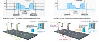
Street lighting surrounds us everywhere. An uninterrupted supply of light is provided to summer cottages, roads, bridges, and industrial areas. At night, lanterns, lamps, spotlights and façade lighting are used for this task. Controlling street lighting will significantly save both energy and financial costs.
Lighting automation poses several challenges. These include:
- Uninterrupted, interference-free street lighting.
- Energy savings, consumption within reason while maintaining lighting quality.
- Lower financial costs compared to other control systems.
Powerful lighting devices, thanks to automatic control, can be turned off and on at the right time. In addition, the system for organizing automatic work at night has other advantages.
Automation tasks
The main tasks of street lighting automation include:
- uninterrupted lighting of streets and highways;
- ensuring energy savings while maintaining lighting quality;
- reducing maintenance costs for lighting systems.
To implement these tasks, both autonomous equipment and automation systems are used.
What functions should street lighting perform?
External lighting, which today can be implemented in a wide variety of lighting installation options, must perform a number of functions:
- create high-quality illumination at night;
Street lighting at night
- is an indirect way to reduce the crime situation, both in individual areas and throughout the city;
- increases the safety of the movement of people and vehicles on sidewalks and roadways at night;
- creates beautiful lighting in the city center, including the facades of architectural structures, museums and theaters;
- acts as an element of anti-vandal protection of the city infrastructure from mechanical damage. For many city facilities (industrial buildings, educational institutions, public and municipal buildings, etc.), external lighting is part of the security system. The turning on of a light in a specific area may indicate that third parties have entered the protected area.
Street lighting is especially important in winter, when people return at night.
Lighting systems and their characteristics
The latest elements of lighting systems are LED lamps, which are very economical and reliable. But converting street lighting to such light sources will require a lot of time and expense. In the meantime, most streets are illuminated by gas-discharge lamps.
Ballasts are used to control such lamps. There are two types of ballasts:
- induction;
- electronic.
Using an induction ballast, a current surge is created in the circuit, due to which, at the moment of switching on, a high voltage of 2-3 kV arises and the gas-discharge lamp is ignited. During operation of the lamp, such a ballast, which is a choke, limits the power.
Induction ballast has the following disadvantages:
- the presence of a bulky throttle and an unreliable starter;
- light flickering at network frequency (strobe);
- low efficiency.
At the same time, ballast of this type increases the phase shift (reduces cos φ). To correct this effect, you have to turn on additional capacitors and use back-to-back lamp circuits.
An electronic ballast is an electronic device that ignites a lamp and maintains the voltage required for combustion at its terminals.
The electronic ballast circuit includes the following blocks:
- filter;
- rectifier with smoothing filter;
- inverter;
- throttle.
The filter is designed to filter out interference coming from the network and interference that occurs in the lamp power circuit. The rectifier is designed to produce constant voltage that powers the inverter.
The inverter generates oscillations with a frequency of 10 - 20 kHz. The load of the inverter is a transformer in which voltage is generated to ignite the lamp, as well as voltage to maintain combustion.
When using electronic ballast:
- flicker is eliminated;
- the brightness of the lamp radiation increases;
- the dimensions of the device components are reduced;
- efficiency increases;
- when using pulse width modulation mode, it is possible to adjust the brightness;
- The service life of the lamps is increased due to the programmed ignition start. In this case, the cathode of the lamp is first heated, and then the arc is ignited.
Operating principle
The connection diagram for a photo relay for street lighting includes a sensor, an amplifier and an actuator. Photoconductor PR1 changes resistance under the influence of light. At the same time, the magnitude of the electric current passing through it changes. The signal is amplified by a composite transistor VT1, VT2 (Darlington circuit), and from it goes to the actuator, which is the electromagnetic relay K1.
In the dark, the resistance of the photosensor is several mOhms. Under the influence of light it decreases to several kOhms. In this case, transistors VT1, VT2 open, turning on relay K1, which controls the load circuit through contact K1.1. Diode VD1 does not allow self-induction current to pass when the relay is turned off.
Despite its simplicity, the photo relay circuit is highly sensitive. To set it to the required level, resistor R1 is used.
The supply voltage is selected according to the relay parameters and is 5-15 V. The winding current does not exceed 50 mA. If it is necessary to increase it, more powerful transistors and relays can be used. The sensitivity of the photo relay increases with increasing supply voltage.
Instead of a photoresistor, you can install a photodiode. If a sensor with increased sensitivity is needed, circuits with phototransistors are used. Their use is advisable in order to save electricity, since the minimum response limit of a conventional device is 5 lux, when surrounding objects are still distinguishable. The threshold of 2 lux corresponds to deep twilight, after which darkness sets in 10 minutes later.
It is advisable to use a photo relay even with manual lighting control, since you can forget to turn off the light, and the sensor will “take care” of this on its own. It is easy to install and the price is quite affordable.
Control methods
Street lighting can be controlled in the following ways:
- manual;
- light sensor;
- time relay;
- microprocessor systems.
Manual control of street lighting is turning the power on/off according to a certain schedule directly at the substation by workers. The disadvantage is the involvement of additional personnel and inconvenient working conditions.
The light sensor controls the switching on of lamps based on the intensity of natural light from the sun. Flaws:
- limitations when calibrating the sensor;
- exposure of the sensor to dust, dirt and snow;
- impossibility of using energy-saving methods.
Photo relay
The time relay is oriented towards the specified time parameters. This leads to the main disadvantage of such street lighting control:
- constant adjustment of relay settings, taking into account the length of day and night according to the seasons.
The most advanced control systems are those that use processors and, in particular, automatic control systems (ACS). Typical automated control systems include:
- server;
- automated workstations;
- modems and communication lines with control objects;
- cabinets and light source control units.
Solution
Modern LED lamps, microcontrollers with a Wi-Fi module and the Internet of Things make it possible to solve the above problems and provide a high level of automation, reduce the complexity of installation and infrastructure support, and increase the accuracy of device control.
The developed urban lighting control system consists of the following components.
- Control units for lighting lamps and electricity meters.
- Central device management server.
- Operator web interface.
- Mobile web interface for field engineer.
How does the ACS work?
The street lighting automated control system performs the following tasks:
- automatic and manual control. Includes both dispatcher commands and recording of light sensor readings, etc.
- control of the operation of starting devices;
- automatic taking and recording of network readings. Thanks to this, it is possible to analyze the operation of the lighting system, including identifying burnt-out lamps, directly at the control center, without going to the site.
When controlled according to a schedule, the lamps are turned on according to the date and time of day. After entering the schedule, the ACS can control the lighting operation for a whole year without operator intervention.
After being generated by the software, the control command is transmitted via the communication line to the ballast, which in this case represents the actuator.
The following are used as communication lines:
- low-current communication lines (twisted pair);
- radio communication;
- cellular;
- RF signal transmission via cable.
In each case, the advantages and disadvantages of the communication line are taken into account. For example, when using twisted pair, you can send commands to each lamp, but to do this, each lamp must have its own unit installed. In this case, such a line requires mandatory adjustment of the timer.
A communication line using GSM does not require large expenses for its implementation, but for its operation you need SIM cards and you need to pay the operator for its use.
Such a communication line only works within the coverage area of the telecom operator, and its reliability depends on the load on the GSM system by other users.
Using power cables to transmit commands can lead to errors if the cable is broken. The length of such a communication line should not be more than 1 km.
When using a radio channel, transceiver equipment is required, the operation of which may be affected by radio interference or influenced by radio shadow zones.
Depending on the service capabilities, a twisted-pair communication line can be used in a small town or area of a large city, a GSM communication line in a city or the nearest suburb, a power cable communication line within a block, and a radio line in a city, suburb and along highways.
Control over area lighting
If finances allow you to stretch a separate cable to each lamp with a relay on the site, then one control cabinet will be installed inside the house, and another one at the gate. But such a shield must operate in parallel with the second one, which means that each unit will consume the energy of a full-fledged cable channel.
Garden lights for lighting the area, are not afraid of water (IP66), have built-in motion sensors and a control panel
The following system would be optimal: the first cabinet is installed at the gate, and lights with motion sensors and photo relays located along the path are connected to its controller. The second cabinet is placed directly inside the room - remote control will be carried out from here. The scheme is simple: certain lamps are connected to the channel that goes to the control unit, and a signal is sent from the remote control.
A popular unit is one that controls the automatic lighting system and has a large number of additional capabilities. Among them are a circuit for providing illumination, remote control of a photo relay. The shield can also issue a command to automatically de-energize the perimeter of the house. And the most common and budget cabinet assumes the presence of 6 working channels, of which no more than 4 are usually used.
Lighting automation equipment
Along with automated control systems, the following devices are used to control the lighting of a street, house or suburban area:
- light sensor;
- Motion Sensor;
- time relay;
- astronomical relay;
- Dimmer.
Light sensor
The light sensor (twilight switch) is designed to automatically turn the lighting on and off depending on the illumination of the area.
The principle of operation of this sensor is that the light flux acts on a photosensitive element (photoresistor, phototransistor, photodiode), which is included in the electronic circuit. As a result of a change in the current flowing in the circuit, the relay included in this circuit is activated. The relay contacts open and the lamp turns off.
Main characteristics of the light sensor:
- load power or current;
- response threshold;
- response delay;
- degree of protection.
The most important parameter of the sensor is the load power. When choosing a sensor, it is necessary that the luminaire power is equal to or less than the permissible power. This power for most industrial sensors lies in the range of 1.5 -2 kW.
The sensor response threshold is determined by illumination. For most light sensors, this parameter can be adjusted. Its value ranges from 2 to 200 lux.
When setting the sensitivity of the sensor, it is necessary to take into account that illumination of 5 lux corresponds to darkness, at which individual objects can be distinguished, and with illumination of 2 lux, complete darkness occurs.
The response delay is designed to protect the sensor from false signals that occur, for example, when a shadow from a tree or headlights enters the sensor’s working area. This delay is 15-60 seconds.
When placing the sensor outdoors, it may be exposed to dust or moisture. Therefore, light sensors must have an increased degree of protection (no worse than IP44).
Motion sensors
Along with light sensors, motion sensors are used to automate street lighting control. Sensors can be either built-in or remote.
The principle of operation of such sensors is to respond to the appearance of a moving object. The most common infrared sensors use information about changes in light emission in the infrared range. The main parameters of such sensors:
- load power;
- range;
- viewing angle;
- response delay time.
After installing such a sensor, its parameters are adjusted. Most models of motion sensors are regulated by:
- sensitivity (SENS);
- illumination (LUX);
- delay time (TIME).
Using the first adjustment, the sensor's response range is set, using the second, the response threshold for illumination, and using the third, the delay time for turning on the sensor.
Timer
The timer turns the lighting on and off based on certain hours of the day. The disadvantage is the need to adjust the device due to the daily change in sunrise and sunset times.
A more accurate option is a digital astronomical timer, which has a pre-installed program for determining the time of sunset and sunrise based on the specified latitude and longitude of the location of the light source. In accordance with this information, the lighting is turned on and off.
Such a timer can switch a purely resistive load with a current of 16 A (for switching an inductive load this current is 4 A). To connect more powerful lighting lamps, you must connect a magnetic starter. Astronomical timers can be installed in a distribution board, and their degree of protection does not exceed IP20.
Dimmers
For small lighting systems for which it is not economically feasible to use centralized dimming of lighting lamps, autonomous dimmers are used.
For example, a dimmer type K2303 can switch lighting to a low-power mode at night (up to 75-50% of the nominal value). This allows you to save energy consumption.
The dimmer can work with both gas-discharge lamps and LED lamps. The device is installed in every street lighting fixture. Using special switches on the dimmer, the operating mode is set, as well as the time schedule for switching to reduced power. This type of dimmer can also work with a motion sensor. In this case, if there is no moving person or car in the sensor’s coverage area, the lighting lamps will light dimly, and when a moving object appears, they will light up at full power.
Automated street lighting control
The article examines foreign street lighting control systems, and also describes the development of the author and his colleagues, in which the significant functionality of foreign systems is complemented by an intelligent algorithm for monitoring the health of lamps, which allows to significantly reduce the cost of automation equipment.
Introduction
Street and highway lighting systems play an important role in ensuring the comfort and safety of citizens. Developers of modern automated street lighting control systems face the following main tasks:
o provide uninterrupted lighting to residential, public and industrial areas, highways and other ground transport infrastructure facilities. Uninterrupted lighting means the minimum time from the moment the lamps fail until they are restored to functionality;
o ensure savings in energy spent on lighting. As part of the description of street lighting control systems, we do not consider the energy efficiency of the lamps themselves, but analyze systemic ways to reduce energy costs while ensuring lighting quality;
o ensure that maintenance costs (mainly lamp replacement) are minimized.
Today, uninterrupted lighting is often ensured with the help of economic levers: organizations responsible for street lighting pay fines for exceeding the standard number of faulty lamps on their territory. Thus, the conflicting tasks of minimizing costs and optimizing service quality come into balance.
Traditional street lighting control systems
Today, the most common gas-discharge lamps for street lighting are filled with mercury or sodium vapor. Recently, there has been a tendency to switch to LED emitters, but this technology is not yet widely used. In traditional HID lamp control systems, ballasts or ballasts play a critical role. Ballasts limit power to rated levels and are widely used to implement simple control functions.
Induction ballasts (IB) generate a surge of current when power is applied, which is necessary to ignite the gas-discharge lamp. At the stage of stable glow, the induction ballast (also called magnetic ballast) limits the power to the lamp due to inductance reactance (the ballast itself does not heat up). The disadvantage of magnetic ballasts - the phase shift between current and voltage, i.e., a decrease in cos j - is corrected through the use of capacitors and various anti-phase switching circuits for several lamps, which also reduces the stroboscopic effect of flickering lamps at industrial frequencies.
Electronic ballasts (EB) are semiconductor devices that provide the required sequence of supplying ignition currents and maintaining voltage across the lamp. EBs usually consist of an inverter that converts industrial frequency currents into currents with a frequency of approximately 20 kHz. This provides a number of advantages: the stroboscopic effect is eliminated and the brightness of the gas glow increases due to constant ionization at an increased frequency. The brightness of the glow increases sharply (by 9%) at a frequency of about 10 kHz, and then gradually increases as the frequency increases to approximately 20 kHz. Operating at high frequencies also makes it possible to dramatically reduce the size of electronic components, increase their efficiency, and use a capacitor rather than an inductance to limit the current through the lamp, thereby minimizing electrical power losses. Modern electric lamps allow you to smoothly adjust the brightness of the glow using PWM and implement various modes of ignition of gas-discharge lamps:
o instant start: ignition of lamps without preheating the cathodes with a voltage pulse of about 600 V. From an energy point of view, this is the most effective method, but it leads to powerful emission of ions from the surface of the cold cathode, which shortens the life of the lamps when switched on frequently;
o quick start: simultaneous supply of ignition energy and heating of the cathodes. When operating in this mode, a certain amount of energy is spent on constant heating of the cathodes;
o programmable start: sequential energy supply, first for heating the cathodes, and then for igniting the electronic arc. This method ensures the longest service life of gas-discharge lamps, high efficiency and the maximum number of on-off cycles.
EBs are often equipped with remote control controls. LonWorks, DMX-512, DALI, DCI are usually used as network protocols. For example, the widely used LonWorks protocol developed by Echelon Corporation can use a power cable as the transport medium that supplies power to the lamp. This protocol defines addressing, routing, and control methods. Thus, the EB is a kind of “switch” for street lighting lamps, providing energy saving, extending lamp life and remote control. To automate the switching on and off of street lighting lamps, light level sensors are most often used. The operating algorithm of such systems is extremely simple: when the brightness level decreases below a specified threshold (twilight), the lamps turn on, and turn off when the operating threshold is exceeded.
The disadvantages of such systems include difficulties in calibrating sensors, sensitivity of sensors to contamination, and the inability to implement energy-saving operating algorithms (for example, dimming or turning off some lamps in the dead of night, when full lighting is not required). An interesting method of controlling street lighting in accordance with the external light level was proposed by the Korean company Stwol. Instead of a photosensor, a built-in GPS receiver and a computing device were used. Knowing the coordinates of the geographical location of the street lighting controller and the astronomical time received from the satellites of the global positioning system, the computer determines the exact time of sunset and sunrise. The controller turns on the lighting 15 minutes before dusk (the moment when the center of the sun is 6° above the horizon) and turns off the lighting 10 minutes after sunrise at a given point on the globe. Obviously, this system is insensitive to optical contamination and inaccurate calibration of photo sensors.
An alternative method of automatic control in street lighting systems is to use a schedule for turning the lighting on and off. With this approach, the controller turns the lighting on or off based on the date, day of the week (weekdays or weekends) and time of day. This method is simple and effective and allows you to implement, among other things, energy-saving lighting schemes, take into account the need for holiday illumination, etc.
Methods for remote control of street lighting
Automatic street lighting control systems usually operate under the control of a zone controller or server. Depending on the control algorithm, the controller generates a signal, for example, to turn on a group of street lights. The following means are used to transmit this signal to actuators (usually electronic ballasts for street lamps):
o low-current signal lines (twisted pairs, RS-485, Ethernet, etc.);
o radio channel;
o GSM channel;
o RF signal transmission via power cable.
A comparison of the advantages and disadvantages of each method is given in Table 1. Regardless of the method of transmitting the remote control signal, modern automatic street lighting control systems (see Fig. 1) are built according to a three-level architecture:
o direct control unit for a lamp or group of lamps in a street lighting lamp;
o zonal level control cabinet (street or block);
o central server of the territory.
Table 1. Comparison of control signal transmission methods
| Low current control | GSM channel | Power transmission lines | Radio channel | |
| Addressing (economically feasible) | Possibility of controlling individual lamps | Group control only | Group control only | Group control only |
| Control method | Digital control protocol, e.g. based on scheduling | Phone call or SMS to the controller in the control cabinet | Control via power cable connected to the controller in the control cabinet | Radio signal transmission from the control room to the receiver in the control cabinet |
| Factors affecting reliability | Timing error accumulation | Dependence on the load on the public network of the GSM operator. Impossibility of control in case of network failure (overload). | Risk of erroneous control when it is impossible to control the state of power lines (for example, in the event of an insulation breakdown). In case of failure, manual cable switching is required. | Radio shadow zones, radio interference may make it impossible to receive a control signal |
| Labor costs | High labor costs when setting up a calendar schedule | Low labor costs due to the use of a public network | When individually controlling lamps, cabling is labor-intensive | High labor costs when installing transceivers |
| Territory coverage | The calendar schedule requires reference to the city/region | Control is only possible within the coverage area of the cellular network | The need to lay a separate cable to each control point. The length of the control power cable cannot exceed 1 km. The control cabinet capacity is limited. | Control is possible only in the area of reliable radio signal reception. Relay transceivers are required to expand the reception area. |
| Territory size | City district, small town | City and nearest suburbs | Limited area (block, etc.) | City and suburbs, area along highways |
| Cost factors | Individual control unit in each lamp | Subscription fee and fee for connection, message transfer, etc. | Cost of laying individual power cables | Cost of control room equipment, relay stations and receivers |
| Factors Affecting Maintenance Costs | The timer needs to be adjusted constantly | High costs for repairing electrical equipment | Qualified dispatcher required |
In such a system, any lamp can be turned on or off by a signal from a central server. This is achieved by using direct lamp control units (see Fig. 2). The price to pay for such convenience is the high cost of the hardware. If the radio frequency method of transmitting signals to block 1 is implemented, each block must have its own address (for example, an IP address within the TCP/IP protocol). When implementing urban street lighting projects, the number of blocks and, accordingly, addresses can be 50–100 thousand. The task arises of initially setting addresses and binding to the area to display the status of the lamp on the computer screen. This problem is solved, for example, in [1] as follows: the control unit is assigned a default address upon delivery. The central server periodically polls devices. The network protocol ensures that if the addresses match, only one device will be selected. If there is a block with a default address, the central server sends a command to such a device to set a unique address, and the operator binds this address to the territory. Obviously, the initial configuration procedure is very labor-intensive.
The system of individual control of each lamp via a GSM channel is not used in practice due to the high cost of GSM modems and the need to install individual SIM cards in each unit and subsequent cost accounting. Therefore, the GSM channel is used only at the level of the zonal control cabinet. Below we will show how the development of the author and his colleagues overcomes this drawback of control systems based on the GSM channel.
The three-level principle of constructing lighting control systems extends not only to methods of remote control of turning on or off individual lamps, but also to the functionality of the system. For example, DotVision (France) offers the following options for controlling street lighting:
o individual control using intelligent electronic components;
o zone lighting control with remote power control;
o zone lighting control with telemetry.
The first option provides maximum control capabilities with addressing of each street lighting lamp. The system consists of an electronic unit with a data transceiver via a radio channel or an RF signal via a power cable, a zone controller in an outdoor control cabinet and a territorial server. This option provides maximum opportunities for energy savings and the highest quality of service to the public by monitoring the condition of each lamp.
The second option is a compromise between the cost of the system and the potential for energy savings. This solution includes a power variator installed in the zone control cabinet and a telemetry system based on Modbus or LonWorks protocols. The territorial server transmits control signals and collects telemetry information from zonal controllers.
The third option does not save energy, but includes a zone controller with fault detection, telemetry and remote lamp on/off functions. The territorial server transmits control signals and collects telemetry information from zonal controllers. The results of using the described options for automating street lighting control are shown in Table 2
Table 2. Results of using various options for automation of street lighting control
| Individual control with intelligent electronic ballasts | Zone lighting control with remote power control | Zone lighting control with telemetry | |
| Energy consumption | Savings up to 46% in power, up to 40% in cost (depending on the price of electricity) | Savings up to 26% in power, up to 15% in cost | |
| Maintenance | Save up to 20% on lamp replacement, up to 80% on field repair work | Save up to 30% on field repair work | Save up to 30% on field repair work |
| Environmental impact | Reduced CO2 production by 50% (due to energy savings) | Reduced CO2 production by 20% (due to energy savings) | |
| Quality of public service | Detects 99% of faulty lamps within 12 hours | Detection of 30% of faulty lamps within 12 hours | Detection of 30% of faulty lamps within 12 hours |
| Average payback period | 7 years further significant savings | 7 years further moderate savings | 6 years further minor savings |
| Additional benefits | Possibility of using the system to monitor the environment on the territory (temperature, humidity, air pressure, air pollution, noise level). |
Functions of automatic street lighting control systems
Let's look at a modern street lighting control system using the example of a system being created in Oslo. This is the first large-scale street lighting retrofit project in Europe. It provides for the installation of about 55 thousand electric units over three years, controlled via existing power circuits using technology from Echelon (developer of the LonWorks protocol). In April 2006, the first 6,500 lamp posts were already installed. The goal of the project is to halve energy costs while improving the quality of service to the population and reducing maintenance costs. The cost of installing the system will be recouped in five years.
So, the project provides for the replacement of 55 thousand outdated magnetic ballasts with smart electronic components produced by SELC Ireland Ltd. (Ireland). Ballasts support data exchange via power cable using the LonWorks protocol. Data from the energy supply is concentrated in approximately a thousand Echelon i zone controllers. LON 100 Internet Server. The controllers interact with the central server via GPRS wireless technology (using the cellular operator's network). The central server uses DotVision Streetlight Suite and Philips StarSense software to collect and analyze information. Intelligent electronic devices have the following capabilities:
o control the switching on and brightness of the lamp;
o data exchange via HF through power cables;
o measuring the current through the load (lamp);
o measurement of ambient temperature;
o measuring the level of environmental illumination;
o measurement of the phase shift between the current and supply voltage of the lamp.
Zone controllers perform the following functions:
o data exchange with electronic units via RF signal transmitted through power cables;
o routing of control signals for electronic ballast units;
o data exchange with the central server via GPRS channel;
o registration and accumulation of measurement data on energy consumption received from electronic ballast units;
o collection and accumulation of information from weather sensors and traffic density sensors;
o calculation of the level of natural light from the sun and moon based on the built-in astronomical clock;
o taking into account the operating time of lamps in the on state to determine the life of the lamps;
o control of the brightness of individual lamps (via ballast units) based on an algorithm that takes into account the time of year, weather conditions and traffic density;
o monitoring the presence of supply voltage in the control cabinet;
o measuring currents in power cables feeding lamps;
o measurement of induced currents;
o detection of leaks due to insulation damage;
o measurement of corrosion potential;
o transmission of alarm messages to a central server when emergency events or lamp failures are detected.
The central server has the following capabilities:
o web portal for monitoring the status of all system components and direct control of zones and individual lamps;
o presentation of information on geographical maps;
o analysis of the behavior of system elements;
o fault detection;
o measurement of energy consumption at a territorial, administrative and geographical level;
o planning the replacement of lamps on a territorial or administrative basis, based on taking into account the actual operating life of each lamp and information about failures;
o operational management of zones, groups and individual lamps, for example, for the purpose of replacing lamps or checking insulation.
Advantages of using a GPRS channel for communication between system components:
o minimal costs for installing equipment;
o wide territorial coverage in the city;
o high degree of data protection;
o use of the TCP/IP protocol all the way from the server to the end device;
o low cost of data transfer (depends on the volume of traffic, not on the connection time);
o availability of free volumes up to 1 MB per month in prepaid plans.
Amplex (Denmark) offers its solution for controlling street lighting, built entirely on the basis of a GPRS channel. Control is limited to the zone level when AmpLight controllers are installed in a cabinet controlling a group of up to 50 lamps. In this case, high energy savings are achieved by reducing brightness late at night, but there is no possibility of detecting the failure of individual lamps.
Domestic developments
(Moscow) in collaboration with FF-Automation OY (Finland) developed a control and monitoring system for street lighting based on Autolog GSM controllers and the GSM Control SCADA system server. This system overcomes a serious limitation present, for example, in the Amplex system described above, which is also based on a GSM data network. The relatively high cost of GSM controllers does not allow them to be used to control individual lamps. Typical zone control systems, however, cannot reliably detect burnt-out lamps because they are typically focused on measuring the current in the power circuit supplying a group of 30–50 lamps. If one or two lamps fail, the possible scatter in the network voltage does not allow tracking the decrease in current in the group circuit.
The GSM Control system uses a voltage sensor together with a current sensor in a group to detect lamp failure. Current and voltage measurements are statistically processed, and therefore errors associated with the spread of lamp characteristics and their changes over time are smoothed out. The system is able to detect the failure of one lamp in a group of 30 lamps, which makes the use of a GSM controller economically justified. When a lamp in a group fails, the zone controller sends an alarm to the server, and the repair team is able to visually detect the faulty lamp in a small section of the road where the specified 30 lamps are installed. This is much more economical than organizing patrols of the service organization's service area at night to detect burnt out lamps.
The system detects a lamp that has not yet failed, but whose resource has been exhausted. Gas discharge lamps switch to intermittent mode before they stop glowing. Digital filtering of measurement data makes it possible to detect this operating mode of one lamp in a group, and transmit an alarm signal to a central server for replacement planning.
GSM Control can use Google Maps for a cartographic presentation of information that combines high-resolution satellite imagery with a vector map of roads and streets (see Figure 3). The system also provides access to telemetric information of each zonal controller in graphical and tabular form with the ability to upload to Excel.
The GSM Control system provides a rich set of functions for building a modern automatic control system for street lighting (see Table 3).
Table 3. Main functionality of the GSM Control system
| Function performed | Implementation method | Notes |
| Turning street lighting on and off | On schedule | Sports facilities, city squares and other objects can be turned on either by a signal from a light sensor or by a schedule. It is not always necessary to maintain full lighting throughout the night. |
| Often one of the phases is switched off late at night to save energy. Or they reduce the voltage on the lamps with transformers. Both of these modes are supported by our system. | ||
| Based on light sensor signal | The most commonly used method of controlling street lighting. In our system, the light sensor can be connected to each individual controller (if necessary) | |
| Typically, a master controller is used, equipped with a sensor, and controls a number of slave controllers. In our system, control from the master to the slaves is carried out by non-charged (free) telephone calls, i.e. wirelessly. As an additional benefit, we indicate the gradual switching on of groups of lamps, which reduces peak energy consumption | ||
| There is a mode for automatically turning on the slave controllers in the event of no command from the master controller, for example, 10 minutes later than the average time the lamps were turned on in recent days | ||
| Manual control | Necessary, for example, during repairs (replacing lamps). The electrician can send a manual shutdown signal from his mobile phone, without requiring a remote control in the field. There are, for example, service modes for turning on lamps for 15 minutes with automatic shutdown for visual detection of burnt out lamps | |
| Features are provided to prevent unauthorized switching on/off of lighting | ||
| Operating modes and parameters are entered using a graphical interface via a computer using the GSM-Control development software package | ||
| One control unit (controller) can control 6 phases. This includes measuring current in 6 phases and voltage in two three-phase lines. This allows one controller to control six separate groups of lamps, approximately 30 lamps in each group. | ||
| Functions for monitoring the condition of lamps and signaling the need for replacement. | The system uses statistical studies to optimize lamp replacement based on labor costs to optimize system maintenance costs. | |
| The system monitors lamp aging and plans replacement of lamps that are reaching the end of their service life. | ||
| Through the use of statistical methods for processing three-phase measurements, the system is able to detect the failure of individual lamps in groups of 30 lamps. This allows you to use one controller per such group, which reduces the cost of the system compared to individual controllers by 4 times | ||
| Security Features | The lighting is automatically turned on in case of failures in transmitting commands via a wireless channel | |
| A minimum time of keeping the lamps on is guaranteed to be 15 minutes. | ||
| The system is protected from unauthorized control | ||
| The system reduces the peak load on the power grid when the lights are turned on | ||
| The system generates emergency messages in cases | Turning on lamps unnecessarily | |
| Lamps not turning on when commanded to turn on | ||
| Light sensor malfunction | ||
| Slave controller failed to receive command | ||
| Failure to comply with the command to reduce voltage |
Conclusion
From the above review it is clear that the greatest successes in building modern resource-saving street lighting control systems have been achieved by the countries of Northern Europe. Probably the reasons are the high price of electricity and relatively short daylight hours (in winter). Russia is in even more stringent conditions in terms of daylight hours. And although our cost of electricity is lower than in Europe, we should not neglect the possibility of savings when modernizing road infrastructure and housing and communal services. The development of mass production of modern ballast blocks with the functions described in this article is also promising. In Europe alone, it is estimated that 120 million ballasts need to be replaced, with EU Directive (No. 000/55/EC) mandating the use of electronic ballasts to save energy. The global market is estimated at 500 million units. This is a good chance for domestic developers of electronic components!
Literature
1. US Patent No. 7 October 17, 2006
, www.
conclusions
- To control street lighting, which uses gas-discharge lamps with induction or electronic ballast, both individual autonomous automation equipment and complex automated control systems can be used.
- Light sensors, motion sensors, time relays, and dimmers are used as autonomous lighting automation devices.
- To ensure communication between the lighting control point and the luminaires, low-current communication lines, cellular communication lines, communication lines using power cables and radio lines can be used.
How is street lighting control implemented?
PowerLine
Electronic lighting control and monitoring carried out by exchanging data via electrical wires without the need to install additional data cables and maintaining all the functional characteristics of the lighting system.
To use PowerLine technology, the primary side of the lighting system must be equipped with a PowerLine transmitter, and its secondary side, i.e. the lamps themselves are the corresponding receivers. As a rule, luminaires are equipped with traditional dimmable ballasts with a DALI or 1-10 V interface. PowerLine allows communication between the control element and a conventional dimmable luminaire without the need for an additional communication network. In the same way as in the case of using the DALI protocol, the lighting system retains its full functionality, and at the same time the controller from his console can, for example, adjust the lighting intensity on less busy streets at appropriate intervals, thus achieving significant energy savings. Or vice versa, using a PC to provide additional local lighting in the event of cultural events in an illuminated part of the city or town in the evening.
Sensors and switches
Specialist control sensors are divided into two types:
- motion sensors;
- devices for determining the level of illumination.
The equipment operates in automatic mode. Sensors detect thermal radiation, which triggers the lamps. The sensors operate using infrared radiation, which does not pass through various types of obstacles.
Often, homeowners purchase products that are triggered by remote controls that send out infrared radiation. A special remote control starts the lamps. Such switches have strengths:
- control the light from anywhere in your home;
- there is software that allows you to control devices via a smartphone;
- the ability to connect adapters that convert infrared rays into radio frequency ones.
Remote switches can be supplied as motion-sensing sensors or sound-sensing products. The former trigger the light as soon as a person enters the room, and the latter react to individual sounds, for example, clicks or voices. You can forget about searching for the switch and walking across the room to it to turn off the electricity.
Electronic control system DALI
The name of the electronic control system - Digital Addressable Lighting Interface - implies that we are talking about electronic control of lighting systems, which makes it possible to reduce the intensity of the luminous flux of lamps within an acceptable range.
This standard digital lighting control protocol uses two-conductor, non-polarized wires to install this standard digital lighting control protocol. This type of outdoor lighting control requires the luminaires to be equipped with electronic ballasts with a DALI interface. The two main advantages of this control method are the possibility of independent dimming and monitoring of lighting installations. Dimming can be carried out in any range established for a specific type of lamp. For gas discharge lamps this range is 60-100%, for LEDs - 10-100%, and for fluorescent lamps - from 1 to 100%. Monitoring allows for operational control of luminaires, thereby contributing to the correct operation of the entire lighting system. In addition, the DALI electronic control system allows you to combine luminaires into separate groups or control each of them separately. To control the DALI system depending on time, it is necessary to use controllers that have this function. Calling up light scenes, rearranging and changing functional characteristics does not require any intervention in the luminaires or wiring. They can usually be carried out from the same location using a PC. To increase visual comfort and quality of lighting, smooth control of lighting intensity is used, which is practically invisible to road users and pedestrians.of it.
Types of SHUO
Today there is a huge variety of SHUO in terms of materials of manufacture, housing properties, standard sizes and installation method (pole and foundation). For example, for outdoor use, manufacturers of electrical equipment produce special anti-vandal cabinets made of plastic or metal.
SHUO can be used to solve several problems:
- management of lighting units on urban and intercity roads;
- control over the operation of energy-saving networks using special automated parts;
- management of architectural and landscape lighting of park alleys, city streets, fountains and other objects;
- automatic operation of security systems, including alarms and video surveillance;
- traffic light regulation;
- control over the operation of communication systems (various telecommunications, Internet and low-current devices).
The choice of control method (read above) depends on the purpose, operating conditions, and properties of the control unit. Let's look at a few main varieties.
Option one - EP-SHUNO-1
This electrical element can be used for automatic, manual, local or remote control of lighting networks and other installations at industrial and administrative facilities. The cabinet of this model can turn on and off lighting installations using signals from a photo relay when the illumination reaches a certain threshold value.
Systems can be turned on and off at set periods of time depending on the set program. Using the buttons located on the case, the network can be turned on and off manually at any time. The same can be done from control rooms using telemechanics equipment.
Option two - EP-SHUNO-I170
This equipment, in addition to standard functions, can quickly switch on and off electrical circuits, the number of which can be no more than six per hour. The device is manufactured according to standard circuits and is equipped with standard low-voltage devices. Depending on the individual wishes of the customer, the cabinet can be re-equipped, the dimensions and electrical circuit can be changed.
The basic configuration of such cabinets contains four main blocks:
- input unit with switch, disconnector and fuse;
- metering unit with measuring current transformer, test box and meter (it is chosen by the customer);
- switching unit with contactors, intermediate and temporary relays, photo relays, mode switches;
- assembly of outgoing lines with fuses on special holders.
Option three - EP-SHUNO-3
In terms of purpose they resemble the previous model of lighting control cabinets - EP-SHUNO-I170. In contrast, in this model the rated values of currents on the input and output groups are significantly increased, many more protected lines and a special automated automated control system are used.
Using this model, you can perform separate control of several lighting modes, including street, architectural and advertising. The equipment can be supplemented with vertical holders or switches with fuses.
Option four - VRSH-NO-M8
Such equipment is used to automatically or manually turn on/off city lighting in the evening or at night. The cabinet is also capable of accounting for electrical energy and controlling lighting using telemechanics devices. Inside there is an additional subscriber compartment, and the basic package includes the following units:
- input panel with switch, fuse box and instrument transformer;
- distribution panel with contactors, strip holders;
- telemechanical metering panel with meter, box and telemechanical control system;
- subscriber compartment with modular circuit breakers that protect network users.
For installation and operation of these models there is no need to use concrete or metal structures. The cabinet can be placed on supports. If the SHUO is installed in a block distribution point, then it can be divided into several functional buildings.
Option five
Such devices, similar to the previous ones, automate the process of controlling lighting systems, monitor and diagnose external lines. They are used in energy-saving and investment networks in order to increase the energy efficiency of outdoor lighting systems.
Sensors, monitoring devices and control devices
Sensors of the power supply and lighting control system are used to collect and transmit information about the presence of people in the room, light level, temperature on heating devices, etc. The data is transmitted to the control system, and based on their readings, the automation system activates the appropriate operating mode.
Sensors can transmit threshold, discrete or analog signals, depending on this, an expansion device is selected to include them in the automation system.
Sensor readings are presented to the dispatcher through the monitoring system. In general, the monitoring system is designed to perform the following functions:
- Continuous monitoring of the condition of equipment installed at the facility;
- Issuing warning and emergency alarms to the control panel;
- Remote control of serviced equipment from the dispatch console;
- Providing collected information on the control panel in a user-friendly form;
- Archiving information in a database;
- Keeping an event log of emergency and warning alarms, as well as the actions of maintenance personnel (dispatcher);
- Generating reports based on user templates based on the collected data.
Use a modification of lamps with an astro-timer function (local control system).
The astro timer, depending on the settings, can independently turn on, turn off and dim at a certain point in time, for example at twilight, or an hour before sunset, or 2 hours after dawn, or when setting other values.
These parameters are set either at the factory before shipping the order, or during installation of the products at the site of their use.
Fig.2. Example of programming timer operating modes
This solution allows you to save on connecting additional devices and increases system fault tolerance due to a reduction in the number of components used.
Disadvantages and advantages of infrared sensors
The disadvantages of using motion sensors include the possibility of false alarms (reaction to warm air, sunlight), deterioration of work on the street due to precipitation, failure of the device to operate when a person’s clothing does not transmit infrared radiation, constant turning off of the light after 10-15 seconds as soon as motor activity decreases.
The advantages of sensors include the ability to control electrical energy consumption and, as a result, reduce financial costs, safety for human health, and ease of use.