General principles for installing light switches
Installation of a simple lighting system and control devices is carried out during renovation work in the room. For hidden wiring, before finishing finishing work, the cable is laid in grooves and places are prepared for the installation of switches. In this case, switching of switches, lighting devices and power lines is carried out in installation junction boxes. Such boxes can be located in special niches in the walls, hidden in the floor or behind a suspended ceiling.
In some cases, for example, in wooden houses, the installation of hidden wiring is prohibited by regulations, so in such rooms installation is carried out openly after finishing the room (using cable ducts or special corrugated tubes).
The general principle of connecting switches is in most cases the same: the switch serves to break the phase on the line, and the zero is connected directly to the lamp. Why phase and not zero? This requirement is directly stated in the PUE, which states that the possibility of breaking one neutral conductor without disconnecting the phase conductor must be excluded. This is directly related to safety measures when operating lighting devices. When a device is disconnected from the mains using the switch, there must be no voltage applied to it so that it can be safely repaired or the lamp replaced.
"Russian Smart Home"
However, even in our native land there are prophets. The Russian company is already producing a version of the “Smart Home” adapted for our conditions. This is the “InDIUs” series, which stands for Intelligent Remote Actuator Device.
According to the developers, the main advantage of InDIUS over existing systems is its modular principle. Devices can be installed from room to room, from room to room, as needed or financially possible. But the main thing is that the system is being developed specifically for Russian electrical networks with their peculiarities.
Another distinctive feature of the Russian system is its ease of installation and flexibility of management. In particular, a lighting control system based on a domestic development allows you to control any number of lamps from any number of points, while requiring almost no changes to the existing electrical wiring. This is due to the use of light and motion sensors. And, as usual, the paradoxical use of incandescent lamps and daylight together will save energy and the resource of the latter...
As they say, “and then Ostap got carried away.” The Russians did not find the already created Smart Home system capable of competing with foreign developments to be enough. In the near future, it is planned to supplement the development with a module that understands voice control commands.
It is gratifying that the choice of lighting control schemes today is very large. Among the options available on the market, everyone can choose the one that suits their requirements, tastes and wallet. In a word, every person is free to choose their own level of comfort at work and at home! But at the same time, we should not forget about the ecology of our wonderful Planet...
Connection diagrams for switches and lamps of various types
The choice of connection diagram depends on the number of lighting fixtures and points to control their operation. Below we will look at the most common of them.
Single-key switch - a circuit for turning on one or more lamps at the same time
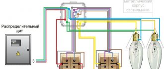
The most commonly used lighting connection option is a single-key switch. Using it, you can turn on and off both one lighting device and several at the same time. Such a switch is mounted in a standard socket box, in case of hidden installation of electrical wiring. Or it can be overhead when laying the cable in an open way. Installation of electrical wiring and connection of lamps and switches occurs in the following sequence:
- The power cable is laid from the electrical panel to the distribution box above the location of the future switch;
- A place is prepared for installing the switch and a two-core wire is supplied from it along the wall, strictly vertically, to the junction box;
- From the distribution box to the lighting devices (regardless of the number of lamps), an electric cable is supplied in a three-wire version (if it is necessary to ground the device) or in a two-wire version (without grounding);
- The switch is installed according to the diagram indicated on the device;
- In the distribution box, power lines, lamps and switches are connected according to the diagram for a single-key switch.
My implementation of automatically turning on the light in the toilet (and without Arduino)
Hi all! Articles about the implementation of a Smart Home appear and appear on Habré. The most important problem (or just for me) is turning on/off the light in the bathroom. It doesn’t seem like a tricky thing - but there are so many options. After reading the articles, including here and here, I thought, “But everything could be simpler.” This worm has been sharpening me for about six months. And so, when I became more free with work, I matured. I will say that I have liked to do both programming and radio design since school. Microcontrollers gave real joy - everything at once. But Arduino isn’t here, not because I hate it, it’s redundant for this task, or because I want to be different from everyone else, I just haven’t gotten around to it yet (or it’s gotten to me). Let's return to our sheep (or to our light, or to our toilet). For me personally, drawing a technical specification in my head (yes, drawing it when you can’t even formulate it, let alone write it down on paper) is much more difficult than implementing it later. After weeks of thinking, this is roughly what I came up with:
- the light should turn on when I open the door (for example, I walk in);
- the light should turn on when I close the door (I went into the bathroom with the door open and closed it behind me);
- the light should turn on when I enter without touching the door (I stopped by to wash my hands);
- auto-turn off the light after a certain time;
- The lights shouldn't turn off when I'm inside and don't even move.
It seems like everything is logical and simple, but I didn’t find a beautiful solution in any of the articles I came across. The simplest thing is a motion sensor. It turns on the light when someone is there and turns it off after a while. For my purposes, all it needs is a reed switch - to monitor whether the door is open or closed. I don’t understand why manufacturers haven’t gotten around to this yet. Or did they reach it, but didn’t it reach me? The algorithm is simple:
- if the motion sensor is triggered, turn on the light;
- if the state of the reed switch has changed (the door has opened/closed) - turn on the light;
- if the motion sensor is triggered when the door is closed (the reed switch is closed), do not turn off the light until the door is opened;
- Well, turn off the light after a while.
Now the technical requirements are clear, I need:
- Motion Sensor;
- reed switch;
- MK to manage this mess.
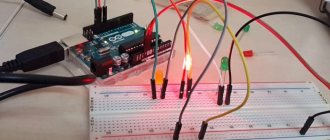
I bought the cheapest DD (infrared), some kind of reed switch, ATTiny2313.
We disassemble the motion sensor, we see inside:
control board with infrared receiver and mirror in the middle and:
PSU and relay. I was lucky, the DD has everything you need: a relay, a transistor for matching, the rest of the wiring (even a diode). When the sensor is triggered, a TTL signal is issued; it is enough to intercept it and transmit the signal from my MK instead. I drew a diagram in ISIS (if done, it’s beautiful) Diagram
I wrote a program in BASCOM-AVR:
Code
$regfile = "attiny2313.dat" $crystal = 4000000 $hwstack = 40 $swstack = 16 $framesize = 32 Config Porta = Output Config Portb = Output Config Portd = Output Config Portd.2 = Input Config Portd.3 = Input Config Int0 = Rising Config Int1 = Change Enable Interrupts Enable Int0 Enable Int1 Config Debounce = 300 On Int0 Dd On Int1 Gerkon Dim Timecount As Integer Dim Timelock As Bit
Timecount = 0 Timelock = 0 Portb.0 = 0 Portb.1 = 0
Do If Timecount < 200 Then Portb.0 = 1 Else Portb.0 = 0 End If If Timelock = 0 Then Timecount = Timecount + 1 End If If Timecount > 250 Then Timecount = 250 End If Waitms 100 Loop
Dd: Disable Interrupts Timecount = 0 If Pind.3 = 1 Then Timelock = 1 End If Enable Interrupts Return
Gerkon: Disable Interrupts Timecount = 0 If Pind.4 = 0 Then Timelock = 0 End If Enable Interrupts Return
I did the emulation, everything seems to work (after debugging, of course). I assembled the layout and checked it (assembling such layouts is not so difficult, the main thing is to start):
We cut the roads in the DD and connect them according to the fevered imagination of the circuit diagram:
I checked it and it worked. Automatic shutdown after about 1 minute 20 seconds (not for some reason, it just happened right away, but it suited me), the rest of the work according to a pre-conceived logic. Here I will make a digression. The fact is that I have been soldering since the times when MP39 and MP42 transistors were in use. A lot was soldered and written. When a scheme I have developed (and even more so a program) starts working the first time, I feel discomfort; this rarely happens to me. I spent a couple of hours testing, I didn’t find any bugs, it continued to work. I compiled it into a working version (the LUT was not useful):
Using tape and someone's mother, I insulated it all and secured it in the case. As a result, the resulting copy does not differ in appearance from the original one, even the connection diagram has not changed (except that a pair of wires for the reed switch has been added):
The main thing is to check the functionality after each step, we swam - we know. I’ll skip the editing and other trivialities. My wife took it without enthusiasm and called it “nonsense” (nonsense, she’ll still appreciate it - but where should she go? Budget: - DD - 250 rub. (I couldn’t find it cheaper), - reed switch - 38 rubles, - ATTiny2313 - 140 rubles. (the price is crazy, but I wanted it yesterday).
Thanks in advance for constructive criticism.
Sun position and outdoor lighting
So, to solve our problem, we will synchronize the operation of outdoor lighting with the position of the Sun. When navigation twilight sets in, the lighting is turned on, and when civil twilight begins, it is turned off. Since we have a Linux machine and, accordingly, Perl at our disposal, we will use it to calculate the position of the Sun. Let's load the module we need:
$ sudo cpan install Astro::Coord::ECI
Let's create a script get_sun_elevation.pl that calculates the angle of the Sun relative to the horizon.
#!/usr/bin/perl # Calculate the height of the Sun above the horizon in degrees at the current moment # get_sun_elevation.pl 55.7558 37.6173 127 # 55.7558 - latitude in degrees # 37.6173 - longitude in degrees # 127 - altitude above sea level in meters use Astro: :Coord::ECI::Sun; use Astro::Coord::ECI::Utils qw{:all}; my ($lat, $lon, $elev) = (deg2rad($ARGV[0]), deg2rad($ARGV[1]), $ARGV[2]/1000); my $time = time(); my $loc = Astro::Coord::ECI->geodetic ($lat, $lon, $elev); my $sun = Astro::Coord::ECI::Sun->universal ($time); my ($azimuth, $elevation, $range) = $loc->azel ($sun); print rad2deg($elevation), "\n";
The script moscow_lights_ctrl.sh will compare the given position of the Sun and its current position in Moscow. If the Sun is below the specified angle, we will send a command to turn it on, otherwise we will send a command to turn off the lighting:
#!/bin/sh [ -z "$1" ] && angle=-6 || angle=$1 sun_angle=`./sun_pos.pl 55.751244 37.618423 124` if [ $(echo “$sun_angle >= $angle” |bc -l) -eq “0” ]; then modpoll -m tcp -r 2 -t 0 -a 1 -p 502 192.168.0.227 1 1 1 1 1 1 1 1 exit 0 fi modpoll -m tcp -r 2 -t 0 -a 1 -p 502 192.168.0.227 0 0 0 0 0 0 0 0
It was experimentally determined that at a facility being modernized, the need for outdoor lighting arises when the Sun drops below -1.5°. By the way, it was also noticed that city lighting turns on around the same time.
Using cron we will execute moscow_lights_ctrl.sh every minute:
# If the Sun is below 1.5 degrees - turn on the lighting, otherwise - turn off * * * * * root /path/to/moscow_lights_ctrl.sh -1.5
There is nothing stopping us from creating such scripts for any geographical location. And when the need arises to expand the system, we can use any equipment. Personally, I tend to use I/O modules that support the Modbus TCP protocol.
By and large, all the goals have been achieved. The modernization can be considered successfully completed.
DIY touch switch
One of the issues of communication between devices and people has always been the way it is carried out. In modern realities, such types of interaction as voice, light or radio control have been developed. Research is underway on mental interfaces (biocurrent control systems).
But until now, the main devices for issuing commands to technology are keys, toggle switches and switches. Especially in such simple systems that only require the flow of current or the interruption of current. Although even in these seemingly elementary control devices, certain progress has been achieved, the name of which is touch switches.
- What are these switches?
- How the device works
- Pros and cons of the design
- Instructions for assembling a touch switch on a trigger
- Instructions for assembling a touch switch with an infrared sensor
- Instructions for assembling a touch switch using transistors and relays
- Connection diagrams for various touch switches
- Video on the topic
What are these switches?
Their essence is the absence of mechanical, moving parts as part of signal or current interrupters or activators. Giving a command in a simplified form is done by lightly touching or approaching the contact area of a part of the human body.
Some devices of this type are equipped with transmittable power regulators, which allows you to increase or decrease the current depending on the position of the point of contact with the surface of the switch. It is actually very convenient to use such technological nuances, for example, to set the brightness of a lamp.
Use in everyday life
Touch switches are placed not only instead of standard ones on the walls, in order to control the supply of current to the lighting, but also on power sockets of household appliances, to increase the safety of their use.
The main advantage of a non-mechanical system for disconnecting or supplying current is its reliability and durability. There are no moving parts and connectors that are periodically connected or broken at the contact points; therefore, there is no wear or spark leading to damage to the conductive pads.
The design of the device is quite simple to repeat in order to assemble a touch switch with your own hands, rather than purchasing it at exorbitant prices from a third-party manufacturer.
Homemade touch switch
How the device works
The basis of the design of any touch switch circuit is a proximity or touch sensor, the signal from which is amplified and, depending on the current state of the entire system (on, off), breaks the current flow line or connects it. For this action, an additional power circuit is used in the form of an electronic key or relay.
The most common types of sensors used in everyday life for circuits of touch-sensitive light switches or any other consumers of 220 volt current are induction, infrared and sound. Each of them has its own positive and negative aspects when used.
Schematically, a touch switch can be represented as a system in a non-conductive housing on which there is a contact pad in contact with the sensor, or a surface that transmits the required external signal to which it must respond. Inside is the main control circuit, where the amplifier and power module are located.
One of the options for the structure and structure of sensor switching devices