The key to ensuring the efficient operation of a lighting system is the correct control system, which allows increasing the autonomy of the lighting system, its saving potential, and at the same time providing greater flexibility and ease of use.
The term “public” means “useful to society.” And if we add the word “lighting” to it, for us this will mean not just lighting of public areas, but also a general improvement in the quality of outdoor lighting at night. Street and road lighting systems have different requirements. A properly selected lighting system can not only save money, but also improve light comfort. Sufficient road lighting increases visibility and reduces driver reaction time, which helps improve road safety.
A wide selection of available controls can satisfy the requirements of the most demanding customers. A suitable way to control outdoor lighting systems is, for example, an automatic control system depending on the time of day. Thanks to the integration of intelligent lighting control systems that allow electronic or cable-free exchange of information between luminaires, the ability to monitor system status from a distance is expanded. Thanks to the data exchange system, it is possible to receive fault messages in real time, which allows you to quickly solve lighting problems in critical areas.
The main task of lighting control is to ensure sufficient levels of illumination in space and time where it is needed, which helps to increase energy savings, which is directly related to financial savings on the operation of street lighting. One possibility is to reduce the intensity of lighting at night, when the volume of human and vehicle traffic is minimal. In today's dynamic living conditions and with the ever-increasing need for savings, such a method of controlling lighting, such as turning it on at sunset and turning it off at sunrise or forcing the lights to turn off at night, is a long-outdated solution. After all, it is the reduction of lighting intensity while maintaining the conditions of its distribution in the illuminated spaces or monitoring of illumination that increases the ease of control and autonomy of the street lighting system.
Electronic control system DALI
The name of the electronic control system - Digital Addressable Lighting Interface - implies that we are talking about electronic control of lighting systems, which makes it possible to reduce the intensity of the luminous flux of lamps within an acceptable range.
This standard digital lighting control protocol uses two-conductor, non-polarized wires to install this standard digital lighting control protocol. This type of outdoor lighting control requires the luminaires to be equipped with electronic ballasts with a DALI interface. The two main advantages of this control method are the possibility of independent dimming and monitoring of lighting installations. Dimming can be carried out in any range established for a specific type of lamp. For gas discharge lamps this range is 60-100%, for LEDs - 10-100%, and for fluorescent lamps - from 1 to 100%. Monitoring allows for operational control of luminaires, thereby contributing to the correct operation of the entire lighting system. In addition, the DALI electronic control system allows you to combine luminaires into separate groups or control each of them separately. To control the DALI system depending on time, it is necessary to use controllers that have this function. Calling up light scenes, rearranging and changing functional characteristics does not require any intervention in the luminaires or wiring. They can usually be carried out from the same location using a PC. To increase visual comfort and quality of lighting, smooth control of lighting intensity is used, which is practically invisible to road users and pedestrians.of it.
PowerLine
Electronic lighting control and monitoring carried out by exchanging data via electrical wires without the need to install additional data cables and maintaining all the functional characteristics of the lighting system.
To use PowerLine technology, the primary side of the lighting system must be equipped with a PowerLine transmitter, and its secondary side, i.e. the lamps themselves are the corresponding receivers. As a rule, luminaires are equipped with traditional dimmable ballasts with a DALI or 1-10 V interface. PowerLine allows communication between the control element and a conventional dimmable luminaire without the need for an additional communication network. In the same way as in the case of using the DALI protocol, the lighting system retains its full functionality, and at the same time the controller from his console can, for example, adjust the lighting intensity on less busy streets at appropriate intervals, thus achieving significant energy savings. Or vice versa, using a PC to provide additional local lighting in the event of cultural events in an illuminated part of the city or town in the evening.
Control of external lighting according to the astro program
If it is not possible to install additional wires into the existing lighting system or use PowerLine technology, you can use a control method in which each lamp is individually controlled.
In this case, the lighting fixtures are equipped with ballast control equipment, which includes a function for recalculating astronomical time, on the basis of which the system switches to another light mode and subsequently reduces the intensity of the luminous flux emitted by the lamp at night. Setting the functional characteristics of luminaires, i.e. a decrease in the intensity of the glow at night is carried out during their assembly. The main advantage of this solution is that there is no need to lay additional control wires in case of reconstruction of outdoor lighting. Automatic switching on of lighting is carried out by connecting the supply phase to the lighting devices, for example, using astronomical time relays (timers) or twilight sensors (light sensors).
Street lighting control: photos of completed projects
‘>
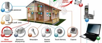
Automated control system for outdoor lighting - ASUNO "Unilight" - a software and hardware complex that allows you to monitor the condition of outdoor lighting networks, organize electricity metering and carry out equipment diagnostics. The use of modern automatic control systems makes city lighting easily controllable, economical and efficient.
- Flexible control of lighting modes
- Phase-by-phase line control
- Addressable control of each luminaire
- Individual or group dimming
- Automatic monitoring and diagnostics of the condition of equipment and lamps
- Increasing the level of operational dispatch control
- Remote energy metering
- Lighting network fault signaling
- Alarm about unauthorized connections to the lighting power supply network
- Creation of a database and reports on energy consumption
SHUNO is designed for automatic control and metering of electricity and data transmission to the control center, as well as automatic, manual or remote control of street lighting networks and lighting installations.
- Degree of protection: IP 54; IP 65
- Various cabinet options: 50A, 100A, 160A, 250A
- Dimensions: from 600x600x250
- Emergency signaling
- Operating temperature range: from -45°C to +60°C
- Delivery set: UNILIGHT control controller, Electric energy meter, Power equipment and GSM antenna
More details
- 6 outputs for controlling lighting lines
- 27 inputs for monitoring voltage, line status, door sensor and smoke
- Two RS-485 interfaces for interaction with external devices
- Built-in GSM modem. 3G support. Two SIM cards
- Remote software update
More details
The device is designed to control the luminous flux of lamps via a wireless network using cloud infrastructure via channels: GSM(3G), LoRa, NB-IoT. Control is implemented in automatic mode (according to a schedule/sensor) or manually at the command of the dispatcher, and it is also possible to monitor the state of the luminaires for the presence of accidents via feedback. The system allows the use of any types of luminaires equipped with drivers with control protocols 0/1-10 or DALI.
- Supports up to 16 independently controllable luminaires
- Temperature range from -40 to +70
- Built-in sensors: humidity, temperature, light
More details
The software is capable of managing various communication technologies (NB-IoT/ LoRa / GSM), and is able to integrate hardware solutions for street lighting control from different suppliers. In addition, the system can connect and control other sensors and actuators with an open protocol, thereby transforming the Unilight automated control system infrastructure into the SMART CITY platform.
The infrastructure of any residential, industrial or administrative facility requires the presence of outdoor lighting. The system must operate safely and smoothly. External lighting control is aimed at accomplishing this task.
Advantages of an automated lighting control system
The most optimal solution for effective lighting control is the use of fully automated control and dispatch systems for outdoor lighting (ACS).
Why is an automated system more effective than classical control methods? The heart of ASUNO is a programmable logic controller, which controls the switching of outgoing lines according to a predetermined program. The controller program stores an annual schedule, so the lighting always turns on at the right time. Data on energy consumption and accidents are transmitted to the dispatch center, so information about the state of power at the input to the substation and the value of power consumption is always available. By reducing current energy consumption relative to the norm, you can estimate the number of burnt out lamps. If the energy consumption norm is exceeded, an illegal connection to the power grid is identified. All diagnostic information is available in the dispatch center; the participation of a bypass team is not required. Thus, the accident rate is reduced due to preventive monitoring and maintenance costs are saved.
Rice. 1. Control cabinet for the city lighting system in Vladivostok
Street lighting control methods
In practice, three methods of light control are used: manual, remote and automatic.
Manual control
Switching on and off street lamps is carried out manually. Each light source or group of them is controlled by the operator directly on site.
This method is the most ancient. Since ancient times, lamplighters approached each lantern (gas or oil) and lit the pole, and later extinguished it. Even today, manual control of outdoor lights is used in the courtyards of private houses. However, in public utilities it is impossible to control the light manually due to the scale of the work, so this method is used only in emergency cases (for example, when performing repairs).
Remote control
Over time, technology developed - instead of lamplighters, employees of energy distribution networks began to manage lighting. The service workers did this remotely, turning the switch on or off. As a result of the actions, voltage is supplied to the network or, conversely, stopped.
Automatic control
Automatic control is the most advanced way to control light. Turning the light on and off is carried out through the use of sensors operating according to a specific algorithm. As a result, the lighting system operates without direct human intervention.
The transition to automatic control is caused by a change in the technological process. Voltage is supplied to consumers with the participation of locally located transformer stations. At these facilities, high-voltage voltage is converted into a voltage of the required magnitude.
There are two circumstances dictating the transition to automatic control:
- Most often, it is not economically profitable to build separate substations for street lighting. Current transformers convert voltage for all electricity consumers in a given area.
- For centralized control over turning on and off the lamps, it would be necessary to pull a separate cable to each substation, which would only increase the already high costs.
In this regard, a massive transition to automatic systems began. At the very beginning of the development of technology, the control principle was simple: devices in contact with light sensors were installed at substations.
Over time, the shortcomings of this approach became visible:
- incorrect operation due to incorrect calibration;
- lanterns often went out at night due to headlights from passing cars or even moonlight;
- if the sensor was covered with snow, mud or ice, the lamp would trigger falsely;
- sensors often failed.
Another disadvantage of light sensors is the linearity of the technology. Light is not necessarily needed even at night if there are no moving objects in the area.
In order to somehow optimize the technology, sensors began to be combined with time relays. As a result, the timer turned the lights on and off at a certain time. For example, the lighting worked from 10 pm to 4 am.
Later, astronomical relays appeared. In such devices, the program calculates the time of sunset and dawn using a certain algorithm. Based on the calculation, the lighting is controlled.
Light sensors are still used. The devices are relevant for controlling light in the event of an unexpected decrease in natural light (for example, fog).
Today, the most popular are automatic systems based on digital technologies, which combine automation and manual control.
Automatic light switching
Using sensors as introductory automata
All these are “old-fashioned” methods, but modern technologies do not stand still. Nowadays, schemes using motion or light sensors are becoming increasingly common. These devices will allow you to completely remove yourself from managing the lighting network.
The photo shows a variety of motion sensors
So:
- Light sensors are triggered when the light level drops to a certain level. Thanks to the presence of adjustment, you can set this level yourself.
- Motion sensors are triggered when there is movement in a certain sector. It also has an adjustment for the level of this movement, which will allow you to eliminate false activation from a running cat. In addition, motion sensors are equipped with customizable shutdown timers after triggering.
- Also on sale are combined motion and light sensors that are triggered in the presence of both factors. In most cases, they have the ability to adjust both parameters, as well as the shutdown delay time.
- The characteristics of sensor-based lighting machines have quite a few parameters. First of all, this is, of course, the rated current that they are capable of switching. Usually it is 6 or 10A. To switch high currents, circuits are used, which we will discuss below.
Note! To be fair, it is worth noting that you can find models with a rating of 25A. But in most cases, the price of such a photo relay is quite high, and the declared nominal parameters do not always correspond to reality.
- Since the sensors are designed for outdoor installation, we must not forget about their protection. Here it is also better to choose devices with IP 44 and higher.
- For motion sensors, a very important parameter is the viewing angle. It can vary up to 360⁰. The price also depends on its size. Therefore, if you need a narrowly focused sensor, for example, on a garden path, then you should choose products with a smaller angle. If you are planning to monitor movement on a playground or clearing, then you need a sensor with a large viewing angle.
Various light sensors
- The characteristics of a machine for lighting of this type include the rated power of the device. But usually it is extremely small and is not significant for the lighting network.
- You can also note different possibilities for adjusting light and motion sensors. The difference can reach dozens of times, but, frankly speaking, you will perform the adjustment once during installation and you will not need it again. But the timer, which is available on motion sensors and combined models, can be very useful. Usually it allows you to vary within 5 minutes, but you can find models with a longer delay.
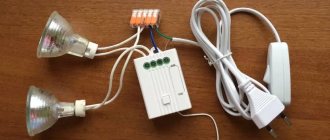
Scheme for switching on outdoor lighting using a motion sensor
Motion sensors are installed like an automatic device to illuminate a certain area. This could be a garden path, a driveway to a garage, in general, where light is needed only for a short period of time.
Motion sensor connection diagrams
- Usually the diagram of such a connection looks like this. From the group machine, power is supplied to several lines. We install a motion sensor on the required line, which works like a regular switch.
- It is also possible to install a motion sensor not after the group machine, but after the light sensor. That is, the group machine switches and provides electrical protection for the group. Then there is a light sensor, which turns on the entire group when the light level decreases. And only when the light sensor is triggered, the motion sensor starts working.
- This scheme is good if you need to ensure that part of the lighting turns on simply when it gets dark, and part of the lighting should turn on only when a person is present.
- If you need all existing outdoor lighting to turn on only when there is a person present and in the dark, then the ideal solution would be a combined light and motion sensor.
Scheme for switching on external lighting from a light sensor
We have already partially described the main uses of the light sensor above. But let's take a closer look at its connection diagram.
Light sensor connection diagram
- From our group circuit breaker in the distribution board we lay a wire to the light sensor. To switch the lighting network, we need to connect the phase wire from the machine and the phase wire going directly to the lamps. In addition, for the device to work, we need to apply zero to the correspondingly designated sensor output. You can learn more about this process in the video presented on our website.
Note! The location of the light sensor is very important. It should not be located in the lighting area of the lamps. Otherwise, when the lighting is turned on, the sensor will turn it off. Also, the installation location should not be in the shadow of trees or buildings. This may cause the lights to turn on incorrectly.
- If you use a light sensor to turn on more than 20 lamps, then, according to clause 6.3.4 of the PUE, you should install additional circuit breakers. They can be installed in the distribution board next to the input circuit breaker. But in this case, the cost of installation will increase significantly. Yes, a sensor with a high rated current will not be cheap. Therefore, another option is often used.
Scheme for switching on powerful outdoor lighting from a light sensor
But what kind of machine should we install for lighting if we need several groups to turn on at once when it gets dark? In this case, the total load can exceed 25 and 32 A. For this, a joint connection circuit between the sensor and the starter is used.
Scheme for switching on lighting from a light sensor through a starter
- With this lighting scheme, the wires of several outdoor lighting power groups are connected to the terminals of the starter of the appropriate size. But this is only in the case of using a single-phase network and when the number of groups is no more than three.
- If there are more groups or a three-phase network is used, which is more likely, then the starter is installed in front of the group circuit breakers for switching on outdoor lighting.
- The starter is controlled by a light sensor. To do this, one of the phase power wires of the group is connected to the sensor, and the output from the sensor is connected to the starter coil. This ensures control of the starter activation from the sensor.
- When the starter is triggered, voltage is supplied to all lighting groups, which allows switching quite heavy loads.
Automatic system design
The hardware of the equipment consists of the following levels:
- The top level is the control room panel. Managed by a dispatcher. The panel receives information from lower-level systems. At the top level, program parameters are adjusted or other management actions are taken.
- The lower level includes an electrical panel located in the lighting area. The boards are designed to switch the operation of lamps and control their functioning without human intervention.
The control process is carried out with the participation of a zonal controller or server equipment. The controller is used to generate a signal to connect a group of street lamps.
There are several ways to switch between upper and lower layers:
- Modem channel. Communication is carried out via telephone line. This is the most financially accessible switching method. Laying a dedicated line is quite an expensive undertaking.
- GSM channel. Street lighting can be controlled using a global positioning system or a device that can accurately determine the time of sunrise and sunset. The controller turns on 20 minutes before sunset and turns off 15 minutes before dawn. The equipment is inexpensive, but the connection itself will cost a lot of money.
- LAN channel. A method of communication where the control unit and the control center are in contact via a twisted pair cable. Communication is free, but you will have to lay a cable to each cabinet. The technology is relevant only when equipment of different levels is located close together.
- Radio channel. The equipment is expensive, communication is free. Disadvantage: instability to interference.
Automation capabilities
An automated external light control system allows you to solve a number of problems. Conventionally, they can be divided into two groups - management functions and control functions.
- Turning lights on and off.
- Programming the operation of devices based on time or sensor response.
- Phase switching on power lines.
- Forced reboot of microprocessors in the control cabinet.
- Checking the status of connection lines.
- Control of input lines.
- Monitoring the operation of contactors and output circuit breakers.
- Monitoring electricity consumption meters.
- Monitoring of unauthorized access to the cabinet.
- Checking the line status.
- Studying system faults.
- Monitoring for fires.
Street light control systems are equipped with built-in power supplies. If the power is turned off, the system can operate for at least another hour. Many systems provide not only for the transmission of data about parameter changes, but also for duplicate storage of information.
Automated lighting control systems based on solutions from Phoenix Contact
The core of the control system is the programmable controller ILC 130 ETH. The controller has a built-in real-time clock with synchronization capabilities, which allows you to control lighting line contactors according to a predetermined schedule. The developed lighting control program controls from one to 26 contactors. Moreover, the switching of each contactor is configured both according to its own separate schedule, and with the possibility of combining several contactors into a group schedule. The schedule can be adjusted from the dispatch center. Each contactor can be remotely turned on, turned off, or temporarily switched to an alternative schedule.
If it is not practical to enter an alternative schedule, you can turn it on and off using a forced command. You can also configure in advance the ability to automatically return to work according to a schedule if, during forced activation, there is no connection with the dispatch center for a specified time.
Communication with the dispatch center is carried out via an Ethernet network. For this purpose, any available technologies are used, such as fiber optic lines, 3G cellular networks or ADSL. To ensure information protection, the control system can be equipped with a firewall with VPN technology using the IPSec or OpenVPN protocols. Since dedicated communication lines are not always available, communication is most often carried out via the Internet, and data encryption with access restrictions is necessary to ensure the security of lighting objects. Ethernet communication has a number of advantages. The controllers are available for programming from the network, and there is no need to travel to the site to maintain or change the program to suit a new specification. The standard NTP protocol is used for time synchronization. The controller can connect to an exact time server on the Internet, to the control room time server, or to the time server of its local router. For the most efficient time synchronization, routers with a built-in GPS/GLONASS TC MGUARD receiver are used. They receive coordinates and exact time from satellites and transmit this data to the controller. Thus, in addition to time synchronization, it is possible to accurately link an object to the area in the GIS module of the dispatch software in automatic mode.
Rice. 2. Management system structure
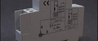
The controller has the ability to connect its own module for measuring power network parameters or electricity meters via the RS485 interface, such as “Mercury” or PSCh. As already mentioned, based on the measured energy consumption values, one can judge the number of burnt out lamps or illegal connection to the power grid. When the system is first started, the controller remembers the nominal values at full load and at complete shutdown of the various stages. During operation, the controller can be given a command to overwrite these parameters. A monitoring relay is optionally installed on each lighting line, providing fault diagnosis across the entire cascade.
Rice. 3. Communication system structure
To ensure continuous operation of the system, an uninterruptible power supply unit is installed in the control cabinet, ensuring autonomous operation of the controller for up to 48 hours or more, depending on the battery/accumulator. If there is a backup input, the control system can also perform the functions of an ATS. If there is no voltage at the main input, the system will switch to the backup one.
Rice. 4. Architecture of the dispatch system
Control cabinet
The external lighting control cabinet (ECC) is the central link of the system, where all the circuits that distribute loads and control the lighting process are concentrated. The cabinet protects the photo relay from short circuits and voltage surges.
The diagram shows the operation of the control box, where 1 is the electric meter, 2 is the lock, 3 is the protective barrier, 4 is the cabinet.
The main task of the cabinet is to control the operation of the relay based on the time of day, control using the remote control and adjust the brightness of the light after connecting the relay.
Cabinets operate in the following management modes:
- Local control (regular timer, astro-timer or other determining device).
- Cascade voltage control system 220 V/50 Hz. Control is carried out via a special signal conductor from another cabinet or remote control.
- Local control.
The selection of modes is made with the participation of existing controls. The cabinets have separate control of night lighting (three single-phase lines) and additional night lighting (three single-phase lines in 100 A electrical panels and six in 250 A panels). The cabinets are equipped with internal lighting using an incandescent light bulb of 40 - 60 W.
If financial capabilities allow laying a cable to each street lamp with a relay, one of the cabinets is placed inside the building, and the second at the entrance to the site. However, the shields will operate simultaneously, as a result of which each unit will consume electricity as a full-fledged cable channel.
The following scheme is recommended: the first cabinet is placed at the gate, connecting lamps with motion sensors and photo relays to its controller. The second cabinet is installed inside the house. It will provide remote control (using a remote control).
The following system would be optimal: the first cabinet is installed at the gate, and lights with motion sensors with photo relays located along the path are connected to its controller. The second cabinet is placed directly inside the room - remote control will be carried out from here. The scheme is simple: certain lamps are connected to the channel that goes to the control unit, and a signal is sent from the remote control. The panel allows you to transmit commands to automatically turn off the current around the perimeter of the site.
What types of devices are there for automatic backlighting?
The variety of modern equipment designed for automatic connection of light is quite extensive. But among the entire range, the following models are the most popular:
- twilight relays or photo relays. Such devices operate when the level of illumination on the street drops to a certain level, independently turning on the backlight;
- lamps equipped with motion sensors. These types of devices work effectively near structures - garage doors, central and back entrances to the house, veranda, etc. Activation occurs when movement appears within range;
Light with motion sensor
Astronomical relay
- astronomical relay. This type of equipment is used to solve certain problems. A special feature of such relays is that they are programmed by coordinates. There is no need to install the sensor itself on the plot. This device is capable of independently calculating the time of sunset and dawn, as well as the time of year, thanks to which it can effectively turn on the light automatically at the right time;
- relays with a delay function for turning off the light. Such devices can be controlled by push-button switches and can also be turned off after a programmed time.
Any type of equipment that operates in automatic backlight mode can be easily installed with your own hands. To connect here you only need the diagram supplied by the manufacturer.
Control systems
Luminaires with HID bulbs are controlled in the traditional way. For this purpose, ballast and ballast resistance are used. The technology is based on setting a power limit for lighting equipment. Limitation - face value.
Magnetic or induction ballast
Magnetic ballasts (induction) work on the following principle: the current acts as a ignition element for a gas-discharge light bulb. Induction ballast is necessary to limit the power of the light source due to inductive resistance.
Disadvantage of magnetic ballasts: phase shift between voltage and electric current, which causes the luminous flux to change.
A so-called pulse ignition device is sometimes used to start the reaction. The picture below shows a circuit using an IZU.
Electronic ballast
Low frequency or high frequency electronic ballasts qualify as traditional control type. They do not have a starter. Thanks to electronic ballast, the efficiency of the luminaire is improved, as the weight of the device is reduced and electricity consumption is reduced. Such devices are characterized by low noise. The disadvantage of electronic ballasts is the distortion of harmonics, which deteriorates the quality of radio waves. The figure below shows the connection diagram for the electromagnetic ballast.
Through the use of electronic ballasts, it is possible to achieve high-quality ignition of the light bulb and maintain a given voltage level. The device is usually equipped with remote controls.
The disadvantage of electronic ballasts is that the lamps and photocells are susceptible to contamination, which reduces the responsiveness of the device. There may be difficulties with calibrating the sensor.