How to determine the torque of an electric motor
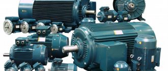
In this article we will cover the topic of mechanical and electrical characteristics of electric motors. Using the example of an asynchronous motor, we will consider such parameters as power, work, efficiency, cosine phi, torque, angular speed, linear speed and frequency. All these characteristics are important when designing equipment in which electric motors serve as drives. Today, asynchronous electric motors are especially widespread in industry, so we will focus on their characteristics. For example, consider AIR80V2U3. Rated mechanical power of an asynchronous electric motor
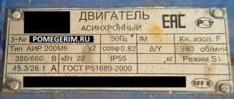
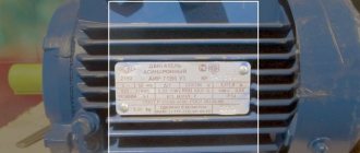
The nameplate (on the nameplate) of the electric motor always indicates the rated mechanical power on the shaft of this motor. This is not the electrical power that this electric motor consumes from the network.
So, for example, for an AIR80V2U3 engine, a rating of 2200 watts corresponds precisely to the mechanical power on the shaft. That is, in optimal operating mode, this engine is capable of performing mechanical work of 2200 joules every second. Let's denote this power as P1 = 2200 W.
Rated active electrical power of an asynchronous electric motor
To determine the rated active electrical power of an asynchronous electric motor based on nameplate data, it is necessary to take into account the efficiency. So, for this electric motor the efficiency is 83%.
What does it mean? This means that only part of the active power supplied from the network to the stator windings of the motor, and irreversibly consumed by the motor, is converted into mechanical power on the shaft. Active power is equal to P = P1/efficiency. For our example, from the presented nameplate we see that P1 = 2200, efficiency = 83%. This means P = 2200/0.83 = 2650 W.
Rated apparent electrical power of an asynchronous electric motor
The total electrical power supplied to the stator of an electric motor from the network is always greater than the mechanical power on the shaft and greater than the active power irretrievably consumed by the electric motor.
To find the total power, it is enough to divide the active power by the cosine phi. Thus, the total power is S = P/Cosφ. For our example, P = 2650 W, Cosφ = 0.87. Therefore, the total power S = 2650/0.87 = 3046 VA.
Rated reactive electric power of an asynchronous electric motor
Part of the total power supplied to the stator windings of an asynchronous electric motor is returned to the network. This is the reactive power Q.
Reactive power is related to apparent power via sinφ, and is related to active and apparent power via square root. For our example:
Q = √( 3046 2 – 2650 2 ) = 1502 VAR
Reactive power Q is measured in VAR - in reactive volt-amperes.
Now let's look at the mechanical characteristics of our asynchronous motor: rated operating torque on the shaft, angular speed, linear speed, rotor speed and its relationship with the motor supply frequency.
Rotor speed of an asynchronous electric motor
On the nameplate we see that when powered by alternating current with a frequency of 50 Hz, the motor rotor makes 2870 revolutions per minute at rated load, let’s denote this frequency as n1.
What does it mean? Since the magnetic field in the stator windings is created by an alternating current with a frequency of 50 Hz, then for a motor with one pair of poles (which is AIR80V2U3), the “rotation” frequency of the magnetic field, the synchronous frequency n, turns out to be equal to 3000 revolutions per minute, which is identical to 50 revolutions per second. But since the motor is asynchronous, the rotor rotates with a lag by the slip amount s.
The value of s can be determined by dividing the difference between the synchronous and asynchronous frequencies by the synchronous frequency, and expressing this value as a percentage:
s = ( ( n – n1 )/ n) *100%
For our example, s = ( (3000 – 2870)/3000 ) *100% = 4.3%.
Angular speed of asynchronous motor
Angular velocity ω is expressed in radians per second. To determine the angular velocity, it is enough to convert the rotor speed n1 into revolutions per second (f), and multiply by 2 Pi, since one full revolution is 2 Pi or 2 * 3.14159 radians. For the AIR80V2U3 engine, the asynchronous frequency n1 is 2870 rpm, which corresponds to 2870/60 = 47.833 rpm.
Multiplying by 2 Pi, we have: 47.833*2*3.14159 = 300.543 rad/s. You can convert it to degrees; to do this, substitute 360 degrees instead of 2 Pi, then for our example you get 360 * 47.833 = 17220 degrees per second. However, such calculations are usually carried out in radians per second. Therefore, the angular velocity is ω = 2*Pi*f, where f = n1/60.
Linear speed of an asynchronous electric motor
Linear speed v refers to equipment where an asynchronous motor is installed as a drive. So, if a pulley or, say, an emery disk of known radius R is installed on the motor shaft, then the linear speed of a point on the edge of the pulley or disk can be found by the formula:
Rated torque of asynchronous motor
Each asynchronous electric motor is characterized by a rated torque Mn. Torque M is related to mechanical power P1 through angular velocity as follows:
The torque or moment of force acting at a certain distance from the center of rotation is conserved for the engine, and as the radius increases, the force decreases, and the smaller the radius, the greater the force, because:
So, the larger the radius of the pulley, the less force acts on its edge, and the greatest force acts directly on the electric motor shaft.
For the AIR80V2U3 engine given as an example, the power P1 is equal to 2200 W, and the frequency n1 is equal to 2870 rpm or f = 47.833 rpm. Therefore, the angular velocity is 2*Pi*f, that is, 300.543 rad/s, and the nominal torque Mn is equal to P1/(2*Pi*f). Mn = 2200/(2*3.14159*47.833) = 7.32 N*m.
Thus, based on the data indicated on the nameplate of the asynchronous electric motor, you can find all its main electrical and mechanical parameters.
We hope that this article helped you understand how angular velocity, frequency, torque, active, net and apparent power, as well as the efficiency of an electric motor, are related to each other.
This calculator allows you to convert power and torque and back for a given angular velocity
Basic parameters of the electric motor
- Motor power
- Rated speed
- Efficiency
- Motor torque
- Rotor moment of inertia
- Rated voltage
- Electrical time constant
Motor power
Motor power is the useful mechanical power at the motor shaft.
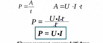
Mechanical power
Power is a physical quantity that shows how much work a mechanism does per unit of time.
- where P
– power,
W
, - A
– work,
J
, - t
—time,
s
Work is a scalar physical quantity equal to the product of the projection of force and direction F
and the path
s
traversed by the point of application of the force.
- where s
– distance,
m
For rotational movement
- where θ – angle, rad
- where ω – angular frequency, rad/s
,
In this way, you can calculate the value of mechanical power on the shaft of a rotating electric motor
Reference: Nominal value is the value of a parameter of an electrical product (device), specified by the manufacturer, at which it should operate, which is the initial value for calculating deviations.
Rotation frequency
- where n
is the rotation speed of the electric motor,
rpm
Rotor moment of inertia
The moment of inertia is a scalar physical quantity, which is a measure of the inertia of a body in rotational motion around an axis, equal to the sum of the products of the masses of material points by the squares of their distances from the axis
- where J
is the moment of inertia,
kg∙m2
, - m
—mass,
kg
Reference: In the English system of measures, the moment of inertia is measured in ounce-force-inch (oz∙in∙s2) 1 oz∙in∙s2 = 0.007062 kg∙m2 (kg∙m2)
The moment of inertia is related to the moment of force by the following relation
- where ε – angular acceleration, s-2
Reference: Determination of the moment of inertia of the rotating part of the electric motor is described in GOST 11828-86
Electric motor efficiency
The efficiency of an electric motor is a characteristic of the machine’s efficiency in converting electrical energy into mechanical energy.
- where η is the efficiency of the electric motor,
- P1
- supplied power (electric),
W
, - P2
- useful power (mechanical),
W
- Wherein
losses in electric motors
- due to:
- electrical losses - in the form of heat as a result of heating current-carrying conductors;
- magnetic losses - losses due to magnetization reversal of the core: losses due to eddy currents, hysteresis and magnetic aftereffects;
- mechanical losses - friction losses in bearings, ventilation, brushes (if any);
- additional losses - losses caused by higher harmonics of magnetic fields arising due to the gear structure of the stator, rotor and the presence of higher harmonics of the magnetomotive force of the windings.
Electric motor efficiency can vary from 10 to 99% depending on the type and design.
The International Electrotechnical Commission defines the efficiency requirements for electric motors. According to the IEC 60034-31:2010 standard, four efficiency classes are defined for synchronous and asynchronous motors: IE1, IE2, IE3 and IE4.
Rated voltage
Rated voltage is the voltage for which the network or equipment is designed and to which their operating characteristics are related.
Electrical time constant
The electrical time constant is the time, counted from the moment a direct voltage is applied to the electric motor, during which the current reaches a level of 63.21% (1-1/e) of its final value.
- where is the time constant, s
Motor torque
Torque (synonyms: torque, torque, moment of force) is a vector physical quantity equal to the product of the radius of the vector drawn from the axis of rotation to the point of application of the force and the vector of this force.
- where M
– torque,
Nm
; - F
– force,
N
; - r
– radius vector,
m
Help: Nominal torque Mnom, Nm, is determined by the formula
- where Pnom
is the rated power of the engine,
W
, - nnom
- rated speed,
min-1
Initial starting torque is the torque of the electric motor at start-up.
Help: In the English system of measures, force is measured in ounce-force (oz, ozf, ounce-force) or pound-force (lb, lbf, pound-force) 1 oz = 1/16 lb = 0.2780139 N (N) 1 lb = 4.448222 N (N)
torque is measured in ounce-force per inch (oz∙in) or pound-force per inch (lb∙in)
1 oz∙in = 0.007062 Nm (Nm) 1 lb∙in = 0.112985 Nm (Nm)
Mechanical characteristics
The mechanical characteristic of the engine is a graphically expressed dependence of the shaft speed on the electromagnetic torque at a constant supply voltage.
Selecting an electric motor based on torque
To make the choice required to perform certain tasks of an electric motor, almost all of its characteristics are taken into account, starting from power indicators and ending with weight and size parameters. Each of the elements is important in its own way in solving the nuances. Torque is no less important. Due to the fact that the torsional torque is directly related to the revolutions in the ratio: the higher the revolutions themselves, the less the torque will be, the choice of an electric motor will be based on the following nuances:
- from speed requirements. In this case, it will be more useful to select a motor with low torque for those operating with low forces and at high speed, and with medium or high starting torques for those operating in heavy duty modes. At low speeds;
- according to starting voltages. Here the primary force is taken into account, for example, to control an elevator, motors with high starting torque should be selected, capable of lifting large loads from the start. Although, many articles about electric motors also recommend using soft starters that can protect against unwanted overloads.
It is worth remembering that the choice is not made according to one of the indicators, even when oriented relative to torque, because each of the indicators is oriented according to the operating predisposition of the electrical drive device and its workloads in statistical and dynamic operating conditions set by the enterprise itself.
Still have questions? ENERGOPUSK specialists will answer your questions: 8-800-700-11-54
(8-18, Mon-Tue)
What is electric motor torque
One of the important parameters of an electric motor, which is also important when choosing it, is torque. This value is determined by the product of the force applied to the lever arm and depends solely on the degree of load. If in internal combustion engines this load is set by the crankshaft, then asynchronous electric motors receive torque from excitation currents. In this case, the magnitude of this moment will depend on the speed of a device called a rotor rotating in the magnetic field of the stator. Depending on the period and method of determination, torque is divided into:
- static (starting) – minimum idle torque;
- intermediate – develops a value during engine operation from 0 speed to the maximum value in the rated voltage;
- maximum – developing during engine operation;
- nominal – corresponds to the nominal values of power and speed.
To calculate the value of torque, defined in “kgm” (kilogram per meter) or “Nm” (newton per meter), many electrical manuals offer special formulas that take into account, in addition to the main action of the rotating magnetic field, a number of various factors, for example:
- mains voltage;
- the value of inductive and active resistance;
- dependence on increased slip.
But, an increase in slip does not always bring a high moment. Often, when critical values are reached, a sharp decrease is observed. This phenomenon is referred to as an overturning moment. One of the devices that stabilizes the speed of rotation of the rotor, and therefore the magnitude of the torsional torque, is a frequency converter, the use of which is now very common in all areas where the success of performing multiple production tasks depends on the control of engine operation.
Torque of asynchronous motor
to contents
The rotor and stator poles are acted upon by electromagnetic torques that are equal in magnitude and directed in opposite directions. The power required to rotate the stator poles at synchronous frequency is
,
where is the angular velocity.
The mechanical power developed by the rotor is
where is the angular velocity of the rotor.
Power difference
where РЭ2 are electrical losses in the rotor winding; m2 is the number of phases of the rotor winding; R2 is the active resistance of the rotor winding; I2 is the rotor current. where
(7).
Torque, taking into account (6),
.
where , CT is the transformation ratio of the motor with a locked rotor.
,
where U1 is the network voltage.
(8).
where is a constant.
In Fig. Figure 5 shows the dependence of the electromagnetic torque on slip in the form of a solid line.
Rice. 5
Let the actuator driven by this engine create a counteracting braking torque M2.
In Fig. 5 there are two points for which the equality Mem = M2
;
these are points a
and
b
.
At point a
the engine runs stably.
If the engine, under the influence of any reason, reduces the rotation speed, then its slip will increase, and along with it the torque will increase. Thanks to this, the engine speed will increase, and the equilibrium Mem = M2
.
At point b ,
engine operation cannot be stable: a random deviation in the rotation speed will either stop the engine or cause it to go to point
a
.
Consequently, the entire ascending branch of the characteristic is an area of stable operation of the engine, and the entire descending part is an area of unstable operation. Point b
, corresponding to the maximum torque, separates the areas of stable and unstable operation.
The maximum value of the torque corresponds to the critical slip Sk
.
Slip S = 1
corresponds to the starting torque.
If the value of the counteracting braking torque M2
is greater than the starting MP, the engine will not start when turned on and will remain motionless.
We find the maximum moment as follows. First, we determine the value of the critical slip at which the Mem
will be maximum.
To do this, we equate the first derivative of the sliding function S
from expression (8) to zero. where
. (9)
Substituting the value of the critical slip into formula (8), we obtain
. (10)
From formulas (8), (9), (10) it is clear:
- the maximum torque value does not depend on the active resistance of the rotor circuit;
- with an increase in the active resistance of the rotor circuit, the maximum torque, without changing in value, shifts to the region of large slips (see curve 1, Fig. 12.5);
- torque is proportional to the square of the network voltage.
The mechanical characteristic of an asynchronous motor is the dependence of the motor speed on the torque on the shaft n2 = f (M2). The mechanical characteristic is obtained under the condition U1 - const, f1 - const. The mechanical characteristic of the engine is the dependence of torque on slip, plotted on a different scale. In Fig. 6 shows a typical mechanical characteristic of an asynchronous motor.
| Rice. 6 | With increasing load, the torque on the shaft increases to a certain maximum value, and the rotation speed decreases. As a rule, an asynchronous motor has a starting torque less than the maximum. This is explained by the fact that in the starting mode, when n2 = 0 and S = 1, the asynchronous motor is in a mode similar to a short circuit in a transformer. The magnetic field of the rotor is directed opposite to the magnetic field of the stator. |
The resulting, or main, magnetic flux in the air gap of the machine in starting mode, as well as the emf in the stator and rotor E1 and E2, are significantly reduced.
This leads to a decrease in the starting torque of the engine and a sharp increase in the starting current. to contents
Did you know,
that according to relativistic mythology, “gravitational lensing is a physical phenomenon associated with the deflection of light rays in a gravitational field. Gravitational lenses explain the formation of multiple images of the same astronomical object (quasars, galaxies), when another galaxy or cluster of galaxies (the lens itself) falls on the line of sight from the source to the observer. Some images appear to enhance the brightness of the original source." (Relativists give examples of distortion of images of galaxies as confirmation of GTR - the effect of gravity on light) At the same time, they forget that the field of action of the GTR effect is small angles near the surface of stars, where in fact this effect is not observed (eclipsing binaries). The difference in the scale of the phenomena of real distortion of images of galaxies and the mythical deviation near stars is 1011 times. Let me give you an analogy. You can talk about the effect of surface tension on the shape of droplets, but you can't seriously talk about the force of surface tension as a cause of ocean tides. Ethereal physics finds an answer to the observed phenomenon of distortion of galaxy images. This is the result of heating the ether near galaxies, changing its density and, consequently, changing the speed of light at galactic distances due to the refraction of light in the ether of different densities. Confirmation of the thermal nature of the distortion of galaxy images is the direct connection of this distortion with the radio emission of space, that is, the ether in this place, the shift of the CMB spectrum (cosmic microwave radiation) in a given direction to the high-frequency region. Read more in the FAQ on ethereal physics.
Selecting an electric motor based on torque
To make the choice required to perform certain tasks of an electric motor, almost all of its characteristics are taken into account, starting from power indicators and ending with weight and size parameters. Each of the elements is important in its own way in solving the nuances. Torque is no less important. Due to the fact that the torsional torque is directly related to the revolutions in the ratio: the higher the revolutions themselves, the less the torque will be, the choice of an electric motor will be based on the following nuances:
- from speed requirements. In this case, it will be more useful to select a motor with low torque for those operating with low forces and at high speed, and with medium or high starting torques for those operating in heavy duty modes. At low speeds;
- according to starting voltages. Here the primary force is taken into account, for example, to control an elevator, motors with high starting torque should be selected, capable of lifting large loads from the start. Although, many articles about electric motors also recommend using soft starters that can protect against unwanted overloads.
Calculation of electric motor power factor
Online calculation of power factor (cosφ) of an electric motor
Calculation of cosφ (cosine phi) of the engine is carried out using the following formula:
- P - Rated power of the electric motor (taken from the motor’s passport data or determined by calculation);
- U - Rated voltage (voltage to which the electric motor is connected);
- I - Rated current of the electric motor (taken from the passport data of the electric motor , and in their absence is determined by calculation);
- η - Efficiency factor - the ratio of the electrical power consumed by the electric motor from the network to the mechanical power on the motor shaft (taken from 0.7 to 0.85 depending on the power of the electric motor);
What is the maximum torque and how can it be increased?
Engine power is its most important indicator. Both in terms of operation and in terms of calculating taxes on cars. Torque is often confused with power or overlooked when evaluating a car's performance. Many people simplify the car, believing that a large amount of horsepower is the main advantage of any engine. However, torque is a more important indicator. Especially if the car is not intended to be used as a sports car.
What is torque
Torque is the unit of force that is required to turn the crankshaft of an internal combustion engine. This is not “horsepower,” which is what power is supposed to be.
The internal combustion engine produces kinetic energy, thus rotating the crankshaft. The engine power indicator (pressure force) depends on the rate of fuel combustion. Torque is the result of a force acting on a lever. This force in physics is calculated in newtons. The length of the crankshaft arm is calculated in meters. Therefore, the designation for torque is newton meter.
Technically, torque is the force that must be exerted by the engine to accelerate and move the car. In this case, the force exerted on the piston is proportional to the engine volume.
The flywheel is one of the most important parts, which must transmit torque through the gearbox from the engine to the gearbox, from the starter to the crankshaft, and from the crankshaft to the pressure plate. Actually, torque is the result of pressure on the connecting rod.
Torque theme
The leading indicator by which the capabilities and applicability of a motor are judged is ENGINE POWER. Only then comes its efficiency, service life, weight and size indicators, etc.
Power, in turn, consists of the product of two main parameters:
— frequency (speed) of rotation of the motor shaft; — torque on this shaft;
The higher the value of each of these parameters, the greater the motor power. Let's consider the possibility of increasing engine power while keeping the volume of the working chambers constant. Therefore, increasing power without increasing the working liter volume is possible in only two ways:
– increasing the shaft rotation speed and the speed of movement of the main working body;
— increasing the value of torque on the motor shaft;
Let's consider the prospects for increasing each of these parameters:
Is it possible to raise the shaft rotation speed higher and higher? No, it’s not possible - and in general, for most power consumers the value of drive revolutions should be small - for a car in the city and in the starting cycle it is hundreds, or even tens of revolutions per minute, for propellers of large and small ships only a slightly higher value is needed . Even for airplane propellers, this value should not exceed 1000-1200 rpm, and for helicopters this value is noticeably lower... But modern piston engines begin to develop more or less acceptable power at rpm from 1500 rpm. Those. for such motors, complex, expensive and heavy gearboxes or variators have to be installed as intermediaries between the wheels-screws and the motors... But if, to increase power, we decide to increase the speed of the motor shaft, then the gearboxes will require even more complex and heavy ones, with a large number of gear stages . Those. – increasing power by increasing the number of shaft revolutions is a very ineffective way. Moreover, piston engines with a crank mechanism and a complex gas distribution mechanism, purely due to design features, cannot produce revolutions above 7-8 thousand per minute. The Wankel engine is noticeably more powerful, since its operating speeds are slightly higher - up to 10-12 thousand revolutions
There is, however, the possibility of installing a desmodromic mechanism for driving the intake-exhaust valves. This mechanism allows you to significantly increase the speed of the piston engine. But it is very complex and expensive. Therefore, it is only used in exotic equipment, such as Formula 1 sports cars or Ducati motorcycles.
Therefore, to increase engine power, another way is more profitable and effective - the way to increase the torque value. In engines, torque is the most important dynamic indicator and characterizes the traction capabilities of the engine.
But first, let’s briefly analyze and remember the very basic concept - what torque is.
Briefly, this physical concept can be defined as follows: torque (moment of force) is the rotating force that is created by the main working part of the engine and transmits it to the engine shaft.
You can imagine the essence of the concept of torque using the example of a conventional lever in the form of a wrench. If we put a wrench on a tightly tightened nut, and in order to tear it out of place, we forcefully press the handle of the wrench, then a torque (Mkr) will begin to act on the nut. Torque is equal to the force applied to the lever - the handle of the wrench - multiplied by the length of the force arm. In numbers, this will be described as follows: if a 10-kilogram load is suspended on the handle of a key one meter long, then a torque of 10 kg•m will act on the nut. In the SI measurement system, this indicator (multiplied by the value of the acceleration of gravity - 9.81 m/s2) will be equal to 98.1 N•m.
From this simple formula describing the mechanics of torque, the following conclusion comes: more torque can be obtained in two ways - either by increasing the length of the lever, or by increasing the weight of the load.
In an engine, torque is the product of the pressure forces of the working gases on the useful surface of the main working body, on the application arm. In cases with piston engines, this arm of application is equal to the radius of the crankshaft crank, in cases with Wankel engines it is the arm between the center of the rotor and the axis of the eccentric shaft, and in the case of a perfect rotary engine it is the arm from the center of rotation of the shaft to the middle of the working rotor blade. (RICE.)
In the most common piston engines today, torque occurs due to the combustion of the working mixture, which, expanding with high pressure, pushes the piston down. The piston, in turn, presses through the connecting rod onto the “elbow” of the crankshaft. Although the arm length is not indicated in the description of engine characteristics, this can be determined by the piston stroke (which is twice the crank radius). In the force that affects the lever arm and creates torque, the forces of friction and inertia should also be taken into account.
An approximate calculation of the torque of a piston engine goes like this. The working gases from the combustion of the fuel-air mixture press on the piston, the piston transmits pressure to the connecting rod, and the connecting rod transmits its downward movement to the crank mechanism. When the piston pushes the connecting rod with a force of 200 kg onto a shoulder of 5 cm, a torque of 10 kg•s, or 98.1 N•m, occurs. But a piston engine with a crank mechanism has one very serious drawback: it creates torque for a very short period of time in the operating cycle. A four-stroke engine develops working force only one working stroke out of four, and a two-stroke engine develops only every second stroke. During non-working strokes, the crankshaft and piston group rotate due to the inertia of the massive moving parts of the engine. That is, the distribution graph of the application of driving force to the circle of rotation will look like this..... (see torque graphs three paragraphs below)
But there is another very important aspect here. You should not think that the torque force is fully and actively working throughout the entire working stroke period. In fact, even during the actual power stroke, the torque force is not entirely complete and does not reflect the full power of the pressure force of the working gases on the piston. Those. The torque of a piston motor is related to the force of pressure of the expansion working gases on the piston in a not entirely direct and completely ineffective manner. This is due to the congenital and ineradicable defects of the intermediary between the rectilinear movement of the piston and the rotational movement of the shaft - the crank - connecting rod mechanism. Moreover, they manifest themselves in all their glory both in piston engines and in Wankel rotary engines.
Let's consider the kinematics of the crank mechanism (CPM) of a piston engine.
When the gas pressure at the first stage of fuel combustion is maximum, because At this time, the volume of the combustion chamber is minimal, and the work done by the gases is also greatest, then at this moment the torque on the motor shaft from the work of such gases is zero. Because the piston in this phase of the crankshaft operation is at top dead center and the arm of the crank lever is equal to zero. The entire kinematics of the engine (if it is a single-cylinder engine) moves only under the influence of the inertial forces of the mass of the moving parts of the piston and crank group of the engine. It is for this purpose that flywheels are installed on piston engines in order to increase the inertia of this part of the engine parts. Those. At this stage of the piston engine operation, the long centerlines of the crank arm and connecting rod line up in one straight line, which is parallel to the force vector of the expanding gases. Therefore, all the force of these gases is currently spent on deformation of the structural elements of the piston and crank group, and the useful work of the expansion gases is completely absent at this moment.
Further, under the influence of rotational inertia, the engine shaft rotates, and the movement of the crank leads to a gradual increase in the arm, which perceives the torque, i.e. the magnitude of the useful force of the expanding gases increases. The amount of increase in the value of the crank arm gradually increases to an angular distance of 60 degrees. from the top dead center position. (FIG.) It is in this position that the most efficient operation of the crankshaft is possible, but the time for obtaining the maximum possible torque (torque) is already lost, because as the angular movement downwards of the upper point of the crank arm, both the piston and the pressure of the working gases move downwards combustion chamber drops significantly... That is, the force of expansion gases at the moment of highest efficiency is no longer as great as at top dead center.
Further, the engine shaft with the crank continues to rotate and the projection of the crank arm in relation to the force vector of the expanding gases begins to decrease again... Moreover, as the piston moves down and the volume of expansion of the combustion chamber further increases, the gas pressure in it drops, and therefore the pressure force also drops of these gases onto the piston.
Consequently, on the gas expansion line and the angular path of the crank arm after it reaches a position of 60 degrees. from top dead center, the torque value drops sharply, as this is caused by the combination of two processes - a drop in the pressure of the working gases driving the piston and a sharp decrease in the crank arm that perceives the force of this pressure. At the bottom dead center, the longitudinal axes of the connecting rod and the crank arm again line up in one line, and the pressure of the working gases again senselessly wastes its already small force only on the senseless deformation of the motor elements, and the moving parts of the motor continue to rotate only under the influence of the inertia of their masses. In fact, the crankshaft produces torque on the engine shaft only in fractional, successive pulsations - a series of numerous, but short-term shocks.
All motorists feel all the delights of this particular mode of operation of a piston engine with a crankshaft, especially in moments when it is necessary from a certain average speed, if you are driving in top gear and losing the inertia of movement, to suddenly accelerate sharply - that is, to remove a powerful torque force from the engine. If you don’t switch to a lower gear, just suddenly try to increase the engine speed in the previous gear and press the gas pedal, then you won’t get a powerful traction force, but only a breathless rattling and vibration of the engine, ready to stall... This is precisely the ineffective mode of operation of the crankshaft. -a, which is not able to effectively remove torque at low shaft speeds. In this case, you have to switch to lower gear and sharply press the gas pedal to increase the engine speed, thereby providing a large number of “power pushes” of the crankshaft per unit time and increasing the traction force. But electric motors, which convert the working power of electromagnetic forces in their windings into simple rotational motion without any ineffective intermediary mechanisms, do not suffer from such a disease. That is why many motorists watch with envy how easily and powerfully bulky and heavy trolleybuses take off from traffic lights, overtaking light and seemingly powerful passenger cars in the starting impulse. The same can be said about the starting impulse of hybrid cars, where the starting impulse (torque at the start) is provided by the electric motor.
So - CVS is an inevitable and serious defect of piston engines, which sharply reduces their efficiency, increases their bulkiness, increases the price and reduces reliability. Therefore, for at least a hundred years, work has been going on, as yet unsuccessful, to create connecting rodless circuits for piston engines. The work has been going on for a hundred years, but no serious return has yet been seen, since the piston engine circuit itself has long exhausted its potential for fundamental improvement. That is why, for almost the entire history of technology, attempts have been made to create a more efficient and engineering-perfect motor design without the use of reciprocating pistons. The line of creating rotary machines with rotational movement of the main working element is precisely this direction.
Rotary engines
The most famous engine using the principle of continuous rotation of the main working body is the gas turbine. But the gas turbine does not have a hermetically sealed combustion chamber and this is its main drawback, which manifests itself in low efficiency and high fuel consumption. Unlike piston engines - “volumetric expansion” engines, turbines are “flowing” power machines. Therefore, we will not talk about these types of power machines, especially since turbines with torque are quite decent (though only at high rotation speeds of their rotor-impeller). Now let's talk about rotary engines with locked combustion chambers.
The only rotary engine produced on an industrial scale today is the Wankel engine - a rotary engine with planetary motion of the main working element. As I already wrote, this type of engine has one undeniable advantage - it is the simplest type of structure in terms of the number of parts. But at the same time, it has considerable innate disadvantages that are inevitable for this type of organization of internal kinematics. And one of the main disadvantages is the presence of a KShM. Don’t be surprised: how is it that it’s a rotary engine but has a crank mechanism? But that’s how it is. True, the Wankel engine does not have a full-fledged crankshaft, like its piston competitors, but only a fragment of it. But this fragment contains all the main shortcomings and defects of the classic KShM, which play into such a difficult fate of this type of engine. Therefore, Wankel engines could not displace their piston competitors - because they did not have an advantage in the main thing: there was no simple and low-cost scheme for converting the pressure of working gases into rotation of the working shaft. That is, the Wankel rotary engine only partially moved away from the reciprocating movement of the pistons, but was never able to achieve a pure and simple rotational movement of the main working element, so in its design it was necessary to use a crank mechanism, with all its shortcomings and losses. (FIG.) Accordingly, one must understand that the planetary rotational movement of the rotor center around the geometric center of the working chamber and around the shaft axis is an intermediate version of the device, between two diametrically opposed types of organizing the movement of the main working elements of different types of engines: reciprocating and simple rotational movement .
Let's consider how the crank mechanism works and manifests itself in the Wankel engine, which creates the most important thing in the engine - torque.
In a rotary motor with planetary motion of the main working element, gas pressure is transmitted to the edge of the rotating triangular rotor. Gases push this edge and impart rotational and translational motion to the rotor. The rotor, which is movably mounted on an eccentric shaft, rotating around its geometric center, simultaneously performs a translational - annular movement along the cavity of the working chamber. During this movement, the geometric center of the rotor describes an even circle around the center of the combustion chamber, which coincides with the main axis of the eccentric shaft. It is extremely difficult to mechanically convert the rotational movement of the rotor around its axis into shaft rotation, so it remains to remove the useful force from the planetary, ring-shaped rotation of the rotor center around the center of the working chamber. This is exactly what the eccentric shaft does, but if we take a closer look at its design, we will find that it contains the so familiar and so ineffective crank. At the same time, the shortcomings of the operation of this mechanism in the Wankel engine are, as it were, hidden in the unusualness of its design, and therefore are not immediately apparent, although all the defects and flaws in the operation of this mechanism in a rotary motor with planetary rotation of the main element are manifested “in full.”
So, the expansion of working gases in a Wankel engine occurs only in one zone of its combustion chamber, the shape of which is called epitrochoid. (FIG.) Consequently, the beginning of the expansion stroke and its completion will occur in constantly identical geometric positions. Therefore, the total force vector that will impart planetary, rotational and translational motion to the rotor will always work in one direction. But the lever arm, which is possessed by a disk eccentrically mounted on the motor shaft, which will translate the translational movement of the rotor into rotation of this shaft, will change all the time according to the law of a sinusoid. That is, there will be two geometric points when the projection of the lever arm in relation to the direction of the vector of the acting force will be equal to zero. (FIG.) There will also be two points when the projection of the lever arm in relation to the force vector will be maximum, and at all other points the projection of this arm will be different in value, changing according to the law of a sinusoid. Everything is exactly the same as in the KShM-e piston engine. That is why the Wankel engine, designed with one rotor section, has an extremely unsatisfactory torque diagram - even worse than that of a piston engine. After all, the stroke length of a Wankel engine is shorter, so the jerks in increasing and decreasing torque intensity are even greater. But to this disadvantage is added the possibility of having a negative torque in a small area of rotation of the rotor, i.e. a moment that works against the main rotation of the rotor... There is definitely no such stage in the torque diagram in piston engines. It is for this reason that single-section Wankel motors with one rotor have a very poor torque diagram and require massive flywheels to achieve acceptable performance. In the above diagram from the old book “Marine Rotary Engines,” you can clearly see how in the first (top graph) the line of the torque value in a single-section Wankel engine part of the time falls into the field of negative values. Those. for some time the force of the working gases rotates the rotor in the opposite direction... accordingly, the torque mode of such an engine is very poor.
The eccentric shaft makes three revolutions per revolution of the rotor, and this ratio is set by a specially selected gear ratio that determines the movement of the rotor in relation to the body and the diameter of the eccentric disks of the main shaft. Since the rotor has three faces, one revolution of the shaft occurs for exactly one working stroke, which each face of the rotor makes, that is, a rotation of the shaft with the passage of two dead points of the eccentric shaft crank will be carried out for each working stroke. Those. For each working stroke of the rotor edge and shaft revolution, there will be two points when the crank arm is equal to zero and the torque is also equal to zero. At this moment, the rotor and shaft rotate only by inertia, or - in the version with a two-rotor motor version - due to the working force of the other rotor. The better traction capabilities of the Wankel engine, in relation to piston engines, are manifested only due to the fact that the inertia of movement of the rotating masses of these motors is much higher and more active, because in Wankel engines all movement is organized according to the rotational principle and does not have reciprocating movements.
It should also be noted that Wankel engines in terms of torque mode are “top” motors - i.e. they have a large amount of torque only at the “top”, i.e. after gaining a significant number of revolutions of the main shaft. Those. In order to start a car with a Wankel engine sharply from a standstill, you must first rev up the engine well and gain power - “spin” the engine to high speeds and only then squeeze the clutch, otherwise at low speeds there will be no earthly torque on the shaft and the car will not be able to be pulled off sharply .
Having conducted this small study of the topic of torque, we saw that at the present stage of technology development, only gas turbines and electric motors - power machines, in which the traction force of the current power principle is converted into rotation of the main shaft directly and without the use of mechanisms - can boast of constant and continuous torque. intermediaries. But piston motors and Wankel engines, which are used to convert the translational movement of the main working bodies into the rotational movement of their main shafts of the structure - intermediaries, in the form of crank mechanisms, provide an intermittent, pulsating torque of poor quality to the main shaft.
It is in getting rid of this shortcoming that the author of these lines sees the task of creating an internal combustion engine with a hermetically sealed combustion chamber, which will have simple continuous rotation of the main working element. Therefore, such a motor will not need an intermediary mechanism and will immediately convert the simple and continuous rotation of the main working element into continuous rotation of the working shaft with constant torque
CONTINUATION OF THE ARTICLE ABOUT TORQUE Published 06/30/13
But in the above reasoning there is one important level of fact, which takes us even further into the theory and practice of studying the working circuits of existing heat engines, various power machines and other motors. And the study of these issues, as well as the generalization and study of such technical practice, should lead us to an understanding of which development path to take to try to create the design of a perfect heat engine. Bring to the realization - what should we do: look for a fundamentally new design of a perfect heat engine, or can we get by with superficial tuning of existing engines and achieve high results along this path? So, we said above that the very mode of operation of the crank mechanism (CPM) of a piston motor produces a continuously pulsating (changing) torque value from zero to maximum and back. But - in INTERNAL COMBUSTION engines, this drawback is superimposed on another even more significant and ineradicable defect of such engines. But in other types of engines, in which this second drawback is not present, but there is only the first drawback, due to the presence of a crankshaft in the motor, with the magnitude and mode of torque, everything is not so bad.
These rare lucky ones from the big world of motors are steam engines, i.e. external combustion engines. Unlike INTERNAL COMBUSTION engines (gasoline-solar engines), EXTERNAL COMBUSTION engines (steam engines) had and still have a powerful torque completely unattainable for internal combustion engines, which allowed steam engines to do without a gearbox, this very bulky and expensive part of any modern car. . And in mainline diesel railway diesel locomotives, instead of mechanical gearboxes, paired with a diesel engine, expensive and complex electrical or hydromechanical transmissions will be used. But ancient steam locomotives with primitive coal-fired steam engines without any gearboxes easily moved thousand-ton trains and accelerated them to high speeds...
Why is this happening? What is this mysterious phenomenon in the world of engines, where ancient and primitive steam engines turn out to be in some part much more advanced and convenient than modern diesel engines, gas turbines and other internal combustion engines (ICEs)?
It turns out that in steam engines, due to the peculiarities of the organization of their technological cycles, the internal logic of the energy type conversion chain is much more friendly to creating a high torque value. Those. steam engines (steam engines) for creating stable and powerful torque, as machines for converting different types of energy, turned out to be much more suitable and efficient than internal combustion engines (internal combustion engines) with their complex organization of technological cycles. True, the efficiency of steam engines turns out to be many times worse than that of gasoline or diesel, or even gas turbine internal combustion engines (internal combustion engines). But there is no need to do any tuning of the design or modification of the mechanical essence of steam engines to increase the torque value; it is already at its maximum value.
So, we consider the organization and operation scheme of such technological cycles in two types of engines: INTERNAL COMBUSTION engines and EXTERNAL COMBUSTION engines.
In EXTERNAL COMBUSTION engines, a device for creating a high-pressure Working Fluid separately from the expansion machine. Those. the steam boiler, which creates the flow of water steam (Working Fluid) is separated from the steam engine itself - i.e. from a piston motor (expansion machine). This separation sharply reduces the efficiency of a steam engine, because the heat transfer of thermal energy through the boiler wall from the burning fuel to the heated steam sharply worsens the efficiency of such a power plant. BUT - but in the end, the steam boiler produces a flow of the Working Fluid - water vapor - that is stable in terms of quantitative weight flow and pressure. Those. from the moment steam is supplied to the piston engine until the moment the steam supply is cut off at the end of the working stroke, steam continues to flow into the expansion lines along the piston into the cavity of the working cylinder and the pressure in this cylinder does not drop throughout the entire working stroke (until the moment of cut-off). Therefore, steam pressure continues to create an equally stable force on the piston throughout the entire working stroke. Those. expansion of the Working Body (power stroke) of a steam piston engine occurs in an isobaric process mode - at constant pressure. For the motor to create the maximum torque in time and the most powerful in terms of value, these are the best conditions. So - in EXTERNAL COMBUSTION engines there is enough Working Fluid to ensure constant and quite powerful working pressure on the piston along the length of its entire working stroke. Those. By their very scheme of the fundamental organization of work, steam engines have almost ideal torque and high power and do not require engine tuning at all to improve traction power. Steam engines already have it at its maximum height.
But in INTERNAL COMBUSTION engines a completely different scheme for organizing work processes in the engine is determined. According to its basic principle of organizing technological processes in such an engine, a piston internal combustion engine experiences an extreme lack of complete filling of the working space between the piston and the cylinder with a high-pressure working fluid. At the moment the compressed charge of the working fuel-air mixture is ignited, the piston stands near Top Dead Center, but as time passes, when the charge begins to burn and release heat and increase pressure, the piston begins to accelerate very quickly. Typically, the last portions of the compressed charge, which are located farthest from the source of initial ignition near the candle, do not have time to burn and are exhausted. Because the flame front in a compressed charge propagates at a speed of up to 20 m/sec, and the piston in the middle of its path accelerates to a speed of 10-15 m/sec. In this case, the pressure in the burning charge drops sharply (the working volume between the bottom of the cylinder and the bottom of the piston quickly increases), the temperature decreases noticeably and the last portions of the fuel mixture stop burning...
Theoretically, it is believed that combustion occurs only in the period 40°-60° from the Top Dead Center, i.e. the process of “combustion - creation of the working fluid” occurs only 40°-60° angular distance out of 180° total distance of the piston working stroke. Those. the remaining minimum 120° angular distance on the piston is pressed by less and less pressure of the Working Fluid, because the working space between the bottom of the cylinder and the piston increases, and the Working Fluid is not added. So its pressure on the piston decreases...
But here we must remember that the power stroke is only one of the four linear reciprocating movements of the technological cycle of a 4-stroke piston internal combustion engine (internal combustion engine). Those. the result is very sad arithmetic - from 720° degrees of the angular distance of the full technological cycle of such a motor (2 crankshaft revolutions per full cycle), only 180° is provided for the actual power stroke itself, but there is an increasing (or not decreasing) pressure on the piston from the side gases of the Working Body is carried out only at an angular distance of no more than 60°. Those. divide 720 by 60 and get 12. That is The working fluid in a piston internal combustion engine (internal combustion engine) is fully and actively active only 1/12 of the time of the full technological cycle of such a motor, i.e. no more than 8%... And in a double-acting piston steam engine, constant pressure is supplied to the piston for about 85% of the total technological cycle time of such a motor.
Now, I hope, the reader understands why a piston internal combustion engine (internal combustion engine) requires high crankshaft speeds and a bulky and complex gearbox to create a torque acceptable to the consumer. But a steam engine (EXTERNAL COMBUSTION engine) can produce powerful torque at a frequency of just a couple of tens of main shaft revolutions per minute and without any gearbox.
And if we add here the sinusoidal, pulsating mode of torque delivery by the crank mechanism of any piston engine, then it becomes clear that in a piston internal combustion engine (internal combustion engine), a really powerful impulse of torque on the crankshaft of a piston internal combustion engine is created in an even smaller interval time than 8% by about a third – i.e. about 6%. As they say, it’s a sad picture, and no improvement in engine mechanisms, no adding electronics to ineffective hardware, no chip tuning can change this fundamental drawback of piston internal combustion engines (INTERNAL COMBUSTION engines). So what should we do to make real improvements in the state of affairs with thermal power engines and traction motors using fossil fuels? How to create a perfect design, how to revise existing engine models, and how to perform tuning (i.e., modernization) of the very idea of a heat engine? The author of the article has the answer to this question about tuning the engine idea itself, and he will present it in the next part of this article. Watch the sequel, which will appear here soon.
Torque Calculation Formula
The KM indicator is calculated as follows: power (in hp) equals torque (in Nm) multiplied by revolutions per minute and divided by 5.252. For values less than 5.252, the torque will be higher than the power; for larger values, it will be lower.
In terms of the system adopted in Russia (kgm - kilogram per meter) - 1kg = 10N, 1 cm = 0.01m. Thus, 1 kg x cm = 0.1 N x m. Calculate the torque in different measurement systems newtons/kilograms, etc. The converter will help - it is available in almost unchanged form on many sites, with its help you can determine data on almost any motor.
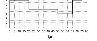
Schedule:
The graph shows the dependence of engine torque on its speed
What determines the amount of engine torque?
The basic unit of power in physics is the watt. In higher power machines, the watts are divided by a thousand to get kilowatts (kW).
horsepower as a unit of power And Horsepower is calculated differently in different countries.
Calculation example for Audi Q7 engine: Metric HP : hp : 78.5 kW / 0.7355 = 106.8 hp 157.1 kW / 0.7355 = 213.6 hp 175.9 kW / 0.7355 = 239.2 hp
Mechanical HP : 78.5 kW / 0.7457 = 105.3 HP 157.1 kW / 0.7457 = 210.6 hp 175.9 kW / 0.7457 = 235.9 hp
Note that Audi lists its engine's maximum power at 240 hp, which sounds best from a marketing perspective.
What kind of lighting do you prefer?
Built-in Chandelier
What does torque depend on?
The CM will be influenced by:
- Engine capacity.
- Cylinder pressure.
- Piston area.
- Crankshaft crank radius.
The basic mechanics of CM formation is that the larger the engine in volume, the more it will load the piston. That is, the KM value will be higher. The relationship with the radius of the crankshaft crank is similar, but this is secondary: in modern engines this radius cannot be changed much.
The pressure in the combustion chamber is an equally important factor. The force pressing on the piston directly depends on it.
To reduce torque losses when the car shakes during sharp throttle, you can use a compensator. This is a special (hand-assembled) damper, compensation of which will preserve torque and increase the service life of parts.
Why is torque important?
Torque, especially when designing systems with motors that provide the correct amount of torque, is incredibly important in a wide range of different applications.
Let's say you're building a robot. If you want to build a larger robot or a robot that can lift heavier objects, you will need more powerful motors that can produce more torque to make the robot move.
For aircraft, the torque produced by the engines directly determines the maximum lift the propellers can produce.
Figure 3 – Creation of lift by torque.
If you're building a car and want it to accelerate faster, you'll need more torque from the engines—in a car, the force moving it forward is equal to (roughly) the torque of the engine divided by the radius of the wheels.
Electric cars like the Tesla Model S are known for their fast acceleration because their electric motors generate enormous amounts of torque. This torque is directly transferred into a greater force applied by the wheels to the road surface. As basic physics teaches, applying more force to an object will cause it to accelerate faster.
What does torque affect?
The main goal of the CM is to gain power. Often powerful motors have a low KM indicator, so they are not able to accelerate the car quickly enough. This is especially true for gasoline engines.
IMPORTANT! When choosing a car, it is worth calculating the optimal ratio of torque to the number of revolutions at which the engine will most often operate. If you keep the torque at the appropriate level, this will allow you to optimally realize the engine's potential.
A high CM can also affect the car's handling, so when the speed increases sharply, it would be a good idea to use the TSC system. It allows you to more accurately direct the car during sudden acceleration.
The widely used 8-valve VAZ engine produces 120 torque (at 2500-2700 rpm). It doesn’t matter whether the car has a manual transmission or an automatic transmission. When using a gearbox, the driver’s experience is important; on an automatic transmission, a smooth start is ensured by the converter.
How to increase torque
Increase in working volume. To increase the efficiency, different methods are used: replacing the installed crankshaft with a shaft with increased eccentricity (a rare spare part that is difficult to find) or boring the cylinders for a larger piston diameter. Both methods have their pros and cons. The first requires a lot of time to select parts and reduces the durability of the engine. The second, increasing the diameter of the cylinders using boring, is more popular. Almost any car service can do this. There you can also adjust the carburetor to increase CM.
Changing the amount of boost. Turbocharged engines allow you to achieve a higher performance indicator due to design features - the ability to disable restrictions in the compressor control unit, which is responsible for boost. Manipulating the block will increase the pressure volume above the maximum specified by the manufacturer when assembling the car. The method can be called dangerous, since each engine has a limited supply of loads. In addition, additional improvements are often required: increasing the combustion chamber, bringing the cooling in line with the increased power. Sometimes you need to adjust the intake valve, sometimes you need to change the camshaft. It may be necessary to replace the cast iron crankshaft with a steel one and replace the pistons.
Torque meter
The main challenge in a torque meter using strain gauges is the accuracy of the data transfer. Previously used contact, induction and lighting devices did not guarantee the required efficiency. Nowadays data is transmitted via digital radio channels. The meter is a compact radio transmitter that is mounted on a shaft and transmits data to the receiver.
Now such devices are affordable and easy to use. They are mainly used in service stations.
Determination of torques on drive shafts
The torque on the electric motor shaft is determined by the formula
where NH is the rated power of the drive motor (NH = 2.2 kW);
nH – rated speed per minute of the electric motor (nH = 500 min-1).
The torque on the drive shafts is determined by the formula
where nI is the number of revolutions per minute of the first drive shaft (nI = 640 min-1);
— Efficiency of gears from the electric motor to the first shaft.
— Efficiency of the coupling (= 0.95);
— Efficiency of a pair of rolling bearings (= 0.99).
Substituting the found values, we get
The torque on the second drive shaft is determined by the formula
where nII is the number of revolutions per minute of the second shaft (nII = 640 min -1);
— Efficiency of the box from the first shaft to the second shaft, including gear transmission
— Efficiency of gear transmission (=0.97).
Substituting the found values of B
(4.4), we get
The torque on the third drive shaft is determined by the formula
where nIII is the number of revolutions per minute of the third drive shaft ( nIII = 250
min -1);
— Efficiency of the box from the first to the third shaft.
Substituting the found values into , we get
The torque on the fourth drive shaft is determined by the formula
where nIV is the number of revolutions per minute of the third drive shaft (nIV = 160
min -1)
— Efficiency of the box from the third to the fourth shaft
Substituting the found values, we get
Maximum torque
Maximum is the torque that represents the peak after which the torque does not increase, despite the number of revolutions. At low speeds, a large volume of residual gases accumulates in the cylinder, as a result of which the CM indicator is significantly lower than the peak. At medium speeds, more air enters the cylinders, the percentage of gases decreases, and torque continues to increase.
At high speeds, efficiency losses increase: from piston friction, inertial losses in the timing belt, oil heating, etc. the operation of the motor will depend. Therefore, the growth in engine performance quality stops or the quality itself begins to decline. Maximum torque has been reached and begins to decline.
In electric motors, the maximum torque is called “critical”.
Table of car brands indicating torque:
650-2000+
| VAZ car models | Torque (Nm, different engine brands) | |
| 2107 | 93 – 176 | |
| 2108 | 79-186 | |
| 2109 | 78-118 | |
| 2110 | 104-196 | |
| 2112 | 104-162 | |
| 2114 | 115-145 | |
| 2121 (Niva) | 116-129 | |
| 2115 | 103-132 | |
| 2106 | 92-116 | |
| 2101 | 85-92 | |
| 2105 | 85-186 | |
| ZMZ engines | ||
| 406 | 181,5-230 | |
| 409 | 230 | |
| Other popular car brands in Russia | ||
| Audi A6 | 500-750 | |
| BMW 5 | 290-760 | |
| Bugatti Veyron | 1250-1500 | |
| Daewoo Nexia | 123-150 | |
| KAMAZ | ||
| Kia Rio | 132-151 | |
| Lada Kalina | 127-148 | |
| Mazda 6 | 165-420 | |
| Mitsubishi Lancer | 143-343 | |
| UAZ Patriot | 217-235 | |
| Renault Logan | 112-152 | |
| Renault Duster | 156-240 | |
| Toyota Corolla | 128-173 | |
| Hyundai Accent | 106-235 | |
| Hyundai Solaris | 132-151 | |
| Chevrolet Captiv | 220-400 | |
| Chevrolet Cruze | 118-200 | |
Measure the engine torque yourself
We've looked at why staying within the engine's maximum torque is so important. So what should you do if you think your engine is not up to standard? Do not be afraid! We have a project that can show you how to measure the torque of a servo motor (in the next article).
Double check the torque of your servo motor before adding it to your project. This will help you take the frustration out of building and redoing things over and over again.
Original article:
- Scott Hatfield. What is Torque and Why Does it Matter?
Which engine to choose?
Today, manufacturers equip many models with different types of engines: gasoline or diesel. These models are identical only in price and other characteristics.
Due to different types of motor, the same model may differ in motor power and torque, and the difference can be significant.
Gas engine
A gasoline engine creates an air-fuel mixture that fills the cylinder. The temperature inside it rises to about 500 degrees. For such engines, the nominal compression ratio is about 9-10, less often 11 units. Therefore, when injection occurs, it is necessary to use spark plugs.
Diesel engine
In the cylinders of a diesel engine, the compression ratio of the mixture can reach 25 units, the temperature can reach 900 degrees. Therefore, the mixture is lit without the use of a candle.
Electric motor
An automobile three-phase asynchronous electric motor operates according to completely different laws, so its power and CM differ radically from traditional ones. The electric motor consists of a rotor and a stator, the multiplicity of which allows it to produce a peak power output (600 Nm) at any speed. At the same time, the power of the electric motor, for example, in Tesla, is 416 hp. With.
To answer the question - is a diesel, gasoline or electric motor better, we must first exclude the third option, since electric motors are not yet as common as the first two types.
IMPORTANT! When it comes to choosing between petrol and diesel engines, they primarily differ in power and torque. In practice, this means that with the same engine size, a diesel engine accelerates faster, while a gasoline engine allows for higher speeds.
In addition, due to the greater torque, a vehicle used as a truck has a greater load capacity due to the engine. Especially if the engine is a diesel generator.
What factors affect engine torque?
When it comes to maximum engine torque, there are three different but interrelated limiting factors.
Mechanical properties of materials
Firstly, these are the mechanical properties of materials. A good example of this design approach is the various servo motors.
Cheaper, lower torque servos use plastic gears, usually made of nylon. Plastic gears are inexpensive to produce, which makes servos with nylon gears cheaper to produce and therefore cheaper to buy. Nylon gears are also lighter than metal gears, which is an important factor for robotics and aircraft. However, if too much torque is applied to these nylon gears, they will break.
Higher torque servos contain metal gears so they can deliver higher torque without breaking.
The materials used in the engine's construction play a huge role in determining how much torque the engine will be able to produce.
Figure 4 - Motors are made from a variety of materials, but generally those made from metal have higher torque than those made from nylon or other plastic.
Maximum motor voltage
The second factor that affects the maximum torque of an engine is the maximum voltage that the engine is designed for. If you look at the specs page of any servo, you will find different torque values for different voltages. Higher voltages give the motor more power to produce higher torque. However, the motor and its control circuitry may only accept limited voltage due to the possibility of overheating and combustion. The maximum voltage a motor can accept without failure affects the amount of its maximum torque.
Figure 5 – The maximum motor voltage is indicated in the technical specifications provided by the manufacturers. Relationship between operating voltage and torque.
Engine heat dissipation
This brings us to the final factor that limits maximum engine torque. As engines run, they generate unnecessary heat. The harder an engine works, the more heat it generates.
For most motors used in hobby projects, from DC motors to servos and stepper motors, the heat generated is simply radiated into the air. They do not have active cooling, such as in an electric car. Therefore, the motor is limited by how much torque (as well as speed) it can generate without risking thermal failure.