In electromechanics, there are many drives that operate with constant loads without changing the rotation speed. They are used in industrial and household equipment such as fans, compressors and others. If the nominal characteristics are unknown, then the electric motor power formula is used for calculations. Parameter calculations are especially relevant for new and little-known drives. Calculation is performed using special coefficients, as well as based on accumulated experience in working with similar mechanisms. The data is necessary for the correct operation of electrical installations.
What is an electric motor?
An electric motor is a device that converts electrical energy into mechanical energy. The operation of most units depends on the interaction of the magnetic field with the rotor winding, which is expressed in its rotation. They operate from DC or AC power sources. The power supply can be a battery, an inverter or a power outlet. In some cases, the engine works in reverse, that is, it converts mechanical energy into electrical energy. Such installations are widely used in power plants powered by air or water flow.
Electric motors are classified by type of power source, internal design, application and power. Also, AC drives may have special brushes. They operate on single-phase, two-phase or three-phase voltage and are air or liquid cooled. AC motor power formula
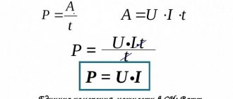
P = U x I,
where P is power, U is voltage, I is current.
General purpose drives with their own sizes and characteristics are used in industry. The largest engines with a power of more than 100 Megawatts are used in the power plants of ships, compressor and pumping stations. Smaller sizes are used in household appliances, such as a vacuum cleaner or fan.
Power by current
Calculation of the power of an asynchronous motor can be done using current data. To do this, follow these steps:
- Apply power to the engine.
- Using an ammeter, measure the current in each turn.
- Calculate the average current value based on the measurements performed in the second paragraph.
- Multiply the average current by the voltage. You will get power.
Power can always be calculated as the product of current and voltage. In this case, it is important to know which values of U and I should be taken. In this case, U is the supply voltage, it is a constant value, and I can vary depending on which winding (stator or rotor) the current is measured, so it is necessary to select its average value.
Electric motor design
Drive includes:
- Rotor.
- Stator.
- Bearings.
- Air gap.
- Winding.
- Switch.
The rotor is the only moving part of the drive that rotates around its axis. The current passing through the conductors forms an inductive disturbance in the winding. The generated magnetic field interacts with the permanent magnets of the stator, which causes the shaft to move. They are calculated using the formula for electric motor power by current, for which the efficiency and power factor are taken, including all the dynamic characteristics of the shaft.
Bearings are located on the rotor shaft and contribute to its rotation around its axis. The outer part is attached to the engine housing. The shaft passes through them and comes out. Since the load extends beyond the working area of the bearings, it is called overhanging.
The stator is a stationary element of the electromagnetic circuit of the engine. May include winding or permanent magnets. The stator core is made of thin metal plates called the armature package. It is designed to reduce energy loss, which often occurs with solid rods.
Air gap is the distance between the rotor and stator. A short gap is effective, as it affects the low efficiency of the electric motor. The magnetizing current increases with increasing gap size. Therefore, they always try to make it minimal, but to reasonable limits. Too small a distance leads to friction and weakening of the fixing elements.
The winding consists of copper wire assembled into one coil. Typically laid around a soft magnetized core consisting of several layers of metal. The induction field is disturbed when current passes through the wires of the winding. At this point, the installation enters configuration mode with explicit and implicit poles. In the first case, the magnetic field of the installation is created by a winding around the pole piece. In the second case, the slots of the rotor pole piece are dispersed in the distributed field. A shaded pole motor has a winding that inhibits magnetic disturbance.
The switch is used to switch the input voltage. It consists of slip rings located on the shaft and isolated from each other. The armature current is supplied to the contact brushes of the rotary commutator, which causes a change in polarity and causes the rotor to rotate from pole to pole. If there is no voltage, the motor stops turning. Modern installations are equipped with additional electronic means that control the rotation process.
Calculation of power by engine volume
The attentive reader probably noticed that the first formula can be directly substituted into the second to simplify the calculations. The power in this case can be expressed as follows:
M = (KM x OD)/9549 = (O x D x OD)/(9549 x 0.0126) = (O x D x OD)/120.3.
The decoding of this formula will be standard:
- O - engine volume.
- D is the pressure in the combustion chamber.
- OD - revolutions.
- 120.3 is the new correction factor.
Please note that the pressure in the combustion chamber (variable D) in the case of a standard gasoline engine is usually in the range from 0.8 to 0.85 MPa . In the case of a reinforced forced engine, this figure will be 0.9 MPa , in the case of a diesel engine - from 1 to 2 MPa .
Operating principle
According to Archimedes' law, the current in a conductor creates a magnetic field in which the force F1 acts. If a metal frame is made from this conductor and placed in a field at an angle of 90°, then the edges will experience forces directed in the opposite direction relative to each other. They create a torque about the axis, which begins to rotate it. The armature coils provide constant torsion. The field is created by electric or permanent magnets. The first option is made in the form of a coil winding on a steel core. Thus, the frame current generates an induction field in the electromagnet winding, which generates an electromotive force.
Let us consider in more detail the operation of asynchronous motors using the example of installations with a wound rotor. Such machines operate on alternating current with an armature rotation frequency that is not equal to the pulsation of the magnetic field. That's why they are also called induction. The rotor is driven by the interaction of electric current in coils with a magnetic field.
When there is no voltage in the auxiliary winding, the device is at rest. As soon as an electric current appears at the stator contacts, a constant magnetic field with pulsation +F and -F is formed. It can be represented as the following formula:
npr = nrev = f1 × 60 ÷ p = n1
Where:
npr is the number of revolutions that the magnetic field makes in the forward direction, rpm;
nrev — number of field revolutions in the opposite direction, rpm;
f1—electric current pulsation frequency, Hz;
p—number of poles;
n1 is the total number of revolutions per minute.
Experiencing pulsations of the magnetic field, the rotor receives initial movement. Due to the heterogeneity of the impact of the flow, it will develop a torque. According to the law of induction, an electromotive force is generated in a short-circuited winding, which generates a current. Its frequency is proportional to the rotor slip. Due to the interaction of electric current with a magnetic field, shaft torque is created.
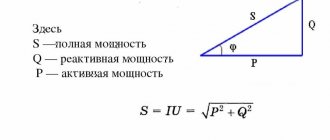
To calculate performance, there are three formulas for the power of an asynchronous electric motor. By phase shift they use
S = P ÷ cos (alpha), where:
S is the total power, measured in Volt-Amps.
P is active power, indicated in Watts.
alpha - phase shift.
By total power we mean the real indicator, and by active - the calculated one.
Calculations of the main parameters of an asynchronous electric motor
Active power is spent to perform useful work and create heat. Denoted by the letter " P ", measured in W and calculated:
P = I * U * cos φ.
Reactive power is created by fluctuations in the energy of the electric field. It determines the ability of jet engine parts to store and emit electromagnetic energy. We are talking about the current that charges a capacitor or creates a magnetic field around the turns of a coil winding. Denoted by the letter " Q ", measured in Var and calculated:
Q=I*U*sinφ.
The total power " S " is represented by a mathematical combination according to the formula of the Pythagorean theorem: S*S = Q*Q + P*P . It is measured in V*A and is calculated:
S = P / cos φ = √(P2 + Q2)=I*U.
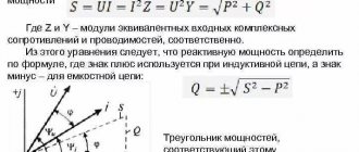
The reactive power of a three-phase asynchronous motor can be represented as the sum of two components: inductive and capacitive.
The best representation of this quantity can be obtained in the form of a vector diagram, the inductive component is a positive coordinate on the Y axis, the capacitive component is negative. Obviously, these two values cancel each other out somewhat, making up a vector coordinate that will be either positive or negative. The smaller the angle between them, the closer the total power becomes to the active one.
The power factor cosφ for a three-phase asynchronous motor is 0.8–0.9. If it needs to be increased, then quite often capacitors are added to the motor circuits. The function of these capacitors is to provide a magnetizing current that reduces the amplitude of the reactive component. The higher the cosφ , the less energy the electric machine consumes.
Types of electric motors
Based on the power source, drives are divided into those powered by:
- Direct current.
- Alternating current.
According to the principle of operation, they, in turn, are divided into:
- Collector.
- Valve.
- Asynchronous.
- Synchronous.
Valve motors are not classified as a separate class, since their design is a variation of a commutator drive. Their design includes an electronic converter and a rotor position sensor. They are usually integrated together with a control board. Due to them, coordinated commutation of the armature occurs.
Synchronous and asynchronous motors operate exclusively on alternating current. The speed is controlled using sophisticated electronics. Asynchronous are divided into:
- Three-phase.
- Two-phase.
- Single-phase.
Theoretical formula for the power of a three-phase electric motor when connected in a star or delta
P = 3 * Uph * Iph * cos(alpha).
However, for linear values of voltage and current it looks like
P = 1.73 × Uph × Iph × cos(alpha).
This will be a real indicator of how much power the engine takes from the network.
Synchronous are divided into:
- Stepper.
- Hybrid.
- Inductor.
- Hysteretic.
- Reactive.
Stepper motors have permanent magnets in their design, so they are not classified as a separate category. The operation of the mechanisms is controlled using frequency converters. There are also universal motors that operate on direct and alternating current.
General characteristics of engines
All motors have common parameters that are used in the formula for determining the power of an electric motor. Based on them, the properties of the machine can be calculated. In different literature they may be called differently, but they mean the same thing. The list of such parameters includes:
- Torque.
- Engine power.
- Efficiency.
- Nominal speed.
- Rotor moment of inertia.
- Design voltage.
- Electrical time constant.
The above parameters are necessary, first of all, to determine the efficiency of electrical installations operating due to the mechanical force of motors. Calculated values give only an approximate idea of the actual characteristics of the product. However, these indicators often use electric motor power in the formula. It is this that determines the performance of the machines.
Calculation of electric motor power for equipment
To determine how much power an electric motor needs to service a particular mechanism, you need to know its (the mechanism’s) power consumption. It is usually indicated for each category of installations and devices, is written in the passport documentation and is known to the manufacturer. If there is no factual information on the indicator, it can be obtained:
- based on the results of theoretical calculations;
- empirically, using the results of numerous experiments;
- by the method of taking load diagrams, if an experimental base of operation has not yet been accumulated (the equipment has been poorly studied), recording devices are needed here;
- through the use of energy consumption standards (statistical data), which take into account the specific consumption of electrical energy when creating a specific product.
When consumption is known, all that remains is to substitute it into the following formula.
, Where:
- Рм – theoretically/empirically determined or rated power of the equipment;
- – efficiency factor of the intermediate gear.
The calculated indicator is used to select products from the PTC “Privod” product catalog. In this case, you should focus on the rated power indicators of the electric motor with a small margin.
There is no need to check the electric motor for load or overheating. At the stage of quality control of finished products, our production and technical center carries out all tests and calculations with the maximum use of materials that are included in the models when calculating the nominal power of the electric motor. But monitoring the adequacy of the starting torque for some types of connected mechanisms can be useful. This especially applies to devices with increased friction resistance at the start (conveyors, working units of metal cutting machines).
Energy efficiency of the electric motor
Like all electrical appliances that consume electrical energy (a paid resource), the electric motor has its own energy efficiency class. The production costs of operating the device depend on this indicator. It, in turn, depends on the efficiency of the engine and is indicated in the technical documentation. As practice shows, even in the average category of electric motors (55 kW), preference for versions with a higher energy efficiency class can significantly reduce energy costs (savings up to 10 thousand kW per year).
You can select an installation of the optimal energy efficiency class according to the product catalog of PTC “Privod” - the description of the models contains all the necessary information. Here you can also order an electric motor power regulator, which also helps reduce energy consumption and ensures smooth operation of the device without jerking (increases its service life).
Torque
This term has several synonyms: torque, motor torque, torque, torque. All of them are used to denote one indicator, although from the point of view of physics these concepts are not always identical.
In order to unify terminology, standards have been developed that bring everything to a single system. Therefore, in technical documentation the phrase “torque” is always used. It is a vector physical quantity that is equal to the product of the vector values of force and radius. The radius vector is drawn from the axis of rotation to the point of applied force. From a physics perspective, the difference between torque and torque lies in the point at which the force is applied. In the first case it is an internal effort, in the second it is an external one. The value is measured in newton meters. However, in the electric motor power formula, torque is used as the main value.
It is calculated as
M = F × r, where:
M — torque, Nm;
F is the applied force, H;
r—radius, m.
To calculate the rated torque of the drive, use the formula
Mnom = 30Рnom ÷ pi × nnom, where:
Rnom - rated power of the electric motor, W;
nnom - nominal speed, min-1.
Accordingly, the formula for the rated power of the electric motor should look like this:
Pnom = Mnom * pi*nnom / 30.
Usually all characteristics are indicated in the specification. But it happens that you have to work with completely new installations, information about which is very difficult to find. To calculate the technical parameters of such devices, data from their analogs is taken. Also, only the nominal characteristics that are given in the specification are always known. Real data must be calculated independently.
Power via torque
One way to calculate power is to determine the dependence of motor torque on the number of revolutions.
Any moment in physics is the product of a force and the shoulder of its application. Torque is the product of the force that the engine can develop to overcome the resistance of the load and the shoulder of its application. It is this parameter that determines how quickly the motor reaches its maximum power.
Torque can be defined as the ratio of the product of the working volume and the average effective pressure in the combustion chamber to 0.12566 (constant):
- M = (Vworking * Peffective)/0.12566, where Vworking is the working volume of the engine [l], Peffective is the effective pressure in the combustion chamber [bar].
Engine speed characterizes the speed of rotation of the crankshaft.
Using the values of torque and engine speed, you can use the following formula to calculate engine power:
- P = (M * n)/9549, where M – torque [Nm], n – shaft rotation speed [rpm], 9549 – proportionality coefficient.
The calculated power is measured in kilowatts. To convert the calculated value into horsepower, you need to multiply the result by a proportionality coefficient of 1.36.
This method of calculation consists of using only two elementary formulas, therefore it is considered one of the simplest. True, you can do it even simpler and use an online calculator, into which you need to enter certain data about the car and its engine unit.
It is worth noting that this formula for calculating engine power allows you to calculate only the power that is obtained at the output of the engine, and not that which actually reaches the wheels of the car. What is the difference? While the power (if you imagine it as a flow) reaches the wheels, it experiences losses in the transfer case, for example. Secondary consumers such as an air conditioner or generator also play a significant role. It is impossible not to mention the losses due to overcoming resistance to lifting, rolling, and aerodynamic resistance.
This disadvantage is partially compensated by the use of other calculation formulas.
Engine power
In a general sense, this parameter is a scalar physical quantity, which is expressed in the rate of consumption or conversion of energy of the system. It shows how much work the mechanism will perform in a certain unit of time. In electrical engineering, the characteristic displays the useful mechanical power on the central shaft. To designate the indicator, use the letter P or W. The main unit of measurement is Watt. The general formula for calculating the power of an electric motor can be presented as:
P = dA ÷ dt, where:
A—mechanical (useful) work (energy), J;
t — time spent, sec.
Mechanical work is also a scalar physical quantity, expressed by the action of a force on an object, and depending on the direction and movement of this object. It is the product of the force vector and the path:
dA = F × ds, where:
s — distance traveled, m.
It expresses the distance that a point of applied force will travel. For rotational movements it is expressed as:
ds = r × d(teta), where:
theta — rotation angle, rad.
In this way, you can calculate the angular frequency of the rotor:
omega = d(teta) ÷ dt.
From this follows the formula for the power of the electric motor on the shaft: P = M × omega.
Introduction
There are at least four common ways to calculate the power of an internal combustion engine. These methods use the following parameters of the propulsion unit:
- Revolutions.
- Volume.
- Torque.
- Effective pressure inside the combustion chamber.
For calculations, you need to know the weight of the car, as well as the acceleration time to 100 km/h.
Each of the following formulas for calculating engine power has some error and cannot give a 100% accurate result. This should always be taken into account when analyzing the data obtained.
If you calculate the power using all the formulas that will be described in the article, you can find out the average value of the actual engine power, and the discrepancy with the actual result will be no more than 10%.
If we do not take into account various scientific subtleties associated with the definition of technical concepts, we can say that power is the energy generated by the motor unit and converted into torque on the shaft. In this case, power is not a constant quantity, and its maximum value is achieved at a certain shaft rotation speed (indicated in the passport data).
In modern internal combustion engines, maximum power is achieved at 5.5-6.6 thousand revolutions per minute. It is observed at the highest average effective pressure in the cylinders. The magnitude of this pressure depends on the following parameters:
- quality of the fuel mixture;
- combustion completeness;
- fuel losses.
Power, as a physical quantity, is measured in Watts, and in the automotive industry it is measured in horsepower. The calculations described in the methods below will give results in kilowatts, then they will need to be converted to horsepower using a special converter calculator.
Nominal speed
Another key indicator of the electromechanical characteristics of the engine is the shaft speed. It is expressed in revolutions per minute. It is often used in the pump motor power formula to find out its performance. But it must be remembered that the indicator is always different for idling and operation under load. The indicator represents a physical quantity equal to the number of full revolutions over a certain period of time.
Calculation formula for speed:
n = 30 × omega ÷ pi, where:
n — engine speed, rpm.
In order to find the power of an electric motor using the shaft speed formula, it is necessary to reduce it to the calculation of angular velocity. Therefore P = M × omega will look like this:
P = M × (2pi × n ÷ 60) = M × (n ÷ 9.55), where
t = 60 seconds.
Electric motor power by installation and overall dimensions
Did you like the video? Subscribe to our channel!
For the first method, you need to know the installation dimensions of the electric motor and the synchronous speed. The latter is measured using a multimeter set to milliammeter mode. To do this, set the selection wheel pointer to 100µA. We connect the black probe to the common “COM” socket, and the red probe to the socket for measuring voltage, resistance and current up to 10 A.
After this, de-energize the electric motor and remove the cover from the terminal box.
We connect the multimeter probes to the beginning and end of any of the windings (for example, V1 and V2). After this, we slowly turn the motor shaft by hand so that it makes one revolution, and count the number of deviations of the needle from rest that it will make during this time. The number of pointer deflections per shaft revolution is equal to the number of poles and corresponds to the following synchronous rotation speed:
• 2 poles – 3000 rpm;
• 4 poles – 1500 rpm;
• 6 poles – 1000 rpm;
• 8 poles – 750 rpm.
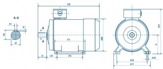
Now you need to find out the installation dimensions of the engine. For measurements we use calipers, mechanical or electronic, as well as a measuring tape. We record the measurement results in millimeters: the diameter and length of the shaft extension, the height of the axis of rotation, the distance between the centers of the holes in the “legs”, and if the engine is flanged, then the diameter of the flange and the diameter of the mounting holes.
We compare the obtained data with the parameters from tables 1-3.
Design voltage
It is also called nominal. It is a base voltage represented by a standard set of voltages, which are determined by the degree of insulation of electrical equipment and the network. In reality, it may differ at different points of the equipment, but should not exceed the maximum permissible operating conditions designed for the long-term operation of the mechanisms.
For conventional installations, rated voltage refers to the calculated values for which they are provided by the developer in normal operation. The list of standard network voltage is provided in GOST. These parameters are always described in the technical characteristics of the mechanisms. To calculate performance, use the formula for electric motor power by current:
P = U × I.
Electrical time constant
Represents the time required for the current level to reach 63% after voltage is applied to the drive windings. The parameter is determined by transient processes of electromechanical characteristics, since they are fleeting due to high active resistance. General formula for calculating the time constant:
te = L ÷ R.
However, the electromechanical time constant tm is always greater than the electromagnetic time constant te. The first parameter is obtained from the equation of the dynamic characteristics of the engine while maintaining the condition when the rotor accelerates from zero speed to maximum idle speed. In this case, the equation takes the form
M = Mst + J × (d(omega) ÷ dt), where
Mst = 0.
From here we get the formula:
M = J × (d(omega) ÷ dt).
In fact, the electromechanical time constant is calculated from the starting torque - MP. A mechanism operating under ideal conditions with linear characteristics will have the formula:
M = Mп × (1 - omega ÷ omega0), where
omega0 — idle speed.
Such calculations are used in the formula for the power of a pump electric motor, when the piston stroke directly depends on the speed of the shaft.
Basic formulas for calculating engine power
To calculate the actual characteristics of mechanisms, many parameters must always be taken into account. First of all, you need to know what kind of current is supplied to the windings of the electric motor: direct or alternating. The principle of their operation is different, therefore the calculation method is different. If a simplified form of calculating drive power looks like:
Pel = U × I, where
I—current strength, A;
U—voltage, V;
Rel - supplied electrical power. Tue
In the AC motor power formula, phase shift (alpha) must also be taken into account. Accordingly, the calculations for an asynchronous drive look like:
Pel = U × I × cos(alpha).
In addition to active (supplied) power, there is also:
- S - reactive, VA. S = P ÷ cos(alpha).
- Q - full, VA. Q = I × U × sin(alpha).
The calculations also need to take into account heat and induction losses, as well as friction. Therefore, a simplified model formula for a DC motor looks like:
Rel = Pmech + Rtep + Rind + Rtr, where
Рmekh - useful generated power, W;
Rtep—losses for heat generation, VT;
Rind is the cost of charging in the induction coil, W;
RT - losses due to friction, W.
Power through the mass of the car and acceleration time to “hundreds”
Calculation using the weight of the car and its acceleration speed to 100 km/h is one of the simplest methods for calculating the real engine power, because the weight of the car and the stated acceleration time to “hundreds” are the vehicle’s passport parameters.
This method is relevant for engines running on any type of fuel - gasoline, diesel fuel, gas - because it only takes into account the dynamics of acceleration.
When calculating, it is worth taking into account the weight of the vehicle along with the driver. Also, in order to bring the calculation result as close as possible to the actual one, it is worth taking into account the losses spent on braking, slipping, as well as the reaction speed of the gearbox. The type of drive also plays a role. For example, front-wheel drive cars lose about 0.5 seconds at the start, rear-wheel drive cars lose from 0.3 to 0.4 seconds.
All that remains is to find a calculator on the Internet to calculate the power of a car through acceleration speed, enter the necessary data and get an answer. There is no point in presenting the mathematical calculations that the calculator makes because of their complexity.
The result of the calculations will be one of the most accurate, close to the real one.
This method of calculating the real power of a car is considered by many to be the most convenient, because car owners will have to make a minimum of effort - to measure the acceleration speed of up to 100 km/h for the purity of the experiment and enter additional data into an automatic calculator.