AC power
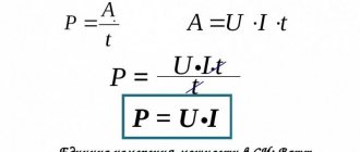
Within an alternating current circuit, there are three types of power: active type or P, reactive type or Q, and full type or S. In the first case, the standard unit of measurement is the Watt (W or W), and the formula for calculating active power parameters is:
P = U × I × cos φ.
The calculations of positive or negative active power directly depend on the characteristics of the phase shift angle coefficient or the latter indicator.
For reactive type power measurements, a special volt-ampere with the designation “Var” or Var is used.
This value characterizes the loads that are formed inside electrical structures under the influence of oscillations of electromagnetic fields in alternating sinusoidal current circuits.
The calculation is carried out on the basis of root-mean-square voltage and current parameters multiplied by the angular sinusoid of the phase shift, according to the values:
Q = U × I × sin φ.
In conditions of values at the level of 0/+90°, the sine value will be positive, and for values within the range of 0/-90° - only negative. Measurements of total electrical power are carried out exclusively in volt-amperes (VA or V A).
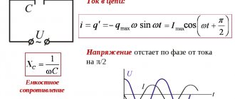
Dependence of power on time for alternating and direct current
The value corresponding to the product of the standard voltage in the clamping area with the indicators of periodic electric current inside the circuit should be calculated in accordance with the formulas:
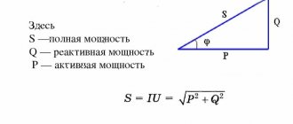
S = U × I or S = √Р2 + Q2, where
- the P value is represented by active power;
- Q2 value is an indicator of reactive power.
Of no small importance is the complex power corresponding to the impedance. In any case, it must be taken into account that positive power corresponds to P > 0, and negative power corresponds to P < 0.
Large domestic producers of electrical energy generate alternating current with a so-called industrial frequency of 50 Hz and voltage levels in the range of 10-20 kV, and the electrical voltage is increased at special transformer substations.
Calculations and equations
Formula for complex power (unit: VA) in phasor form:
S = V i ∗ = | S | ∠ φ { Displaystyle S = VI ^ {*} = | S | angle varphi} ,
where V
denotes voltage in vector form, with amplitude as rms, and
i
denotes current in vector form, with rms amplitude.
Also by convention, the complex conjugate of i
is used, which is denoted by i ∗ { displaystyle I ^ {*)} (or i ¯ { displaystyle { overline {I))} rather than
by
itself. This is done because otherwise using the product VI to define S will result in a quantity that depends on the original angle chosen for V or I, but defining S as VI* results in a quantity that is independent of the original angle and allows S to be related with P and Q.[5]
Other forms of complex power (units in volt-amperes, VA) are derived from Z
, Loading resistance (units in ohms, ohms).
S = |
I | 2 Z = | V | 2 Z ∗ { Displaystyle S = | I | ^{2}Z = {frac {| V | ^{2}}{Z^{*}}}}. Therefore, with reference to the power triangle, real power (units of watts, W) is defined as:
n = | S | because φ = | I | 2 p = | V | 2 | Z | 2 × P { displaystyle P = | S | cos{varphi} = | I | ^{2}R = {frac {| V | ^{2}}{| Z | ^ {2}}} times {R }} .
For a purely resistive load, the actual power can be simplified to:
n = | V | 2 P { Displaystyle P = { frac {| V | ^{2}}{R}}}.
R
denotes the resistance (units in ohms, ohms) of the load.
Reactive power (units in volt-amps, reactive power) is calculated as:
Q = | S | sin φ = | I | 2 x = | V | 2 | Z | 2 × X { Displaystyle Q = | S | sin {varphi} = | I | ^{2}X = {frac {| V | ^{2}}{| Z | ^ {2}}} times {X }} .
For a purely reactive load, reactive power can be simplified to:
Q = | V | 2 X { displaystyle Q = { frac {| V | ^{2}}{X}}},
where to X
denotes the reactance (units in ohms, ohms) of the load.
Combining, complex power (units in volt-amperes, VA) is calculated back as
S = P + j Q { Displaystyle S = P + jQ } ,
and apparent power (units in volt-amperes, VA) as
| S | = p 2 + Q 2 { displaystyle | S | = { sqrt {P^{2} + Q^{2}}}} .
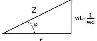
They are schematically simplified by the power triangle.
AC Power Formula
The power indicators of an alternating type electric current are the product of the current data and the voltage, and the level will be zero in conditions of passing through zero, but necessarily maximum at the peak amplitude.
Despite the complexity of measuring power, it is important to remember that such data are not representative, so from a practical point of view, the active average power in a certain period is of interest.
Multi-frequency systems
Since the RMS value can be calculated for any waveform, the apparent power can be calculated from it. For active power, it may initially seem like you need to calculate many product parameters and average them all. However, a closer look at one of these product terms yields a very interesting result.
And because ( ω 1 t + k 1 ) because ( ω 2 t + k 2 ) = A 2 because [ ( ω 1 t + k 1 ) + ( ω 2 t + k 2 ) ] + A 2 because [ ( ω 1 t + k 1 ) − ( ω 2 t + k 2 ) ] = A 2 because [ ( ω 1 + ω 2 ) t + k 1 + k 2 ] + A 2 because [ ( ω 1 − ω 2 ) t + k 1 − k 2 ] { displaystyle { begin {align} & A cos ( omega _ {1} t + k_ {1}) cos ( omega _ {2} t + k_ {2}) = {} & { frac {A} {2}} cos left [ left ( omega _ {1} t + k_ {1} right) + left ( omega _ {2} t + k_ {2} right ) right] + { frac {A} {2}} cos left [ left ( omega _ {1} t + k_ {1} right) — left ( omega _ {2} t + k_ {2} right) right] = {} & { frac {A} {2}} cos left [ left ( omega _ {1} + omega _ {2} right) t + k_ {1} + k_ {2} right] + { frac {A} { 2}} cos left [ left ( omega _ {1} - omega _ {2} right) t + k_ {1} -k_ {2} right] end {aligned}}}
However, the time-average function of the form cos ( ωt
+
k
) is equal to zero provided that
ω
is not equal to zero. Therefore, the only product terms that have a non-zero mean are those in which the frequency of the voltage and current are the same. In other words, you can calculate the active (average) power by simply looking at each frequency separately and adding up the responses. Also, if the power supply voltage is assumed to be single frequency (which it usually is), this shows that harmonic currents are bad. They increase the rms current (since non-zero terms will be added) and therefore the apparent power, but they will not affect the active power transferred. Consequently, harmonic currents reduce the power factor. Harmonic currents can be reduced by using a filter installed at the input of the device. Typically this will either be a simple capacitor (depending on the parasitic resistance and inductance in the power supply) or a capacitor-inductor circuit. Active Power Factor Correction The input circuit typically further reduces harmonic currents and maintains a power factor close to unity.
In a single-phase circuit
For a single-phase circuit, the formula for determining the total power is used: S = U × I , where
- S —indicators of total power characteristics (Ba);
- I is the level of effective electric current taking into account the generator winding (A);
- U - parameters of the calculated effective voltage value in the generator (V).
The full power characteristics taken into account in standard independent calculations affect the dimensions of the generator with variable electric current, which is determined by the cross-section and number of turns of the winding wires, as well as the thickness of the insulating material. For active and reactive resistance, the power consumed in active resistance and in the reactive part is important.
Single-phase AC electrical circuits
Reactive power indicators are caused by energy fluctuations under conditions of the formation and loss of electric or magnetic fields. The electrical energy stored within the field of such resistance is progressively returned back to the generator, which is connected to a standard electrical circuit.
The presence of reactive currents between the reactive receiver and the generator, which have inductive and capacitive reactance, contributes to the useless load of the line and generator, which is accompanied by additional energy losses.
Strength Factor
Main article: Force factor
The ratio of active power to apparent power in a circuit is called the force factor. For two systems transmitting the same amount of active power, the system with the lower power factor will have higher circulating currents due to the energy that returns to the source from the energy storage in the load. These higher currents cause higher losses and reduce overall transmission efficiency. A circuit with a lower power factor will have higher apparent power and higher losses for the same amount of active power. Power factor is 1.0 when voltage and current are in phase. It is zero when the current leads or lags the voltage by 90 degrees. When voltage and current are 180 degrees out of phase, the power factor is negative and the load supplies power to the source (an example would be a house with solar panels on the roof that feed power to the grid when the sun is shining). Power factors are usually specified as "leading" or "lag" to show the sign of the phase shift of the current relative to the voltage. The voltage is designated as the base to which the angle of the current is compared, which means that the current is treated as a "leading" or "lag" voltage. If the waveform is purely sinusoidal, the power factor is the cosine of the phase angle (φ { displaystyle varphi} ) between the sinusoidal current and voltage signals. In equipment data sheets and nameplates, power factor is often abbreviated as "cos ϕ { displaystyle cos phi} " for this reason.
Example: active power is 700 W and the phase angle between voltage and current is 45.6°. The power factor is cos(45.6°) = 0.700. Then the apparent power is: 700 W / cos (45.6 °) = 1000 VA. The concept of power dissipation in an AC circuit is explained and illustrated with an example.
For example, a power factor of 0.68 means that only 68 percent of the total current supplied (by magnitude) is actually doing work; the remaining 32% do not work. Typically, utilities do not charge customers for reactive power losses because they do not perform any actual work for the customer. However, if there is inefficiency at a customer's load source that causes the power factor to fall below a certain level, utilities may charge customers a fee to cover the increase in plant fuel use and the decrease in line and plant capacity.
In a three-phase circuit
The power indicators of alternating current with a uniform three-phase load are determined by the presence of an equivalent current flowing through the conductors of the phase. In this case, the current indicators under the conditions of using the neutral conductor are “O”. Formula for calculating alternating current power under three-phase network conditions: P = 3 × U φ × I × cos(φ).
Symmetrical (uniform) phase load in a three-wire three-phase current circuit
The flow of currents of different magnitudes inside phase conductors represents an asymmetrical or uneven load. In this case, it is the asymmetrical load that is accompanied by the flow of current through the zero or neutral wires, therefore the level of power indicators is determined in accordance with the standard and well-known formula:
Total = Ua × Ia × cos(φ1) + Ub × Ib × cos(φ2) + Uс × Iс × cos(φ3).
Average power in active load
The power parameters of the electrical network or any installation are the most important data of almost any electrical device. The transmission of passing or consumed power characteristics of the active type is carried out over a certain period of time.
Table values of average power characteristics of main household appliances
| Device | Indicators |
| Charger | 2.0 W/hour |
| Fluorescent lamps "DRL" | 50 W/hour or more |
| Electric kettle | 1.5 kW/hour |
| Acustic systems | 30 W/hour |
| Washing machine | 2.5 kW/hour |
| High pressure washing | 3.5 kW/hour |
| Semi-automatic inverters | 3.5 kW/hour |
| Kitchen blender | 1.0-1.2 kW/hour |
| Microwave oven | 1.8 kW/hour |
| Kitchen toasters | 1.2 kW/hour |
| TV | 0.2 kW |
| Fridge | 0.4 kW |
| Vacuum cleaner | 1.0 kW |
| Desktop computer | 0.55 kW |
| Electric stove | 2.5 kW/hour |
| Hair dryer | 1.0 kW/hour |
| Iron | 1.0 kW/hour |
| Electric oven | 1.2 kW/hour |
| Electric heater | 1.4 kW/hour |
Power in the presence of a phase shift between current and voltage
Under conditions of alternating electric current, coincidences in current direction and voltage are noted only in the absence of coil induction and capacitors. In this case, the vector directions of current and voltage are identical. The presence of coils and a capacitor in the circuit is accompanied by the coincidence of current phases and voltage indicators, but vector rotation occurs at the same speed and at constant angle parameters.
The phase shift or shift coincides with the angle that is observed between the vector radii of the current indicators and voltage parameters, and a lag in these criteria provokes a mismatch.
AC current and voltage phase shift
In this case, the power characteristics are negative due to the product of positive and negative quantities. In such conditions, an external type electrical circuit becomes the standard source of electricity. A small amount of energy entering the circuit at positive power values is returned only in the presence of negative values.
The duration of parts of the period directly depends on the level of phase shift, while the displacement indicators are determined by the duration of negative powers, or the so-called average power characteristics of the electric current.
Real number formulas
An ideal resistor does not store energy; therefore the current and voltage are in phase. Therefore, there is no reactive power and P = S { Displaystyle P = S} (using the passive sign convention). Therefore, for an ideal resistor
P = S = V R MS I R MS = I R MS 2 R = V R MS 2 R { displaystyle P = S = V_{ mathrm {RMS} } I_{ mathrm {RMS} } = I_{ mathrm { RMS}} ^ {2} R = { frac {V _ { mathrm {RMS}} ^ {2}} {R}} , !} .
For an ideal capacitor or inductor there is no useful power transfer; so all power is reactive. Therefore, for an ideal capacitor or inductor:
n = 0 Q = | S | = V r MS i r MS = i r MS 2 | X | = V p MS 2 | X | { displaystyle { begin {align} P & = 0 Q & = | S | = V_{ mathrm {RMS}} I_{ mathrm {RMS}} = I_{ mathrm {RMS}} ^{2} | X | = { frac {V_{ mathrm {RMS}} ^{2}} {| X |}} end {align}}} .
where X { displaystyle X}
This is the reactance of a capacitor or inductor.
If X { displaystyle X} is defined as positive for the inductor and negative for the capacitor, then the modulus signs can be removed from S and X to obtain
Q = I R MS 2 X = V R MS 2 X { displaystyle Q = I _ { mathrm {RMS} } ^{2} X = { frac {V_{ mathrm {RMS} } ^{2} } {X} }} .
Instantaneous power is defined as:
P inst ( t ) = V ( t ) ⋅ I ( t ) { Displaystyle P_{ text {inst)) (t) = V ( t ) CDOT I ( t )} ,
where V ( t ) { Displaystyle V ( t )} and I ( t ) { Displaystyle I ( t )} are time-varying voltage and current waveforms.
This definition is useful because it applies to all signals, whether they are sinusoidal or not. This is especially useful in power electronics, where non-sinusoidal signals are common.
In general, engineers are interested in active power averaged over a period of time, be it the cycle of a low-frequency line or the switching period of a high-frequency power converter. The easiest way to get this result is to take the instantaneous integral over the desired period:
P average = 1 t 2 − t 1 ∫ t 1 t 2 V ( t ) i ( t ) d t { displaystyle P_{ text{avg)) = { frac {1} {t_{2} -t_{1 }}} int _ {t_ {1}} ^ {t_ {2}} V (t) I (t) , operatorname {d} t} .
This method of calculating average power gives the active power regardless of the harmonic content of the waveform. In practical applications this will be done in the digital domain, where the calculation becomes trivial compared to using RMS and phase to determine the active power:
p average = 1 p ∑ k = 1 p V [ k ] I [ k ] { displaystyle P _ { text { avg )) = { frac { 1 } { n } } sum _ { k = 1 } ^ { n } V [k] I [k]} .
Power balance
Independently finding some electrical unknowns, as a rule, requires mandatory verification of the correctness of the obtained values, taking into account the power balance.
In accordance with generally accepted characteristics, the balance in an electrical circuit is based on the law of conservation of energy, therefore the total power consumed and supplied must be equal.
The calculations take into account equivalent resistance indicators and Ohm’s law, familiar to most from physics courses.
Small discrepancies in values are allowed, which is caused by standard roundings carried out in the process of performing independent calculations. Thus, regardless of the level of complexity of the created circuit, the balance must converge, which is a guarantee of maintaining operability and complete operational safety.