AC electrical circuits
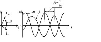
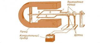
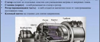
Alternating current, unlike direct current, changes direction and magnitude with a certain periodicity. It is generated by rotating a coil of wire in a magnetic field or, conversely, a magnetic field with a stationary coil.
The induced EMF depends on the sine of the angle through which the generator rotor is rotated. Therefore, all variable electrical quantities are sinusoidal. There are two types of alternating current circuits - single- and three-phase.
AC parameters:
- amplitude: maximum deviation from zero. It is achieved when the coil plane is positioned perpendicular to the field lines. At the moment when the plane of the coil and the lines of force become parallel, the emf drops to zero, then changes sign;
- frequency: the number of complete cycles per second (mainly a current with a frequency of 50 Hz is used);
- instantaneous value: the value of the parameter at a given time;
- effective value (see below).
Disadvantage of alternating current: at low frequencies it is more dangerous for living organisms than direct current.
Single-phase
In a single-phase circuit, the generator has one winding for inducing EMF and one conductor is connected to it. There can be several current sources, but they must operate in the same phase and at the same frequency.
Three-phase
Accordingly, the EMF induced in each winding differs in phase by an angle of 120 degrees (electric angle). When each winding is connected separately, 6 wires are required to transmit energy. The system is called disconnected and today it is not used due to the increased costs of materials.
A connected system is more economically feasible when the windings are connected in one of two ways:
- "star" . The windings on one side are closed at one point. This makes it possible to use one neutral wire, common to all phases, that is, the system turns out to be 4-wire. And if the currents in the phases are equal (symmetrical load), there is no need to use a neutral wire: the currents cancel each other (their vector sum is zero). In this case, a 3-wire system is used;
- "triangle" . The windings form a closed circuit: each end is connected to the beginning of the next. In each phase, a linear voltage is formed that is equal to the phase voltage. But the value of the phase current will be 1.72 times lower than the linear one.
A three-phase power supply system is superior to a single-phase power supply system in the following ways:
- Fewer materials are required for the manufacture of power cables;
- For one installation, two voltages are available: phase (phase - neutral) and linear (phase - phase). That is, when changing the load connection diagram from “star” to “triangle”, two power levels are obtained;
- It is possible to obtain a rotating magnetic field, which reduces the cost of the design of electric motors and other devices. To do this, three windings connected to different phases are placed equidistantly in the motor stator;
- the system is balanced. For example, 3-phase fluorescent lamps almost do not flicker, unlike 1-phase ones. Such a lamp has three lamps or groups of lamps connected to different phases. When the luminosity of one lamp decreases, the neighboring one flares up. Mutual compensation occurs.
Thanks to the balance, the load on the generator is equally distributed and it lasts longer.
Structure
An electrical circuit is a set of devices and elements aimed at delivering current to the consumer and converting it into another type of energy: heat, light or mechanical work.
There are three parts in the circuit:
- power supply;
- transmitting part: wires, switches, transformers, stabilizers, etc. Everything that is used to transmit, transform electrical energy and maintain its quality at the proper level;
- consumers: lamps, electric motors, heaters, etc.
The power source - generator, battery, solar panel - is called the internal part of the circuit, the remaining components are called external. The source is also called an active element, others - passive. The electrical circuit functions only in a closed form, that is, in a continuous form. When opened, the current in it drops to zero, although the section on the generator or battery side remains energized.
Based on the number of pins, circuit components are divided into two types:
- bipolar : have one pair of terminals. Example - diode, resistor;
- multi-terminal : have more than two terminals. Example - transformer (4 pins).
Processes in an electrical circuit are described by Ohm's and Kirchhoff's laws.
The components in it are connected in three ways:
- sequentially;
- parallel;
- in a combined way.
The following terms are used:
- branch _ A section of series-connected elements in a parallel or combined circuit. The laws of electrical engineering state: the current strength within a branch is the same, regardless of the resistance value of its constituent components, and the total resistance of a branch is equal to the sum of the resistances of all its components. In a circuit with only a series connection of components, no branches are distinguished; it is called an unbranched circuit;
- knot . The place where the chain branches. It is generally accepted that the sum of currents converging at a node is equal to the sum of currents emanating from it. The voltage drop for parallel branches between the branching and convergence points is the same;
- outline . A set of branches that represents a closed path for current.
According to functionality, individual parts in the structure of the electrical circuit are divided into the following types:
- power _ Includes elements that generate, conduct, convert and consume electricity;
- auxiliary _ Various additional devices not related to the power section. For example, reactive power compensation installations, fuses;
- measuring _ The devices related to this part allow you to monitor the parameters of the network and devices connected to it;
- manager _ Equipment for adjusting device parameters or turning them on/off.;
- signaling . Reports changes in network parameters by turning on alarm devices.
According to complexity, electrical circuits are divided into:
- simplest: source connected to consumer;
- simple: contain one circuit;
- complex: have several circuits.
In complex chains there are:
- multi-circuit;
- multi-node;
- planar;
- volumetric.
Operating principle of AC network
To understand what a phase is in electricity, you need to understand the features of alternating current. It differs from constant by periodic changes, both in value and direction. Its characteristics are voltage at a given time and frequency (the ratio of the number of cycles to a unit of time). Alternating current is found in outlets and direct connections to the electrical panel.
Single phase current
It is directed from the distribution panel along two wires (phase and neutral), between which there is a 220-volt voltage. In electricity, a phase is a wire that carries electric current to an outlet or appliance. What is zero in electricity? This, in turn, is a cable coming from the outlet through which the current is directed back.
Sometimes the question of what zero is is asked in the context of grounding. Physically these are different wires, although their potentials are the same. Single-phase current can be supplied to the consumer using either two wires (without grounding) or three (with it). Grounding is carried out to drain leaks, protect residents from electric shock and devices from overloads.
Two-phase current
This is a combination of two single-phase ones, offset by 90° relative to each other. Structurally, it looks like a combination of two phase wires (with the indicated shift) and two neutral wires.
Three phase current
Here the design already consists of three current phases, each of the subsequent ones is shifted relative to the previous one by 120 °. In residential buildings, such current is distributed by four wires (three phases and zero) or five (indicated plus grounding). After passing through the distribution board, the sockets in the apartment are fed through one phase and zero.
Electrification of railways using alternating current
The Russian AC passenger electric locomotive EP1P is produced at the Novocherkassk Electric Locomotive Plant.
In Russia and the republics of the former USSR, about half of all railways are electrified using single-phase alternating current with a frequency of 50 Hz. A voltage of ~ 25 kV (usually up to 27.5 kV, taking into account losses) is supplied to the contact wire, the second (return) wire is the rails. Electrification is also carried out according to the 2 × 25 kV system (two twenty-five kilovolts each), when a voltage of ~ 50 kV is applied to a separate supply wire (usually up to 55 kV, taking into account losses), and half the voltage of 50 kV is applied to the contact wire from autotransformers (i.e. 25 kV). Electric locomotives and AC electric trains do not require alteration when operating on 2 × 25 kV sections.
A policy is being pursued to further expand the AC traction range both through newly electrified sections and through the transfer of some lines from direct current to alternating current. Transferred to 1990s - 2000s:
on the East Siberian Railway: section Slyudyanka - Irkutsk - Zima; - on the Oktyabrskaya Railway: section Loukhi - Murmansk; — on the Volga Railway: Saratov and Volgograd railway junctions; - on the North Caucasus Railway: sections Mineralnye Vody - Kislovodsk and Beshtau - Zheleznovodsk.
It should be noted that dual-system electric locomotives are also produced that can operate on both alternating and direct current (see VL61D, VL82 and VL82M, EP10, EP20).
