AC Features
Alternating current has different properties from direct current. They are clearly manifested when an inductance or capacitance is included in the circle.
If you include a coil with a movable iron core in a DC circle, and an incandescent lamp as an indicator, you can see that changing the inductance (introducing an iron core into the coil) does not affect the current strength.
If inductance is present in an alternating current circuit, then with an increase in inductance (gradual introduction of an iron core into the coil), the current decreases. Inductance in an AC circuit creates a certain resistance (but without generating heat), it is called reactance .
If you include a battery of variable capacitors in a DC circuit, then no current will flow at any capacitance (the capacitor breaks the circuit).
If a capacitance is included in an alternating current circuit, then the current exists, and the larger the capacitance is included in the circle, the greater the current. Capacitance in an AC circuit creates a certain reactance that is inversely proportional to the capacitance.
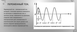
Charged particles that form a constant current move, albeit slowly, but all the time in the same direction with a constant speed. In alternating current, the direction of movement of charged particles changes in accordance with changes in the emf.
Technical alternating current (f = 50 Hz) is called quasi-stationary , since the length of its electromagnetic wave λ\lambda λ = c Т сТ сТ = 6 x 10³ km is very large compared to the length of the circle conductors. In this case, the current strength at any time is almost the same in all sections of the circuit. Kirchhoff's laws can be applied to quasi-stationary current.
The advantages of alternating current over direct current are that it can be easily transformed from one voltage to another, and it is also easier to generate than direct current.
Methods
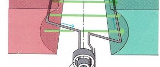
Thus, to obtain alternating current, it is enough to rotate a wire frame with an electrical circuit connected to its ends in the field of a permanent magnet. The source of energy is the force that rotates the frame and overcomes the resistance of the magnetic field.
Every half turn, the conductors of the frame change the direction of movement relative to the poles of the magnet; accordingly, the direction of the EMF in the frame also changes.
Receiving alternating current
The angle between the velocity vector and the field lines varies according to the law α = w*t, where:
- W —angular velocity of frame rotation, rad/s;
- T is the time elapsed from the initial moment when the velocity vector was parallel to the lines of force, s.
That is, the EMF depends on sin (wt): E = f (sin (wt)). Consequently, the graph of changes in the EMF value over time has the form of a sinusoid. The alternating current caused by this EMF is called, accordingly, sinusoidal.
The simplest generator described can be improved:
- The permanent magnet is replaced with an electric one by placing several coils in the stator (excitation winding). As a result, a uniform magnetic field is obtained and thus an ideal sinusoidality of the EMF is achieved (the quality of operation of the devices increases). The excitation winding is powered by a low-power DC generator or battery;
- instead of one frame, several are placed on the rotor: the EMF increases several times. That is, the rotor is also a winding.
The problematic part of such a generator is the moving contact between the rotating rotor and the electrical circuit.
It consists of a copper ring and graphite brushes, pressed against the ring by springs. The higher the power of the generator, the less reliable this unit is: it sparks and wears out quickly. Therefore, in powerful industrial generators installed at power plants, the stator and rotor windings are swapped: the excitation winding is placed on the rotor, and the inducing winding is placed on the stator.
The moving contact remains, but due to the low power of the excitation winding, the requirements for it are reduced. Industrial AC frequency is 50 Hz. That is, the voltage periodically changes direction and magnitude 50 times per second or 3000 times per minute. If there are 2 poles in the excitation winding, to achieve this frequency, the rotor must rotate at a speed of 3000 rpm.
This is what happens in generators of thermal and nuclear power plants. But in hydroelectric power plants, it is physically impossible to rotate the rotor at such a speed: the propellant is falling water, and its speed is much less than the speed of superheated steam with a pressure of 500 atm.
In addition, the rotor of the hydraulic station is enormous in size even at a rotation speed of 3000 rpm.
Its outer sections would move at the speed of a supersonic fighter, which would lead to the destruction of the structure. To reduce the number of revolutions, increase the number of pole pairs in the electromagnet. The rotation frequency will be W = 3000 / n, where n is the number of pole pairs. That is, if there are 10 pairs of poles, to generate alternating current with a frequency of 50 Hz, the rotor must be rotated at a speed of only 300 rpm, and with 20 pairs - 150 rpm.
In electrical engineering, another method of producing alternating current is practiced - by converting direct current. An electronic device is used - an inverter, consisting of power transistors, a microcircuit that controls them and other elements. At the output of the inverter, you can obtain an alternating voltage of any magnitude and frequency. The simplest circuits produce rectangular alternating voltage, while more complex and expensive ones produce stabilized sinusoidal voltage.
Examples of inverter applications:
- switching power supplies and inverter welding machines. The mains current with a frequency of 50 Hz is rectified and then fed to an inverter, which produces an alternating current with a frequency of 60-80 kHz. Purpose: at such a high frequency, the dimensions of the transformer and losses in it are sharply reduced, that is, the device as a whole becomes more compact and economical;
- autonomous diesel and gasoline generators to power equipment sensitive to voltage quality. A diesel generator in its pure form produces low-quality current, since its shaft rotation speed changes when the load is converted. The inverter eliminates all these fluctuations and produces a stable, high-quality voltage at the output;
- DC power lines.
For a number of reasons, it is more profitable to transmit particularly significant powers over very long distances using direct current rather than alternating current. At the final point, it is converted by an inverter into AC power frequency and sent to the local power grid.
Receiving mechanism
It is known that there are two types of alternating current:
- single-phase;
- three-phase.
Single-phase and three-phase AC voltage
It is worth considering the differences in the methods of obtaining these types of current.
Single-phase
In a 1-phase generator, all the coils of the induced winding are connected to one line. Consumers are powered by a 2-wire wire (phase and neutral). The voltage in the 1-phase network is 220 V.
Three-phase
The induced winding of a 3-phase generator consists of 3 parts, located at an equal distance from each other and each connected to its own line. That is, the angle between them is 1200. As a result, in each line the current is shifted in phase relative to the adjacent one by the same angle.
The voltage in each line in the distribution network is the same 220 V, but the phase-to-phase voltage due to the phase shift is already 380 V. In a 3-phase consumer device, for example, a motor, there are also three circuits connected at the 1st point ( “star”) or in 3 (“triangle”).
Such a load is called symmetrical and to connect it a neutral wire is not needed at all: the currents of each phase cancel each other out at common points. But often the load is asymmetrical: in addition to 3-phase consumers, 1-phase consumers are powered by separate phases.
Then the currents in the phases are unequal and mutual cancellation will not happen - at least 1 neutral wire is needed.
The main advantages of 3-phase power supply:
- simplifies the transfer of high power.
- it becomes possible to create a rotating magnetic field in electric motors.
Industrial power plants only have 3-phase generators.
If the neutral wire breaks, 1-phase consumers connected to different phases are supplied with a voltage of 380 V, which leads to their breakdown. Therefore, in Western countries, each phase is equipped with a neutral wire. In our country, because of savings, we still use one common one.
Converter circuits
Inverters are classified according to their operating principle, shape and design.
Operating principle
Based on this feature, devices are divided into two types: autonomous and grid-driven inverters.
Autonomous ones are divided into several subgroups that combine inverters:
- voltage (IN): installed in most UPSs;
- current;
- resonant.
Inverters driven by the network are otherwise called dependent. They are used, for example, as power converters on electric locomotives.
Scheme
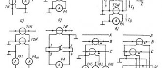
There are several basic inverter schemes:
- bridge IN without transformer a. It is used in UPSs with a power of over 500 VA and in various devices designed for 220 or 380 V;
- IN with zero terminal transformer a. Used in UPS with a power of 250-500 VA, in 12 or 24 V installations and mobile radio transmitters;
- bridge IN with transformer . Used in UPS of critical facilities with power consumption from several kVA to tens.
Schematic diagram of the converter
Form
According to the form of output voltage, inverters are divided into:
- IN with square wave output signal . In order to ensure the required proportionality of Uout. the control circuit varies the relative duration of the pulses with the keys or phase shifts the control signals of antiphase groups of keys (depending on the design features of the switching module);
- IN with stepped output voltage . The input signal is processed in two stages: by high-frequency conversion, a unipolar step signal is formed, close to a sinusoid with a period halved, and with the help of a bridge converter it is converted into a multipolar one with the required period;
- IN with sinusoidal output voltage . The input DC current is also processed in 2 stages: by high-frequency conversion, a DC voltage is generated, almost equal to the amplitude of the required AC voltage, and then by a bridge inverter, operating on the principle of multiple pulse width modulation.
The resulting direct voltage is converted into a nearly sinusoidal alternating voltage.